Project showcase
Mechanical Drawing & Bill of Materials
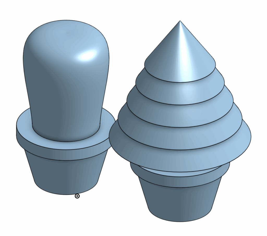
For my Fusion CAD assignment, I designed a pot that could hold various types of houseplants. To showcase my idea, I created a cactus and a small Christmas tree to accommodate the pot. I created this design in OnShape as a model and blueprint for a 3D printed project.
The visible part of the design is the tree, while the attachment stub at the bottom would fit into the pot. Because I am relatively new to CAD, I chose this design to effectively refine three main skills.
Firstly, I chose to design interchangeable plants for the pot as it would test my skills to measure and assess the correct dimensions for each part to ensure it would fit with the pot’s hole and scale. Secondly, I chose to create a round cactus and a layered tree to demonstrate my ability to sketch complicated drawings and to make use of different methods of realizing sketches, such as with revolving and extruding. Lastly, designing these lego-like structures allowed me to practice with assembling detached parts.
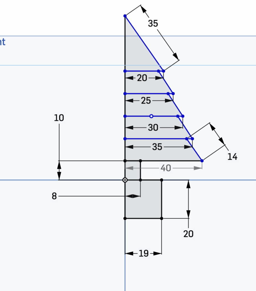
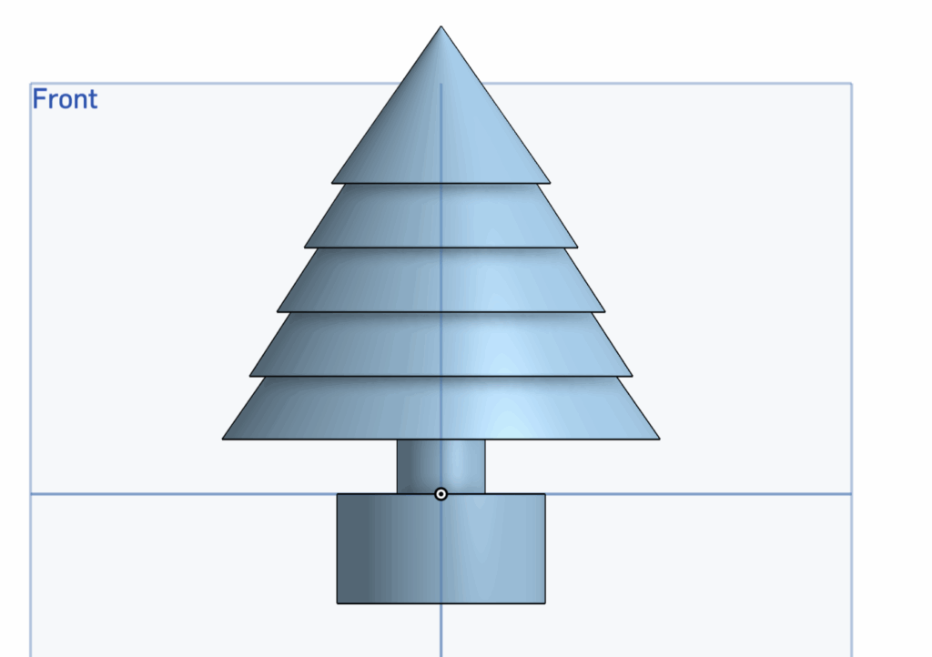
The overall process of creating this project can be divided into 3 main sections. The most important part of this design is the initial sketches. This sketch not only presents the shape of the plants and pot, but also maps out their dimensions to ensure each part connects with one another. The showcased example is a front-view sketch of the Christmas tree. On the bottom of the sketch, I decided to create an attachment block of standard dimensions (19 mm x 20 mm) that would fit into my pot hole. Each of the Christmas tree’s layers decrease by width incrementally, while maintaining a constant height. This helps to create symmetry in my design and ensures that the dimensions of the project would be easy to replicate by others viewing the mechanical drawing.
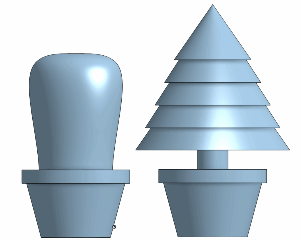
The next step of the project is to realize these sketches. This would be accomplished with two main tools, revolve and extrude. The revolve tool allows a user to select an axis from their sketch and create a 3D model by rotating the 2D sketch around the selected axis, until either it meets itself to create a ring shape or the user stops the revolve to create a shape similar to a slice of pie. This tool is helpful for designing circular models, such as in this case for the body of the cactus.
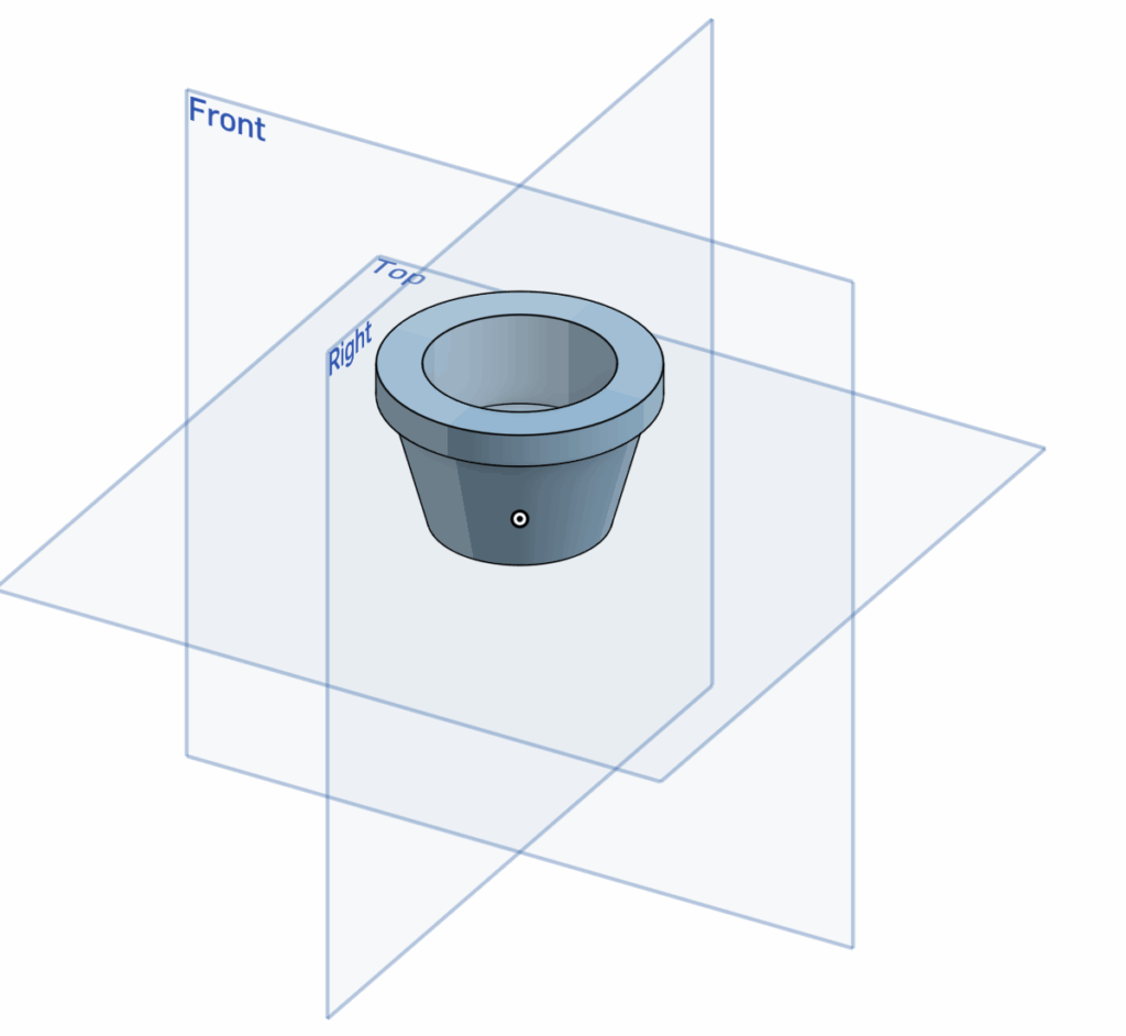
The second tool is to extrude the sketch, which creates a 3D model by extending a selected sketch with material to the front or back. This tool is especially useful for adding layers to a set sketch. This tool was used to create the attachment units connected to each plant. This second step creates 3D models for the sketches that can then be placed in assembly to review how each part interacts with one another. This interaction can be created using mates that connect the parts together, and can be seen in the mechanical drawings, as well as in the image below.
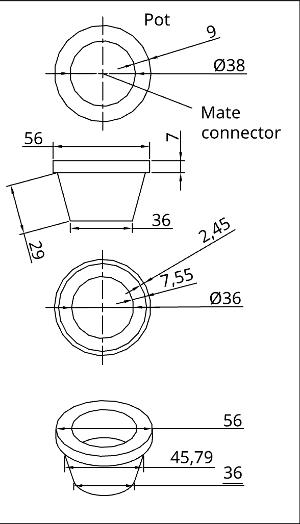
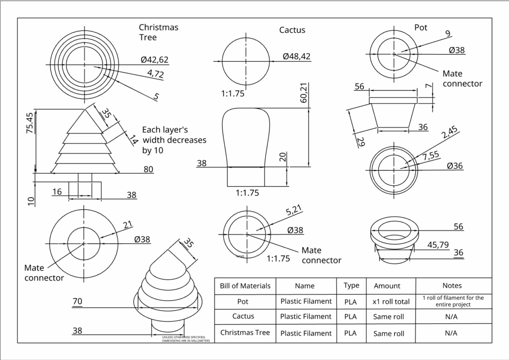
Lastly, a mechanical drawing and bill of materials are included. This drawing essentially builds a blueprint for the project. The purpose of a mechanical drawing is to allow others viewing the project to understand and be able to replicate the design, with the correct dimensions and scale. I decided to include the top, front, bottom, and isometric view for all 3 parts of my project.
The bill of materials serve a similar purpose, allowing a user to understand which materials they would need to replicate my design. Because I created the blueprint for a 3D printed project, my material only includes plastic filament of a specified type (PLA).
Ultimately, by combining my skills in sketching, extruding & revolving, assembly, and creating a mechanical drawing with a bill of materials, I was able to create a simple houseplant CAD design.
AI Usage Transcript
Attached below is a transcript of my AI usage. I did my best to understand each component of the AI’s suggestions and incorporate them into my designs.
Leave a Reply to mcrompton Cancel reply