Recently, I began research on my personal project. To recap the problem I intend to solve, many people struggle to find parking spaces, especially at large events such as festivals, sports competitions, and concerts. This can lead to significant time delay and a loss in revenue for parking garages with open spots that are overlooked. To address this issue, I created the following definition statement:
“The solution must be easily accessible and easily applicable/adaptable in multiple locations. It must generate revenue, either through additional booking fees, ads, or subscriptions. The solutions should be most suitable for major events, where pre-planning can take place. Parking lots must make sufficient money to compensate for empty spots left by reservations, and open spots must be detectable.”
The target audience for this project is adults and parents, in particular, those who actively participate in such large events. Those living in urban areas or near major sports/concert venues will be a prime target.
Potential Solutions
Below are the potential solutions and drawbacks that I initially foresaw.
Create an app with a subscription-based program that allows you to reserve parking spots in advance.
Set up sensors to detect whether a spot has been occupied.
Collaborate with parking lots to share additional revenue generated from reservations to compensate for the money lost from empty parking spots.
Generate app revenue through additional fees for reservations on the app, depending on the time prior to the booking, through ads, or subscriptions.
Market in social media and through parking lots, as this is a fairly common problem that most people living in urban areas or near major sports/concert venues experience.
Drawbacks
Parking lots, especially in populated areas, may lose revenue because parking spots are left empty for reservations.
Ensuring customers arrive and leave on time.
I intend to keep the majority of these solutions. However, I plan to put a greater emphasis on getting in contact and collaborating with parking garages, rather than marketing the product on social media, as I believe I should approach this project to demonstrate my skills and passion, rather than from a purely business standpoint.
Current Progress
The majority of my original research had been on existing competition, as shown below:
Spot Hero:
A leading digital parking lot booking service in North America, helping to book garages, lots, and valets. Founded in 2011, it operates in over 400 cities in Canada and the United States. Spot Hero makes money by taking a 10-35% commission from parking lot operators for managing reservations, with pricing that varies by location, time, and the local economy.
BestParking:
A prominent parking lot booking service in North America that searches and compares the pricing of different lots to locate an optimal garage. BestParking operates near populated cities, airports, and stadiums. Similar to Spot Hero, it makes money by taking a commission fee from lot operators for connecting and overseeing the interaction between the user and seller.
Recently, I have focused on researching and testing potential website creators and domains. I initially intended to use Squarespace for accessible and flexible use, but its short free trial and requirement of a paid plan to continue usage presented a major downside.
Currently, I’m considering the use of AI website creators, in particular Bolt or Claude, as a simple way to set up the foundation of the website. These AIs have a message limit per day, thus I must draft detailed prompts before each use. The main purpose of Bolt.AI is to create a website with basic features, such as a booking page, search page, home page, payment form, etc. It is also possible to integrate simple AI chatbots into the website to aid navigation.
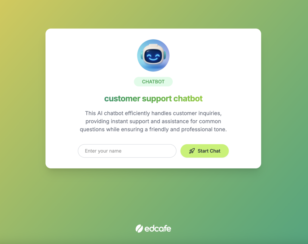
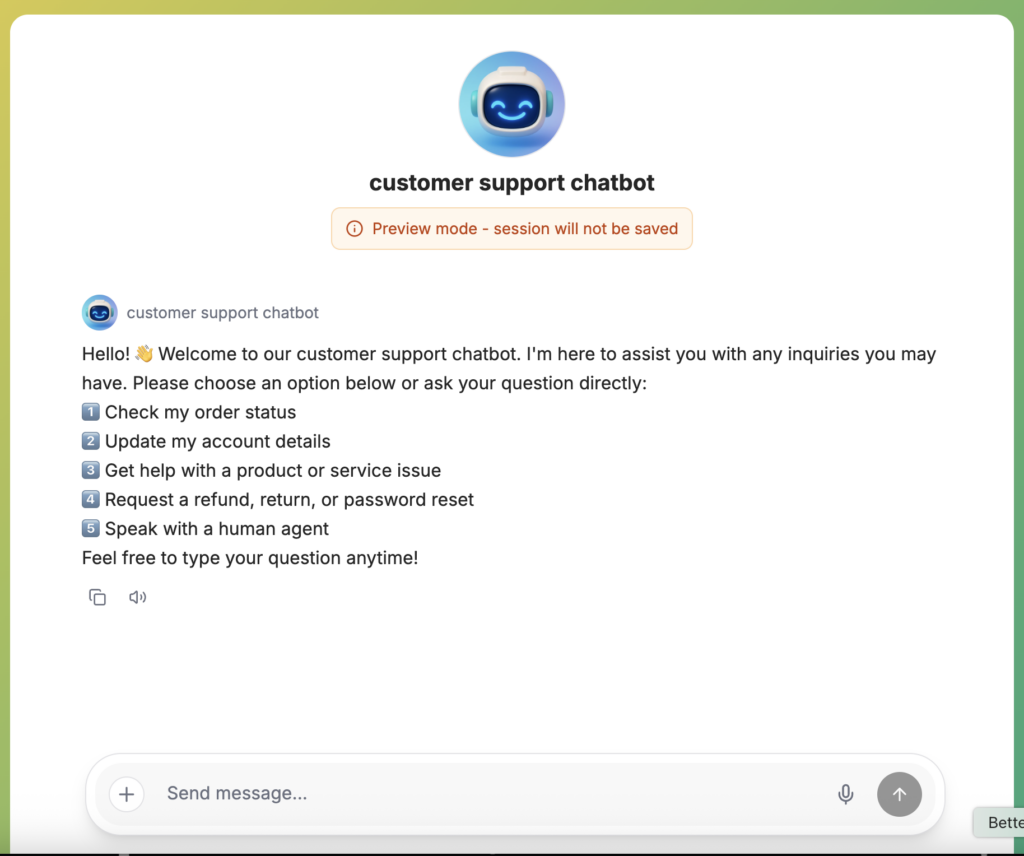
Example of an AI Chatbot made by EdCafe for the purpose of my project.
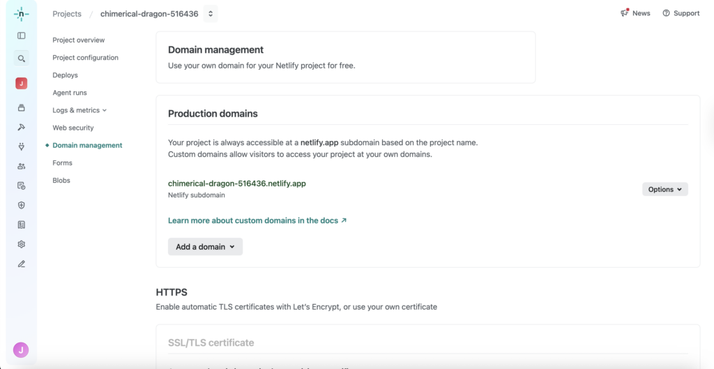
I am also working on the domains provided by Bolt.AI to launch my app on, as shown below:
Through my testing, I discovered that Bolt.AI and other similar AIs excel at creating organized pages of a website, but struggle at including imported images, videos, links, and other external items. I plan to then import the generated code into VS Code or another website creation tool that allows the use of such material.
Documentation
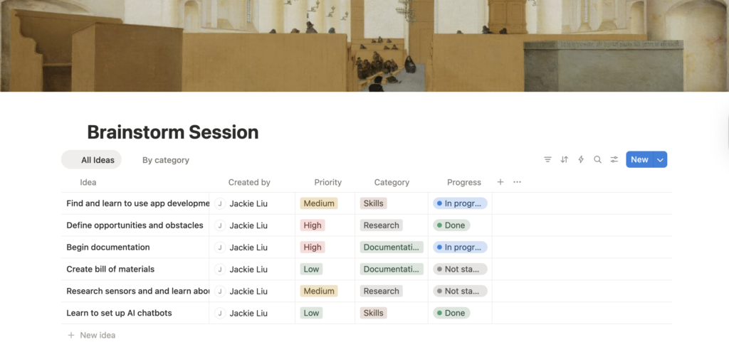
I have also begun documentation for my project, including recording recent progress and planning for the future. This was done on Notion, where I have set up a project overview, timeline, and to-do table
The most significant challenge I am facing at the moment is managing the limited number of messages Bolt and Claude AI provide per day. To accommodate this issue, I must set up a list of pre-written, detailed prompts that I can paste into the AI each day. This process must be started as early as possible to account for any potential delays. I must also learn to export the code and to import the appropriate code language into VS Code.
Next Steps
In addition to addressing the above-mentioned challenges, I plan to focus on researching and testing potential domains to launch my website. More importantly, I must learn to convert my website into an app for better accessibility. The purpose of first creating a website is to be able to test necessary features flexibly, but it may require time to convert the code to fit the requirements of an app.
Many people struggle with finding parking, especially at large events such as festivals, concerts, and sporting events. This, in turn, can result in major delays that postpone plans. Parking lots also lose revenue if they fail to keep track of open spots that customers overlook.
Definition Statement
The solution must be easily accessible and easily applicable/adaptable in multiple locations. It must generate revenue, either in the form of additional expenses for booking, ads, or subscriptions. The solutions should be most suitable for major events, where pre-planning can take place. Parking lots must make sufficient money to compensate for empty spots left by reservations, and open spots must be detectable.
Customer Profile
The target audience for this project is adults and parents, especially those who actively participate in such large events. Those living in urban areas or near major sports/concert venues will be a prime target.
Potential Solutions
Create an app with a subscription-based program that allows you to reserve parking spots in advance.
Set up sensors to detect whether a spot has been occupied.
Collaborate with parking lots to share additional revenue generated from reservations to compensate for the money lost from empty parking spots.
Generate app revenue through additional fees for reservations on the app, depending on the time prior to the booking, through ads, or subscriptions.
Market in social media and through parking lots, as this is a fairly common problem that most people living in urban areas or near major sports/concert venues experience.
Drawbacks
Parking lots, especially in populated areas, may lose revenue because parking spots are left empty for reservations.
Ensuring customers arrive and leave on time.
Additional Considerations
Scalability:
This solution is relatively easy to scale, as long as sufficient benefits (mostly in revenue) are presented to parking lots. Scalability requires more parking lots to be contacted in populated areas and the implementation of sensors to detect occupied, reserved, and open spots.
Existing Competition:
Spot Hero:
A leading digital parking lot booking service in North America, helping to book garages, lots, and valets. Founded in 2011, it operates in over 400 cities in Canada and the United States. Spot Hero makes money by taking a 10-35% commission from parking lot operators for managing reservations, with pricing that varies by location, time, and the local economy.
BestParking:
A prominent parking lot booking service in North America that searches and compares the pricing of different lots to locate an optimal garage. BestParking operates near populated cities, airports, and stadiums. Similar to Spot Hero, it makes money by taking a commission fee from lot operators for connecting and overseeing the interaction between the user and seller.
Prototype Content
The prototype will likely consist of an app to facilitate online reservations and a physical sensor to detect whether a car has been parked or to scan booking tickets. These prototypes will serve as effective examples of my design’s effectiveness. The app can be used to test digital activity, such as traffic, marketing, and ease of use. On the other hand, by detecting occupied spots, the physical sensors can be used to test the overall accuracy of the app’s statement on whether a parking spot is available for use.
This prototype does not mandate significant material requirements, as the app can be made entirely digitally, while the sensors will only be designed to detect occupied parking spots, thus no advanced models will be needed. However, I may need to train a simple AI and database to recognize cars to avoid confusion in the sensors’ data.
Required Skills
To prototype my project, I will need to learn the basics of app design. Rather than coding the project, a more efficient way to create this may be through the use of app-design products, such as Wix and Squarespace, as well as the aid of AI. AI excels at generating a basic layout with appropriate functionalities for my use, while app/website-design services allow me to optimize the app’s user interface. However, I must learn the marketing basics to launch the app, including studying its domain, trafficking, and accessibility.
For the physical sensors, I must learn to connect the data collected from the sensors to the app itself, as well as to set up an effective design that prevents the sensors from becoming easily obscured by fog, rain, etc. Because the AI is only required to identify cars, it may be feasible to train it within the given time, before May 1st. Tools such as Teachable Machine may be used to aid in training, but I must also gain access to a database.
Timeline
Step 1:
Finalize project ideas
Research and practice necessary skills
Research appropriate tools for app creation and sensors
Determine additional requirements such as revenue, scalability, and accessibility
Step 2:
Prototyping the app
Design a simple AI to recognize parking occupancy
Connect sensors to AI, and connect its database to continue training the AI in the future.
Step 3:
Testing AI accuracy
Testing sensor accuracy
Collect user feedback on app design
Step 4:
Refine app and sensor design based on testing data and feedback
This report covers the testing (second) phase of the Fusion Planetary Explorations Project, where we investigate a celestial body suitable for inhabitation and build a solution to do so. This page outlines the testing intentions, the process of designing and building our prototype, the collected data, and an analysis of our test results.
Definition Statement
Our chosen location for the Fusion Planetary Exploration Project was Titan, Saturn’s largest moon. We chose this location due to the many opportunities it brings in natural energy, oxygen, and atmosphere. However, some challenges must be addressed for permanent inhabitation.
When designing a vehicle suitable for Titan, the critical problems we must consider are its ability to accommodate 4 people and its machinery under extreme temperatures of -180°C, hold sufficient energy to travel distances of 10km at a time, be able to produce oxygen, and have sufficient traction to grip Titan’s unique surface of ice, dunes and pebbles alongside combating the lower gravity similar to the moons.
Purpose of Test
The intentions of our test include two main points:
The effectiveness of spiked treads on different terrains, namely, on soft and slippery terrain, to imitate the deserts and ice sheets that cover Titan.
Distance testing, to understand if our prototype’s motors can complete a sufficient distance that, when scaled to the intended size, can drive a continuous 10 km trip.
Based on this data, we aim to find the efficiency of our motors and the energy needed to power them. This will be done with the help of the video analysis lab. We intend to adjust our design based on this data, mainly by taking into consideration how scaling our prototype may affect performance. For example, how the real design’s weight affects the tread’s effectiveness on sand.
Test Apparatus
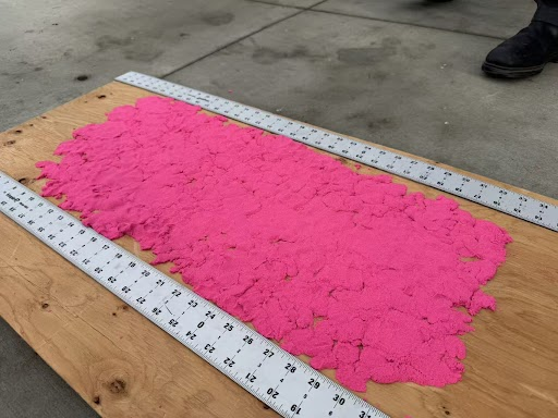
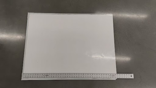
The tests for our prototype intend to imitate the vast deserts and ice sheets that cover Titan. Our desert environment will likely be a large pillow or soft mattress, as they are easily compressed under heavy weight. If accessible, an area of real sand, large enough to imitate dunes, will be used for the most accurate results. The shifting surface caused by this compression test tests how our vehicle’s treads and spikes perform to keep the vehicle stable. The icesheets can be mimicked using a clean whiteboard, or if unrestrained by budget, with ball bearings. This environment tests our tires’ traction and their ability to traverse slippery surfaces. Our final testing apparatus is shown below.
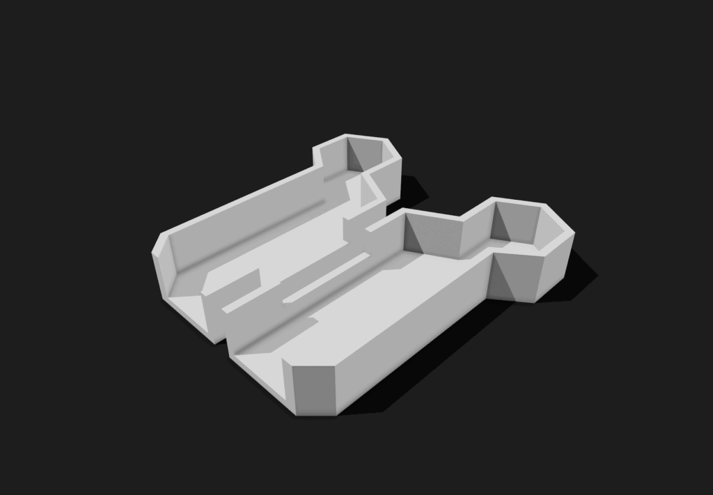
Prototype Design – Vehicle Body
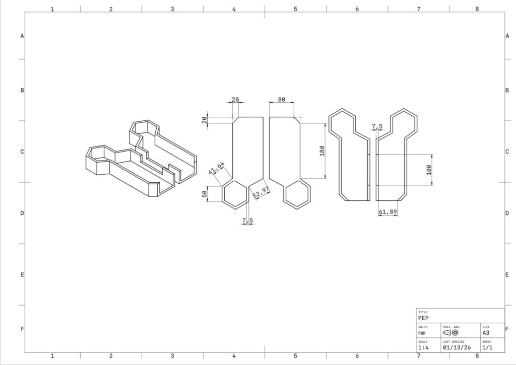
The CAD designs below showcase the initial design of our vehicle’s main body. We originally decided on a rectangular body, where all the mechanical components, such as motors, batteries, Arduino board, etc., would be stored. A hexagonal head is attached to this body as the main control center for the vehicle.
The primary issue we encountered with the initial design of the vehicle body was that it was too large and complex for efficient testing. The roof of the vehicle covered the mechanical components, making it difficult to adjust our Arduino, while the head of the design served no purpose in the prototype itself. Based on these issues, we redesigned our vehicle body to be lighter and simpler, boasting only a rectangular frame with an exposed roof for easy access to adjusting our Arduino. The simpler design also allowed us to reprint the body if necessary.
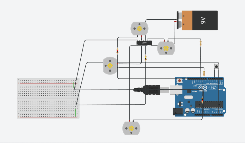
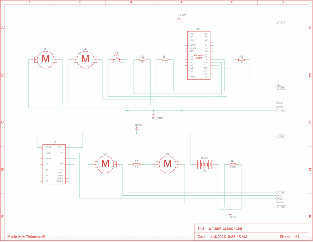
Prototype Design – Arduino System
The designs below showcase the initial design of our vehicle’s Arduino system. A motor driver acts as the motherboard of the system. This motor drive is connected, through the breadboard, to the power pin on the Arduino board. Four motors are attached to the motor driver to power the 8 wheels that make up our original treads. Lastly, a button is wired into the system such that when pressed, the four motors run simultaneously, as this allows for easy control in the testing environment.
The full Arduino code for this system is attached below.
int buttonPin = 2;
int motor1 = 9;
int motor2 = 10;
int motor3 = 11;
int motor4 = 12;
// assigning the motors and buttons to pins on the Arduino Board

bool motorState = false;
bool lastButtonState = HIGH;
// setting up variables to detect button and motor state

void setup() {
  pinMode(buttonPin, INPUT_PULLUP);
  pinMode(motor1, OUTPUT);
  pinMode(motor2, OUTPUT);
  pinMode(motor3, OUTPUT);
  pinMode(motor4, OUTPUT);
}
// connecting the input and output of motors to button clicks

void loop() {
  int reading = digitalRead(buttonPin);
  // detect a button press through its state (high/low)

  if (reading == HIGH && lastButtonState == LOW) {
    motorState = !motorState;
    delay(50);
  }
  // set the motor state to true if button press is detected

  lastButtonState = reading;

  // power the motors if the motor state is true
  digitalWrite(motor1, motorState ? LOW : HIGH);
  digitalWrite(motor2, motorState ? LOW : HIGH);
  digitalWrite(motor3, motorState ? LOW : HIGH);
  digitalWrite(motor4, motorState ? LOW : HIGH);
}
Our Arduino system faced difficulties in obtaining sufficient battery power to run effectively. The digital design on Tinkercad differs slightly from the physical design, mainly in the battery voltage and the number of connections that could be made to a single pin. From this issue, we decided to simplify the Arduino design to be a minimum viable product (MVP), as the system itself is not the primary focus of our tests.
Initial Testing
The main issue our initial test encountered was securing the treads onto our wheels. Our original design was set up to use 3D-print filament to print our wheels, tape around the wheels to provide traction, and rubber treads. However, when assembling our prototype, we failed to consider how hot glue melts through such soft material. Due to this issue, we decided to edit the prototype to replace the treads with wheels. This was done in order to test the second intention of this experiment, which was to determine whether the motors provided sufficient energy to power the vehicle. The motors themselves worked to our expectations; however, a stronger material for the axle that replaces the original wooden ones may aid in transferring more of the motors’ power into the wheels themselves and provide more efficiency.
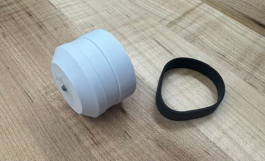
Final Design
To address the issue we faced in the first prototype, where the rubber treads were too loose to attach and easily melted under hot glue, we redesigned the wheels to include an indentation for secure attachment. We decided to exchange the large treads for smaller, more elastic ones that would be fitted across each wheel instead of over four. This design allows for firmness without additional hot glue. We also replaced the original wooden axles with metal ones to prevent bending under the tighter treads.
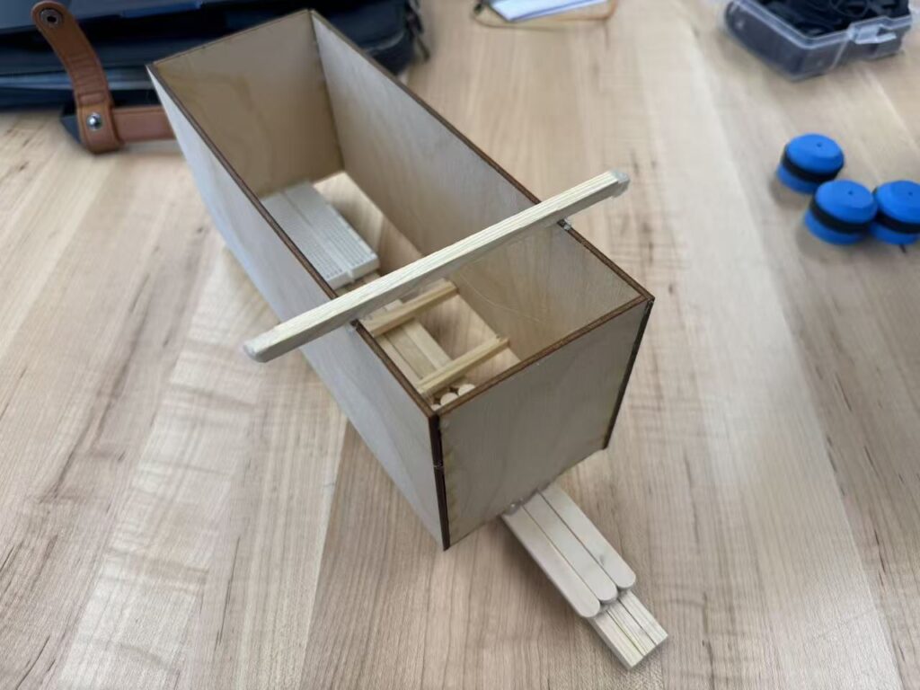
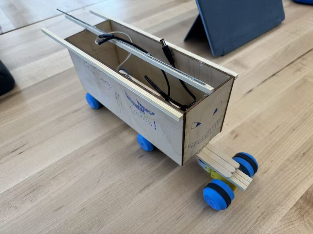
Our final design replaces the first prototype’s bulky vehicle body with a simpler model. We decided to remove the vehicle’s head, as it did not serve a purpose in our tests. The roof is exposed to allow easy editing with the Arduino and motors, and the laser-cut material provides for a lighter weight. A counterweight is also attached to the top of the vehicle to prevent toppling under the lighter load.
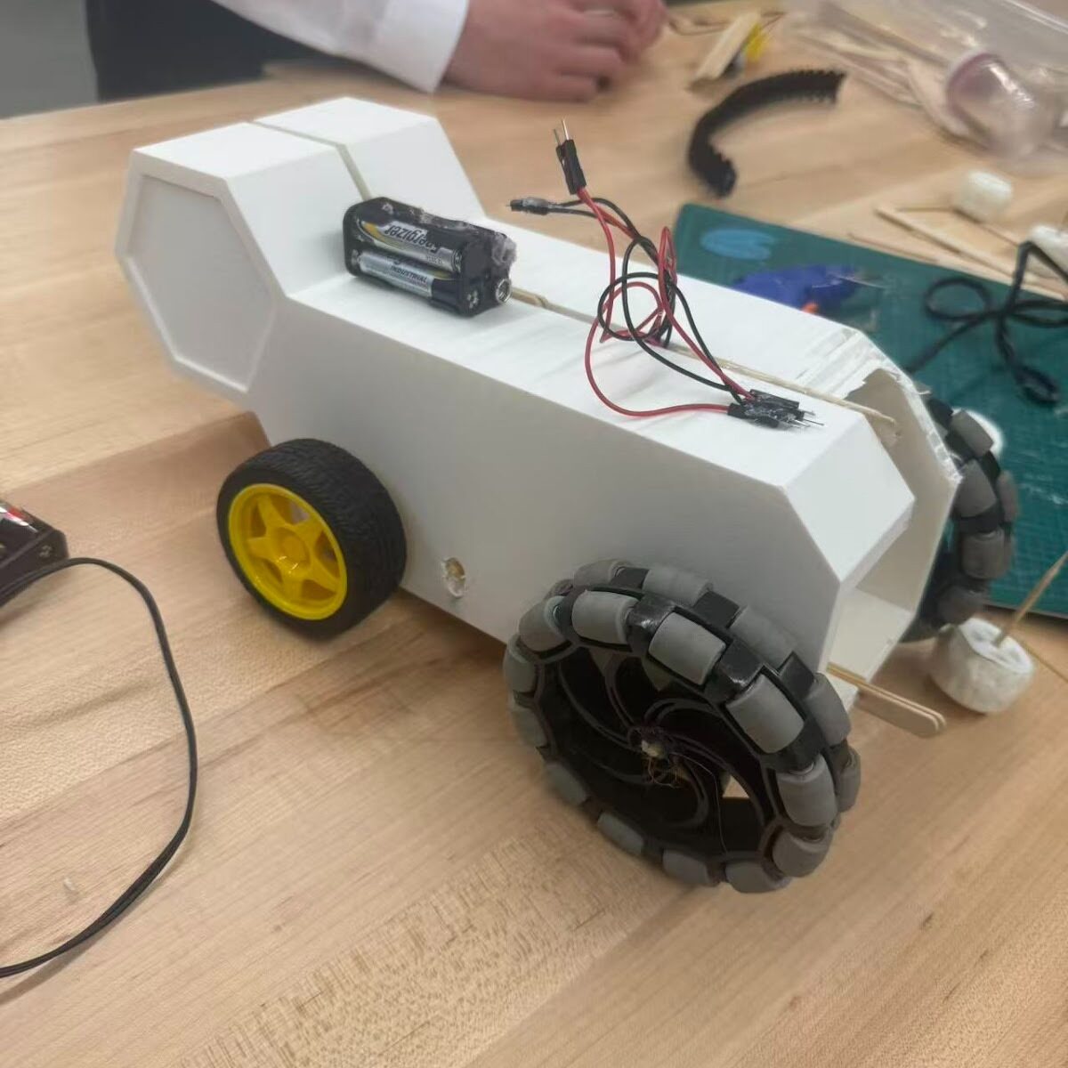
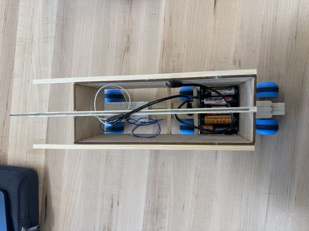
Our finished product combines the newly designed wheels and vehicle body with a new counterweight. The Arduino system is accessible inside the body, and the motors are attached below. The vehicle runs by connecting the two power cords, and is stabilized by the beams that extrude backwards. Our main considerations for the final design intend to keep the vehicle light and easily balanced, and for the wheels to be accessible on different terrains.
Additional photos of final prototype
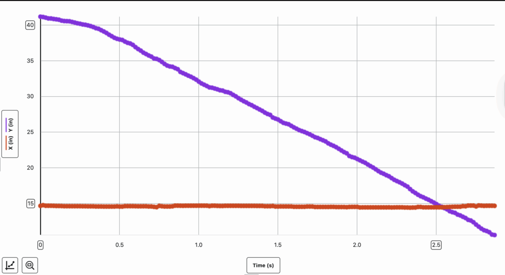
Testing Day
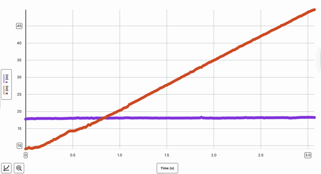
The results of our second testing day have been attached below. The test followed our hypothesis, and the treads performed effectively against the different terrains. Due to its performance, we decided to run a test on a grassy terrain, where it was more rocky and uneven than the sand. This test acts as an indicator of how well the vehicle may run over large dunes, rock formations, and rugged surfaces. The test results were an overall success. Our vehicle faced minor instabilities while travelling over the terrain, but this issue was mitigated through the implementation of counterweights.
Additional Testing on Grassy Terrain
Data Collection
The goal of data collection is to find the efficiency of the vehicle. Using an ammeter and voltmeter, we found that the current and voltage of the vehicle were 0.52 Amps and 7.34 Volts, respectively. This data will act as the input for the vehicle’s efficiency, as it measures the energy the motors receive from the batteries. The mass of the vehicle was measured to be 506.7 g. Through the Vernier Video Analysis Lab, we were able to calculate the speed of our vehicle, finding it to be 0.28 m/s on sandy terrain and 0.34 m/s on icy terrain. This data will act as the output for efficiency.
The main goal of our data analysis is to determine the efficiency of our vehicle, following the formula below:
Efficiency is expressed as a percentage. The input energy of our vehicle refers to the amount of energy, in Joules, applied to our system. By multiplying 0.52 Amps by 7.34 Volts, can find the power input into our vehicle to be approximately 3.82 Watts. Power can be converted to energy by multiplying its value by time in seconds. This equation results in approximately 22.92 Joules of energy being input into our vehicle. On the other hand, output energy is the total energy emitted by our vehicle. For our testing, no potential energy and minimal thermal energy in the form of friction are found. Thus, we can determine that the vehicle’s output energy is equal to its kinetic energy. The following formula can be used to calculate the vehicle’s total kinetic energy:
The “m” stands for mass in kg, which in our case is 0.5067 kg. “v” stands for velocity in meters per second. Because we conducted testing on two different terrains, we must find the average velocity of our vehicle across both experiments. This can be calculated by dividing the sum of the two velocities by the number of velocities recorded. The formula is shown below:
Through this formula, we find that the average velocity of our vehicle is approximately 0.31 m/s. Plugging these values of mass and velocity back into our formula for kinetic energy, we find that:
The output energy of our vehicle was found to be approximately 0.0243 Joules. Putting this value into our original formula for efficiency results in the equation:
Based on this equation, we can determine that our vehicle’s efficiency is approximately 0.106%.
Evaluation
Although this efficiency is quite low, it is reasonable considering the small scale of our project. During testing, the uneven terrain caused imbalance within our wheels, which affected their overall speed. Due to this, suspension presents itself as a suitable area of improvement when scaling the vehicle. Enhanced suspension allows our vehicle to better maintain stability, ensuring that energy is not lost without purpose, such as when the wheels cannot make contact with the floor while the vehicle is driving.
Additionally, it is important to consider reducing the weight of the vehicle where possible and adjusting the power and number of energy sources on our vehicle to increase efficiency. Because of the increase in size and weight of a realistic model, friction will likely play a more significant role in our vehicle’s efficiency, whereas it could be disregarded in our smaller prototype. The increase in weight will also be affected by Titan’s lower gravity.
The fuel efficiency of our vehicle was calculated to be ≈0.106%, and the total distance that needs to be covered is 10 km. Reformulating this formula to divide distance travelled by fuel efficiency gives the total fuel used, which is calculated to be:
≈94.14 litres of fuel are required for the vehicle to travel the full 10 km. To better preserve energy, when scaling the vehicle, axles on the wheels should be secured more tightly to avoid rotating without moving the wheels. The motors and energy source should be maintained as similar to a closed-system as possible, to avoid losing kinetic energy when functioning. This may be done through trapping the heat produced from the energy system using materials with low thermal conductivity, by making use of a regenerative system that recycles energy that would originally be wasted, etc.
Conclusion
Our prototype design and testing were an overall success. We were able to determine that our vehicle performed differently across varying terrains, as shown by changes in velocity, but maintained relative stability across both environments. The initial testing allowed us to redesign our vehicle to boast a lighter, more accessible body and a simpler Arduino system, allocating more time and focus to the main purpose of testing. We determined the vehicle’s effectiveness on sandy and icy surfaces, reflecting that of Titan’s terrain. Moving into the future, we aim to conduct a greater quantity of minor testing for our projects, rather than large-scale ones that may be hard to adjust. When scaling the vehicle, the greatest challenge we face is in optimizing the low energy efficiency.
AI Usage
The full AI-usage transcript for this project is attached below
The Fusion Planetary Exploration Project challenges us to investigate a potential celestial body suitable for inhabitation. The choice that stood out most to us was a famous one of Saturn’s 274 moons, Titan.
One of our primary reasons for choosing Titan is its proximity to the Earth relative to other Earth-like planets/moons. Being 1.2 billion kilometres, and about 6-7 years of continuous space travel away from us, as compared to the thousands of light-years of others, there is a real possibility of human reach extending out to this moon.
Opportunities
Aside from its proximity, Titan’s surface is made primarily of ice, which covers a rocky surface that allows space vehicles to land on. We can find important opportunities in these lands, as well as take inspiration from many of the ISS’s methods of sustaining life. Firstly, we can obtain a sustainable water source through recycling urine. As NASA’s recent report on “Environmental Control & Life Support Systems” suggests, this process is achieved through firstly separating the nutrients found in urine from the waste liquid, before distilling this liquid to capture the remaining, drinkable water that is then stored in a urine brine. Alongside consumable water, this procedure allows us to recover key nutrients such as phosphorus and nitrogen to be used in fertilizer, which helps us create farms on Titan. This process may be supplemented, especially in emergencies, by melting Titan’s vast icy surface for water.
Due to Titan’s lack of oxygen in its atmosphere, we must make use of the ISS’s invention of electrolysis. As stated by NASA’s recent report, this process uses large plots of solar panels to capture the energy required to decompose water (H2O) into Hydrogen (H) and Oxygen (O) for us to breathe. The supply of water may be found not only in the urine recycling process, but also be kick-started by melting Titan’s unique, icy surface. We can make use of its extensive sheets of ice to obtain the initial water needed to begin water recycling and electrolysis (oxygen creation), rather than mandating the water to be transported from Earth.
Alongside this, Titan has a thick atmosphere made up of methane and nitrogen, which works to provide the moon with a strong greenhouse effect that protects it from radiation. The hundreds of lakes of hydrocarbon composites, as well as rain formed from hydrocarbon clouds, can be used as a sustainable fuel for machinery, and imply the possibility of long-term human habitation. Hydrocarbons are known as highly-effective fuel sources due to their energy density, safety of use, and ease of storage and transportation. Titan’s complex terrains mandate the efficient collection and transportation of Titan’s abundance of raw materials, which Hydrocarbon properties are suitable for.
Because of Titan’s many properties that allow it the ability to support, accommodate, and potentially sustain human life, we believe it to be the most suitable candidate for human inhabitation.
Challenges
Despite these promising opportunities, we must not overlook the significant challenges that oppose human inhabitation on Titan. Currently, the two greatest challenges we face include the extreme cold of the atmosphere and the limitations for mass human population. Firstly, due to its remoteness from the sun, being outside the habitable zone, Titan lacks the necessary heat to allow for unmoderated human activity. The conditions of Titan, often reaching -180°C, prompt us to limit our activities to indoors. Our movement may be significantly limited on Titan due to the requirement of heavy clothing and accessories, which may limit our ability to develop appropriate infrastructures and life-sustaining systems on Titan.
Secondly, and perhaps more importantly, there are expected limitations for a large human population. The proposed solutions to creating sustainable water and oxygen sources and to creating fertilizers for farms assume their use for small communities. Processes such as electrolysis require large plots of solar panels, which, when combined with the delicate structures used in urine recycling and the requirement for humans to live indoors, limit the possibility of great infrastructural developments over a short period of time. The ISS’s size reflects this limited growth. Although we are free to use far larger lands on Titan, its distance from Earth restricts the efficient shipping of essential materials to build structures that can host larger human populations.
Lastly, Titan’s distance away from Earth, mandating 14-16 years for a round-trip, means that the inhabitants of Titan cannot make emergency contact with Earth. Emergency aid will not reach Titan in time to be serviceable, and difficult situations, such as system failure in urine recycling or electrolysis, that require immediate attention cannot be addressed.
Vehicle Implications
Appropriate vehicle design would need to accommodate the extreme cold temperatures of Titan. Inhabiters will likely be limited to indoor activities or select outdoor ones with spacesuits. Before official habitation, we must set up large plots of solar panels, indoor-suited infrastructures, drills that allow us to dig into Titan’s underground ocean, and functioning life-sustaining systems that work against the temperature.
Because of Titan’s lower gravity, at around 1.352 m/s² compared to Earth’s 9.807 m/s², vehicle designs require a way to keep it tight to the ground. This issue should be easily approached, as adding spikes on vehicle treads will allow it to grip Titan’s icy surface, similar to the use of studded tires on a snow bike. An appropriate vehicle for Titan must also be able to withstand the moon’s extreme temperatures and allow for remote control of the vehicle without signals. Due to Titan’s thick atmosphere, blockading radio waves and other forms of electromagnetic radiation, we may need to find a workaround for remote control. Pre-programmed and tested directions can serve as an alternative to remote control, albeit with differing probabilities for success as compared to remote control, based on the situation and use case.
How can we be certain of this information?
Our primary source of knowledge about Titan was found through the “Cassini-Huygens” mission. This mission consisted of two important elements. The “Cassini” was a spacecraft designed to orbit and collect data about Saturn. Attached to it, the “Huygens” was a probe designed to land on its largest moon, Titan. As stated by NASA’s Cassini mission report, the spacecraft and probe’s numerous gravity measurements of Titan revealed the liquid water and ammonia ocean beneath its surface, as well as data for multiple lakes and other bodies of liquid methane and ethane, replenished by rain from hydrocarbon clouds.
The Huygen Probe recorded videos, snapping images, and collecting data on Titan’s atmosphere, including its temperature, pressure, density, and chemical composition (nitrogen-rich) during its 2-hour descent. Upon landing, the probe traversed Titan’s surface for over an hour before running out of battery. Delving into a deeper understanding of the spacecraft and probe’s data collection methods, the Huygen carried many technologies that continuously transmitted information from the probe to the mother “Cassini”.
Firstly, the Huygens Atmospheric Structure Instrument (HASI) used a suite of physical, electrical, and thermal sensors to determine the atmospheric properties of Titan. Accelerometers were used to measure the speed of descent of the probe, which, when combined with the information of its weight and the resistance the probe faced, allowed scientists to understand the density of the atmosphere. This, combined with the Chromatograph Mass Spectrometer (GCMS), which was equipped with samplers that tested for the atmosphere’s chemical composition, provided evidence for a Nitrogen-rich atmosphere.
Secondly, the Descent Imager/Spectral Radiometer (DISR) used a range of imaging observations using several sensors and perspectives to create vivid images of Titan. Notably, two imagers, a visible and an infrared, took 360-degree photos of the Huygen Probe’s surroundings during its 2-hour descent. Combined with a side-view imager and a small lamp that adapted its brightness based on the presence of sunlight, provided us with a relatively accurate image of Titan’s physical appearance.
Lastly, the Surface-Science Package (SSP) was a package that contained multiple sensors designed to collect information about Titan’s surface upon the Huygen Probe’s landing. Notably, an acoustic sensor measured the volatility of the probe’s distance to the ground as it landed the last 100 meters (Volatility would remain low against a solid surface, but fluctuate against ocean waves). The above-mentioned accelerometer measured the probe’s deceleration, which suggested the structure and softness of the surface, while a tilt sensor measured any swinging motion during the Probe’s descent (potentially caused by strong winds).
This collected information was continuously transmitted from the probe to the mother “Cassini”. Despite the short duration of the landing, the “Cassini-Huygens” mission provided scientists with a renewed and sophisticated understanding of Titan’s properties. The mission was considered an overall success, revealing a rich atmosphere, an icy surface, the likelihood of an underground ocean, and, most importantly, sparking the interest of scientists in its resemblance to a very young Earth.
Bibliography (APA)
Barnett, A. (Ed.). (2024, November 3). Cassini. NASA. https://science.nasa.gov/mission/cassini/spacecraft/huygens-probe/
Barnett, A. (Ed.). (2024, November 5). Cassini at Titan. NASA. https://science.nasa.gov/mission/cassini/science/titan/
Barnett, A. (Ed.). (2025, April 25). Titan Facts. NASA. https://science.nasa.gov/saturn/moons/titan/facts/
Brown, M. J. I. (2022, December 7). Why doesn’t the International Space Station run out of air? Australia Broadcasting Corporation. https://www.abc.net.au/education/why-the-international-space-station-does-not-run-out-of-air/13928762
Madani, D. (2023, June 28). Astronauts’ urine and sweat are almost entirely recycled into drinking water with new system. NBC News. https://www.nbcnews.com/science/space/astronauts-urine-sweat-almost-entirely-recycled-drinking-water-new-sys-rcna91619
Ridgeway, B. (Ed.). (2025, April 4). Environmental Control and Life Support System (ECLSS). NASA. https://www.nasa.gov/reference/environmental-control-and-life-support-systems-eclss/
US Energy Information Administration. (2023, December 26). Hydrocarbon gas liquids explained. US Energy Information Administration. https://www.eia.gov/energyexplained/hydrocarbon-gas-liquids/
#include <Servo.h>

int red = 9;
int yellow = 8;
int green = 7;

Servo signServo;

int servoPin = 13;

void setup(){

  pinMode(red, OUTPUT);
  pinMode(yellow, OUTPUT);
  pinMode(green,  OUTPUT);

  signServo.attach(servoPin);
  signServo.write(0);

}
void loop(){
digitalWrite(red, HIGH);
 delay(3000);
digitalWrite(red,  LOW);
signServo.write(180);

  digitalWrite(yellow, HIGH);
delay(1000);
  digitalWrite(yellow,  LOW);
delay(500);

digitalWrite(green, HIGH);
delay(2000);
digitalWrite(green,  LOW);
signServo.write(0);

digitalWrite(yellow, HIGH);
delay(1000);
  digitalWrite(yellow,  LOW);
delay(500);

}
For my robotics assignment, I decided to create a simple traffic light mechanism. I chose to keep this project simple due to my limited prior experience in robotics, and specifically Arduino. To provide an overview, this mechanism utilizes three LED lights to represent the red, yellow, and green lights in a traffic light. The LEDs are controlled by a timer, which triggers the swap of the active LED at the appropriate time. A mechanism rotates to change the sign from “Go” to “Stop” whenever the active LED changes.
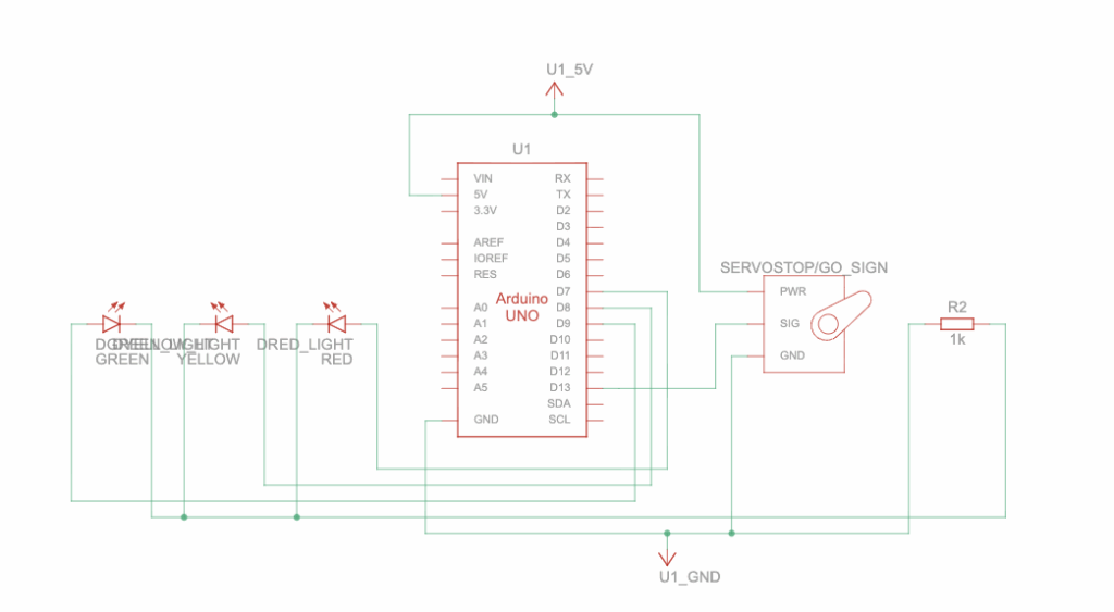
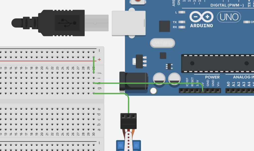
This circuit schematic demonstrates how the Arduino circuit actually functions. To start, the Arduino UNO acts as the brain of the circuit, and controls which LED is turned on at which time and when the servo motor moves. Specifically, the Arduino UNO is the power source of the circuit, providing power to the lights and motor and storing the uploaded code. Next, the LEDs are split into 3 colours: green, yellow, and red. Each of these LEDs have two pins that conduct power from pins D7, D8, and D9 on the Arduino. The LEDs are connected to a resistor, marked by R2 on the right, with a resistance of 1k Ohms to limit the current flowing from the Arduino pins and prevent overloading the circuit.
Following this, the Servo Motor (Stop & Go Sign) has three ports, each with a unique purpose, that receive power from the Arduino to rotate a small motor, which swaps the signs. As indicated by the wires, the power port connects to the 5 Volts output on the Arduino, which gives the servo the electricity needed to function. The GND port connects to the Ground, which completes the circuit so the current can flow properly. Lastly, the SIG port connects to the signal, which allows the Arduino to send instructions from the code to the servo, allowing it to rotate at the appropriate time.
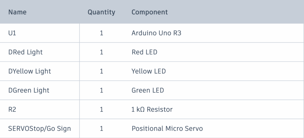
Attached above is the Bill of Materials for my traffic light project. The Arduino UNO R3 is the model of the actual Arduino circuit board. The LEDs, combined with the resistor, act as the traffic lights. The Positional Micro Servo indicates a motor that rotates based on given positions, rather than in continuous motion. Aside from this, female-male and male-male wires, as well as a breadboard, are needed to create the design.
#include <Servo.h>
// import the servo motor library

int red = 9;
int yellow = 8;
int green = 7;
// define which pins on the Arduino each LED is connected to.
// set the variable values to "Integers" to accommodate the Arduino pins.

// lines 1-8
The code for this project is relatively simple due to the repeated use of similar commands. To start, the #include <Servo.h> imports a special library into the code that allows the Arduino to control the servo motors with many pre-set functions with parameters. Next, 3 variables are defined for the 3 LED traffic lights. The values of the variables determine which pins on the Arduino the LEDs are connected to.”int” restricts the variables’ defined values to integers to accommodate the integer numbers on the pins on the Arduino board.
Servo signServo;
// Connects the servo motor to the Arduino board and allow the Arduino to send commands to the motor.

int servoPin = 13;
// Define the Arduino pin the servo motor is connected to.

// Lines 10-14
Following this, a servo object is created using the imported “Servo.h” library. “Servo” prepares a servo object to be used from this library, while the “signServo” function gives this object a name. Because the servo motor is physically connected to the Arduino board, this function acts like a remote control that allows the Arduino to send commands to the servo. Similar to the LEDs, the “int servoPin” defines which Arduino pin the servo will draw power from.
void setup(){
// Prepare the LEDs and servo motor for use.

  pinMode(red, OUTPUT);
  pinMode(yellow, OUTPUT);
  pinMode(green,  OUTPUT);
// Tells the Arduino that the LEDs will output power

  signServo.attach(servoPin);
// Connects the previously defined servo to the defined pin (13).
  signServo.write(0);
// Set the servo to its original position.

}

// Lines 16-29
Moving on to the setup function, the main purpose of this portion of the code is to prepare the LEDs and the servo for use, which will be defined in the next few lines. Firstly, the “void” command tells the Arduino code that the following function will not return a result, as it will instead direct power to the LED pins. The “pinMode(colour, OUTPUT)” tells the Arduino that the LED pins are sending power out. The “signServo.attach(servoPin);” connects the previously prepared servo to the “servoPin”, which was defined as pin 13 on the physical Arduino. Finally, the “signServo.write” function sets the position of the servo motor to 0 degrees (starting position).
void loop(){
// Creates a forever loop
digitalWrite(red, HIGH);
// Determines whether when an LED needs to be active, and setting its power to high to turn it on.
 delay(5000);
// Causes the above LED to stay on for 5 seconds before changing.
digitalWrite(red, LOW);
// Turns the active LED off.
signServo.write(180);
// Turns the servo 180 degrees, flipping it from its starting position to display a new sign.

}

// Lines 31-40
To end, the loop function, without any parameters, keeps the rotation between the green, yellow, and red lights running forever. The “digitalWrite” function sets the power of the LEDs. In the showcased example, the red LED starts at a high power, turning it on. The “delay” function, counted in milliseconds, ensures that this function runs for 5 seconds before switching the red LED’s power to low, turning it off. Following this, the servo’s position is updated to 180 degrees, effectively flipping it from its starting position to display a new sign. This code is repeated for each of the 3 LEDs, and restarts at the end due to the forever loop.
Showcasing the physical model, a key difference in circuitry I noticed between it and the virtual prototype was that multiple wires could be connected to a single port on the virtual version. For instance, the power for the LEDs and the Servo Motors could be directly attached to the 5V output on the Arduino Board, whereas on the physical model, I had to find a workaround by connecting the 5V pin to a single line on the breadboard, before attaching the LED and servo wires to that line.
Despite this, I found that the process of making my physical prototype was an overall success, as it was easier than expected to connect each wire to the correct port, to upload the code to the Arduino, to find the correct parts, etc. In the end, I decided against attaching a Stop/Go sign to my servo motor so as to not damage the motor, but I am content understanding that the design functions properly.
AI Transcript
Below is a transcript of my AI usage. Because of my limited prior experience using Arduino in robotics, my main purpose for the use of AI was to learn the foundations of Arduino components and their specific coding language. I found that ChatGPT was the most suitable tool for this as it is able to explain complicated functions in simple terms, as well as with the help of useful analogies.
Project showcaseMechanical Drawing & Bill of Materials
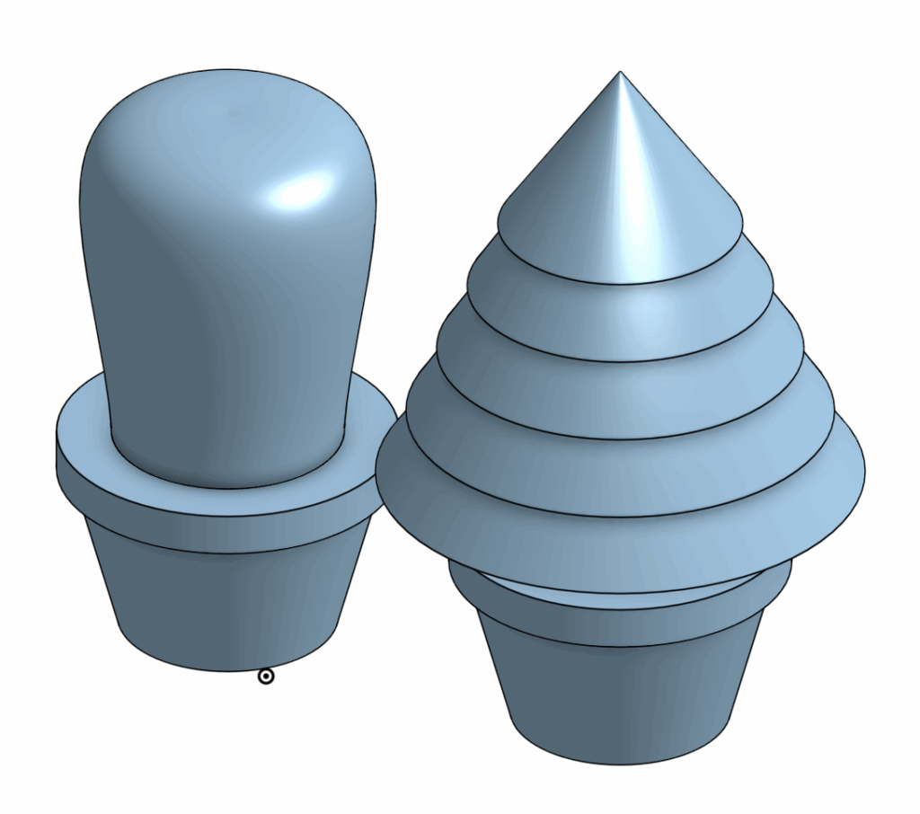
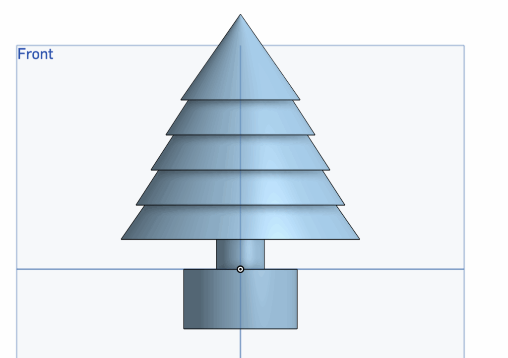
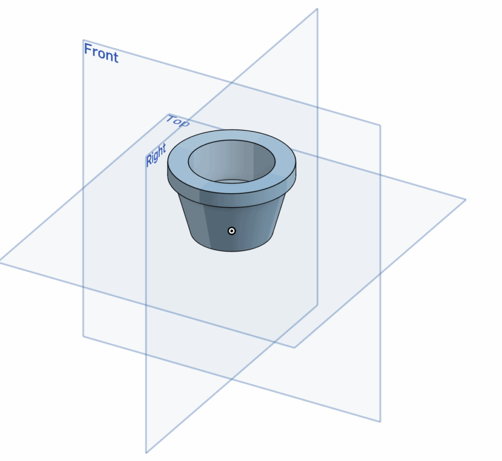
For my Fusion CAD assignment, I designed a pot that could hold various types of houseplants. To showcase my idea, I created a cactus and a small Christmas tree to accommodate the pot. I created this design in OnShape as a model and blueprint for a 3D printed project.
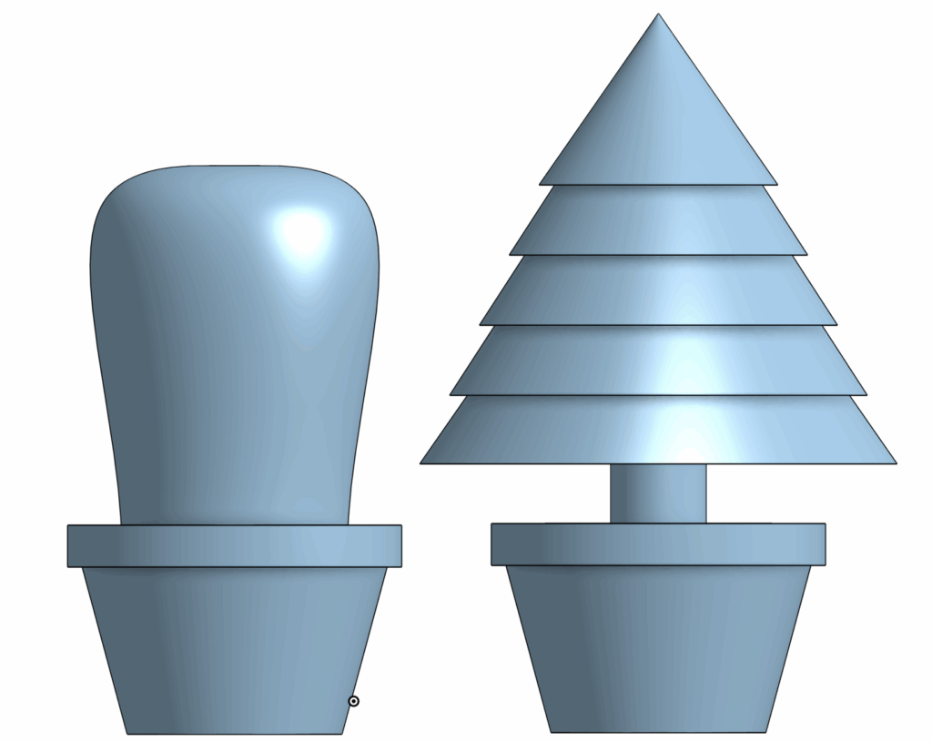
The visible part of the design is the tree, while the attachment stub at the bottom would fit into the pot. Because I am relatively new to CAD, I chose this design to effectively refine three main skills.
Firstly, I chose to design interchangeable plants for the pot as it would test my skills to measure and assess the correct dimensions for each part to ensure it would fit with the pot’s hole and scale. Secondly, I chose to create a round cactus and a layered tree to demonstrate my ability to sketch complicated drawings and to make use of different methods of realizing sketches, such as with revolving and extruding. Lastly, designing these lego-like structures allowed me to practice with assembling detached parts.
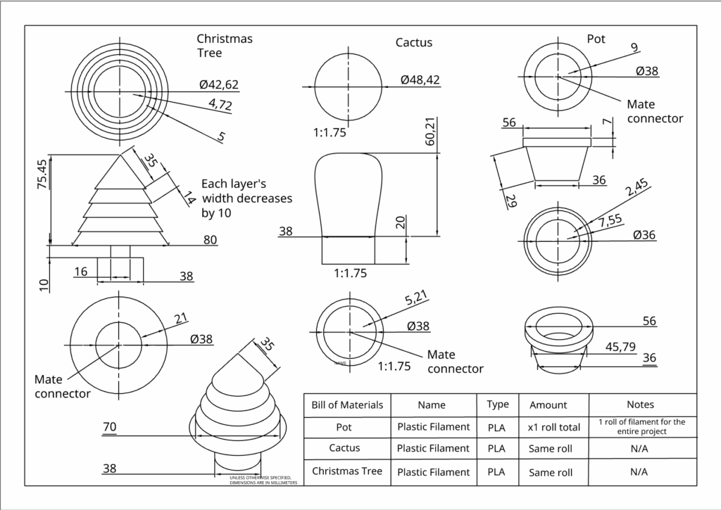
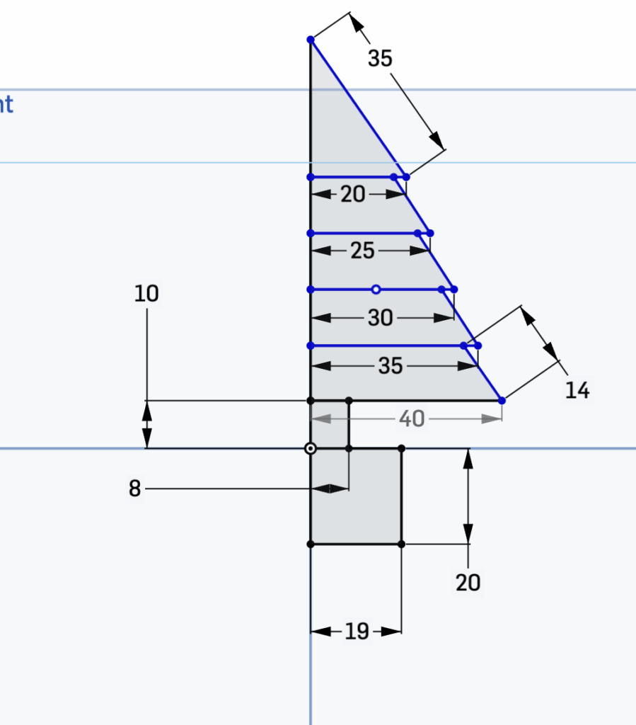
The overall process of creating this project can be divided into 3 main sections. The most important part of this design is the initial sketches. This sketch not only presents the shape of the plants and pot, but also maps out their dimensions to ensure each part connects with one another. The showcased example is a front-view sketch of the Christmas tree. On the bottom of the sketch, I decided to create an attachment block of standard dimensions (19 mm x 20 mm) that would fit into my pot hole. Each of the Christmas tree’s layers decrease by width incrementally, while maintaining a constant height. This helps to create symmetry in my design and ensures that the dimensions of the project would be easy to replicate by others viewing the mechanical drawing.
The next step of the project is to realize these sketches. This would be accomplished with two main tools, revolve and extrude. The revolve tool allows a user to select an axis from their sketch and create a 3D model by rotating the 2D sketch around the selected axis, until either it meets itself to create a ring shape or the user stops the revolve to create a shape similar to a slice of pie. This tool is helpful for designing circular models, such as in this case for the body of the cactus.
The second tool is to extrude the sketch, which creates a 3D model by extending a selected sketch with material to the front or back. This tool is especially useful for adding layers to a set sketch. This tool was used to create the attachment units connected to each plant. This second step creates 3D models for the sketches that can then be placed in assembly to review how each part interacts with one another. This interaction can be created using mates that connect the parts together, and can be seen in the mechanical drawings, as well as in the image below.
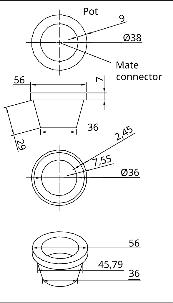
Lastly, a mechanical drawing and bill of materials are included. This drawing essentially builds a blueprint for the project. The purpose of a mechanical drawing is to allow others viewing the project to understand and be able to replicate the design, with the correct dimensions and scale. I decided to include the top, front, bottom, and isometric view for all 3 parts of my project.
The bill of materials serve a similar purpose, allowing a user to understand which materials they would need to replicate my design. Because I created the blueprint for a 3D printed project, my material only includes plastic filament of a specified type (PLA).
Ultimately, by combining my skills in sketching, extruding & revolving, assembly, and creating a mechanical drawing with a bill of materials, I was able to create a simple houseplant CAD design.
AI Usage Transcript
Attached below is a transcript of my AI usage. I did my best to understand each component of the AI’s suggestions and incorporate them into my designs.
Below is my full code, along with a video run-through of it.
### system setup ###
import pygame
# import pygame from Google Colab's storage into this project
import sys
# import "System", which allows interactions with the Python code itself and lets it access other modules such as pygame
import random
pygame.init()
# calls on the pygame module, as it's a function and prepares it to be used (similar to turning on a game console)


### game setup ###
SCREEN_WIDTH = 1000
SCREEN_HEIGHT = 500
# setting up variables for determining the display size.
# programming convention to use all caps for variables that will not change throughout the game
screen = pygame.display.set_mode((SCREEN_WIDTH, SCREEN_HEIGHT))
# pygame function that sets up a display based on given width and height in the parameters
clock = pygame.time.Clock()
# creates a clock in pygame, which will be used to set up the frame rate of the game
SPAWNPIPE = pygame.USEREVENT
# creates a special event, which will be used to create and delete pipes in intervals
pygame.time.set_timer(SPAWNPIPE, 600)
# Spawns a new pipe once every 1200 miliseconds (1.2 seconds)
score = 0
font = pygame.font.Font(None, 50)
# Simple scoring system based on survival time. In the parameters, "none" defines the default font, while "50" defines the font size

### game sprites ###
### bird ###
class Bird(pygame.sprite.Sprite):
    # creates a python class, which is used to define attributes of a sprite. The parameter inherits existing attribute definitions and features from pygame
    def __init__(self):
        # function where all the attributes of the bird sprite will be defined
        super().__init__()
        # call on the above-mentioned function to begin prepare for defining the attributes

        self.image = pygame.Surface((30, 30))
        # Create a blank surface for the circle (bird)
        self.image.fill((142, 184, 250))
        # Make the surface transparent
        pygame.draw.circle(self.image, (255, 255, 255), (15, 15), 15)
        # Draw a white circle with the defined attributes

        # to upload an image as the sprite for the bird
        self.rect = self.image.get_rect(center=(100, SCREEN_HEIGHT / 2))
        # short for rectangle, function that defines the position and size of the bird, can be used as a hitbox
        self.gravity = 0.25
        self.velocity = 0
        # defines the bird's weight and speed (at the start of the game)
    def update(self):
        # function to update the bird's position on the display every frame
        self.velocity += self.gravity
        # as the bird's gravity increases, its speed/velocity will increase with it
        self.rect.y += self.velocity
        # when the velocity is positive, the bird will be falling (negative change in y), and vice versa for negative velocity
        if self.rect.top < 0:
            self.rect.top = 0
            self.velocity = 0
        if self.rect.bottom > SCREEN_HEIGHT:
            self.rect.bottom = SCREEN_HEIGHT
            self.velocity = 0
        # ensures the bird does not fly off the screen. If its y position matches the top or bottom boundaries, the bird's velocity will be set to 0

    def flap(self):
        self.velocity = -4
        # When the bird flaps, the velocity will be set to negative, shooting the bird's y position up against gravity

# Create the bird
bird_group = pygame.sprite.GroupSingle()
# Creates a group that holds one sprite
bird = Bird()
bird_group.add(bird)
# adds the bird to the group


### pipes ###
class Pipe(pygame.sprite.Sprite):
    # similar to creating the bird sprite, with the difference that this sprite needs to ensure random spawn positions
    def __init__(self, x, y, position):
    # defines the x and y locations for the pipe, with the position parameter to determine whether the pipe is on the top or bottom
        super().__init__()
        self.image = pygame.Surface((50, 500))
        # creates a base for the sprite
        self.image.fill((0, 128, 0))
        # creates the pipe with the defined color

        # Determine the pipe's position and orientation
        self.rect = self.image.get_rect(midtop=(x, y))
        # short for rectangle, defines the dimensions and locations of the pipes. Get rect creates a rectangle the same size as the pipe
        if position == 'bottom':
            self.rect = self.image.get_rect(midtop=(x, y))
        # sets the middle-top of the pipe as the official "connecting point", aka the point the x and y locations will apply to
        if position == 'top':
            self.image = pygame.transform.flip(self.image, False, True)
            # Flips the top pipe vertically on the x-axis and creates a new sprite/pipe/rectangle in that new location
            # Ensures the top and bottom pipes are lined up
            self.rect = self.image.get_rect(midbottom=(x, y))
            # Changes the connecting point to the middle-bottom point of the rectangle to mirror the top pipe.

    def update(self):
        self.rect.x -= 6
        # Each frame move the pipe to the left by 3

# Create the pipes
pipe_group = pygame.sprite.Group()

running = True
while running:
    # Creates an infinite loop, as the while function requires a condition to be true to run, and "running" is currently set to true.
    # The code below will be repeated until running becomes false (when the player decides to quit)
    for event in pygame.event.get():
        # the "pygame.event.get" function collects all the user's actions during the loop, which lasts forever because of the while statement
        # used here to check for specific player inputs, but mainly closing the window
        if event.type == pygame.QUIT:
            running = False
        # if the user exits the window, the "running" variable will be set to false, stopping the while loop
        if event.type == pygame.KEYDOWN:
            if event.key == pygame.K_SPACE:
                bird.flap()
        # similar function to the first "event.type", checks if user performs an action.
        # If space bar is clicked, the flap function is called to set the bird's velocity to negative, launching it upwards
        if event.type == SPAWNPIPE:
            pipe_gap = 150
            # the gap between the two pipes that the bird can pass through
            pipe_y_pos = random.randint(150, 350)
            # random y position chosen by the random integer function. this position is the middle of the gap of the top and bottom pipes
            bottom_pipe = Pipe(SCREEN_WIDTH, pipe_y_pos + pipe_gap / 2, 'bottom')
            # the bottom pipe's parameters are defined. The x-axis is fixed, so set to screen width
            # the y-axis is random, thus uses the random integer function as the parameter. because this is the center point of the gap,
            # half of the total pipe gap is added to the y position to push the pipe down, creating a gap for the bird to fly through
            pipe_group.add(bottom_pipe)
            # add pipe to bottom pipe group
            # Create the top pipe
            top_pipe = Pipe(SCREEN_WIDTH, pipe_y_pos - pipe_gap / 2, 'top')
            pipe_group.add(top_pipe)
            # same logic as the bottom pipe, but inverse, and the pipe is added to the top_pipe group

    clock.tick(120)
    # calling on a function that determines the frame rate of a game. It is set to 120 fps for best tested performance
    screen.fill((142, 184, 250))
    # creates a background with a light blue color
    score = pygame.time.get_ticks() // 1000
    # built-in pygame timer. The // is used to divide the ticks by 1000 and provide an integer answer for easier display
    bird_group.draw(screen)
    # This draws the bird on the display
    bird_group.update()
    # Updates the bird on the display each frame
    pipe_group.draw(screen)
    pipe_group.update()
    # same as drawing the bird, displays the pipes on the screen and updates it each frame
    score_text = font.render(str(score), True, (0, 0, 0))
    # Drawing the text on the screen, and the str converts the score (which was an integer because of the "tick" function) to a string for pygame
    # the antialiasing and color defines the text attributes, specifically to make it look more natural and to define its color
    score_rect = score_text.get_rect(center=(SCREEN_WIDTH / 2, 50))
    # Creates a rectangle with the rect function for positioning the score
    screen.blit(score_text, score_rect)
    # overlays the one sprite on top of another, in this case being score on top of the rectangle that contains it
    if pygame.sprite.spritecollide(bird_group.sprite, pipe_group, False):
        running = False
        # built-in pygame function that checks for collision between the bird and the pipe group
        # If the collision happens, running is set to false, stopping the while loop

    pygame.display.flip()
    # A function that changes the front buffer with the back buffer.
    # Games prevent screen flicker by using a "front buffer" for the current display the user sees, and an invisible "back buffer" for drawing the next frame.
    # Once the back buffer is finished, it is moved to the front by the "flip" function, ensuring smooth visuals


pygame.quit()
sys.exit()
# quit pygame
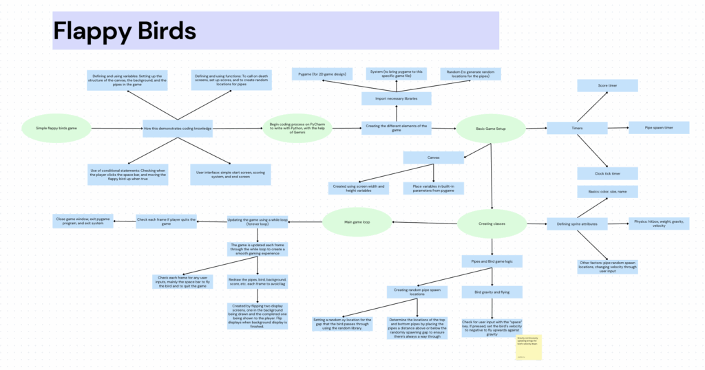
For my Fusion coding project, I created a Flappy Bird game using Python and the PyGame library. I chose this project because it is simple yet effectively demonstrates the required learning objectives, such as conditional statements (e.g., checking for spacebar inputs), the use of functions (e.g., bird physics, pipe generation), and making use of additional python libraries
I chose to create my coding project on PyCharm, as it is a tool specialized for Python coding, which was my chosen language. I first imported the necessary tools to my project, including “PyGame”, whose library included many built-in functions helpful to creating 2D games. Next, I imported “Random” as that would be core to creating pipes at different positions each time for my game. Lastly, importing the system allowed the python code (the file I was working in) to actually interact with the imported modules.
import pygame
import sys
import random
pygame.init()
# Calls on the PyGame library to prepare it for use

(Lines 1-8)
Next, I decided to build the game setup. The main use of this section was to set a few foundations which my game would be built upon. Notably, variables such as Screen_Width & Height determined the size of my canvas. With preset boundaries, these values could later be called on to position new sprites (such as the pipes).
The purposes of other variables, such as “clock”, “SpawnPipe”, “timer”, and “font-size” are self-explanatory. The game development is split into three main sections. Firstly, this “Game Set-up” section establishes the rules and the game environment before the actual gameplay loop begins. In short, it sets up variables that the later sections can call back on.
The next section of my code is the sprite creation. The main purpose of this section is to define how my game will look, which in this case is the flappy bird’s and the pipes’ dimensions and attributes. This section was a little complicated to code, but simple to explain. The first step was to define a sprite, before determining its dimensions and properties, and lastly considering whether it needed additional functions and if so, how it would affect the game logic later on.
self.image = pygame.Surface((30, 30))
       # Create a blank surface for the circle (bird)
       self.image.fill((142, 184, 250))
       # Make the surface transparent
       pygame.draw.circle(self.image, (255, 255, 255), (15, 15), 15)
       # Draw a white circle with the defined attributes
       # to upload an image as the sprite for the bird
       self.rect = self.image.get_rect(center=(100, SCREEN_HEIGHT / 2))
       # short for rectangle, function that defines the position and size of the bird, can be used as a hitbox

(Lines 37-46)
Lines like this, for example, create attributes for “self” (the bird) by setting a foundation, drawing a sprite on top of that, and adding an invisible rectangle beneath it to decide the bird’s position. Other lines such as gravity and velocity affect the physics of the game.
The last part of the code defines the central game logic. The most important line, the “While” loop, creates an infinite loop that ensures the game is updated each frame, so that the game functions smoothly internally and externally.
running = True
while running:
   # Creates an infinite loop, as the while function requires a condition to be true to run, and "running" is currently set to true.
   # The code below will be repeated until running becomes false (when the player decides to quit or loses)
   for event in pygame.event.get():
       # the "pygame.event.get" function collects all the user's actions during the loop, which lasts forever because of the while statement
       # used here to check for specific player inputs, but mainly closing the window
       if event.type == pygame.QUIT:
           running = False

(Lines 108-116)
Lines such as “for event in pygame.event.get():” collect all of the user’s actions while the game is running. Specific actions from this collection, mainly space bar clicks and ending the game, are then checked by codes such as “if event.type == blank”. If the condition is satisfied, then the following function would be performed. Aside from the major game logic, this section also facilitates minor but important parts of the game. For example, setting a background refreshes each frame and determining the fps of the game. The code ends with the functions “pygame.quit()” and “sys.exit()”
Ultimately, by combining setup, sprite design, and game logic, I believe I learned some of the necessary skills to build a complete and functional Flappy Bird game.
Gemini Usage Transcript
Below is the transcript of my AI usage. Although I experienced troubles in making AI provide lessons on how the code worked instead of writing it out for me, I’ve put in my best effort to understand each line. I have written comments in nearly every line of my code, explaining its function and purpose in the context, and I hope this demonstrates my comprehension. Alongside this, I have made edits to the code to alter its attributes as a way to show I understand the logic behind it.