Introduction
In this robotics project, I built a system that uses a servo motor and LEDs controlled by potentiometers through Arduino and Fusion. The goal was to make the motor move and lights react based on the input values from the sensors. The code reads and maps the analog signals from the potentiometers, then decides how the lights and motor should respond. I learned how coding connects with physical movement, how to use the Servo library, and how to debug and adjust the program to make everything work smoothly. This project helped me understand how sensors and code can work together to create smart, moving systems.
Design Explanation + Rules
Goal
Your task is to stop the fan (servo motor) by correctly adjusting two knobs (potentiometers) in the right sequence.
Instructions
Final stage
Once all stages are completed correctly, the Serial Monitor will display Open and Turn
This means the fan is unlocked and you have successfully completed the puzzle.
Start the game
When the circuit is powered, the LEDs will blink to show it is ready.
Identify the knobs
There are two knobs: left (A0) and right (A1).
You will need to turn these knobs to the correct positions in each step.
Observe the LEDs
There are three LEDs (pins 9, 10, and 11).
The LEDs will light up or flash to indicate progress or mistakes.
Adjust the knobs
Turn the knobs slowly and carefully to find the correct position.
The first correct combination will make certain LEDs turn on.
Advance through the stages
Each stage has a new combination.
Correct positions will change the LED patterns.
Move to the next stage once you see the correct LED signals.
Avoid traps
If the right knob (A1) is turned into the wrong range at the final stage, the system will reset and display a trap message.
You will need to start from the beginning if this happens.
AI Discussions + Inspirations
I have not used any sort of AI too much or at all for this project as it was not really that big of a help for me. I did take inspiration from people who are experts in Arduino and Tinkercad and from the extensive gallery available on TinkerCAD.
Conclusion
Through this robotics project in Fusion, I successfully developed and tested a moving motor system using code that controlled its movement and direction. Throughout the process, I learned how to decipher, troubleshoot, and optimize motor control code, as well as how small changes in programming can significantly affect the robot’s performance. This project helped me better understand the connection between coding and mechanical motion, strengthened my problem-solving skills, and gave me hands on experience with robotics design and programming integration. Overall, it was a valuable learning experience that deepened both my understanding in Coding in C++, and also my feel for more hardware related objects such as building the actual circuits and motors.
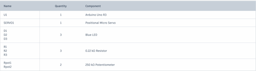
BOM:
Detailed Explanation of My Code
This device is like an electronic puzzle lock that reacts to two knobs, three LEDs, and a servo motor.
When you turn it on, the servo resets to 0 degrees and the LEDs flash a few times as a startup sequence. This shows that the system is awake and ready.
The two knobs are read continuously. Their positions are converted into a range that the Arduino understands so it can tell what positions are correct. Small messages appear in the serial monitor to show the knob positions.
Each knob has a corresponding LED. If a knob is turned to the correct range, its LED lights up. If not, the LED stays off. When both knobs are in the right positions at the same time, the device moves to the next stage.
The device has five stages, each with a different visual or movement effect. In the first stage, the LEDs blink with a soft signal to show that this step is correct. In the second stage, the LEDs blink faster to indicate progress. The third stage has another blink sequence to prepare for the main action. In the fourth stage, the LEDs alternate in a pattern, like a small light show. In the fifth and final stage, the servo reacts to the knob and the device can be fully “unlocked.”
There is also a trap check. If the wrong combination is tried at the final stage, the device resets itself. The LEDs turn off and the servo goes back to 0 degrees. This makes sure the game is not luck based.
In the last stage, turning one knob moves the servo as if you were turning a real lock mechanism. This makes the system interactive because your movements directly control the device.
- Variable Declarations
These lines create all the variables the code will use later:
int potD = 0;
int potE = 0;
int led1 = 0;
int led2 = 0;
int led3 = 0;
int i = 0;
int PDsup = 0;
int PDinf = 0;
int PEsup = 0;
int PEinf = 0;
int j = 0;
Each variable starts at 0. The word “int” means it stores a whole number. I use these variables to keep track of sensor readings, LED states, and any values I calculate while the program runs.
- Servo Library
This line tells the Arduino to load the Servo library, which allows the code to control servo motors. Without this, the servo commands wouldn’t work.
void loop()
After setup is done, the loop() function repeats over and over for as long as the Arduino is on. This is where the main logic of the project happens, like reading sensors, updating LEDs, and moving servos. Anything inside loop() runs continuously.
void setup()
This function runs one time when the Arduino starts up. Inside setup, I usually set pin modes, attach servos, and start serial communication.
The loop starts by reading the two knobs (A0 and A1). Their 0–1023 values get mapped into a range controlled by j and k, which change as the stages advance.
The program checks whether each knob is inside its current “target” range. If a knob is inside the correct interval (potD in PDinf–PDsup or potE in PEinf–PEsup), its corresponding LED state becomes 1. Otherwise it becomes 0. This is how the system knows if each knob is dialed correctly.
When both knobs hit their correct ranges at the same time, the system moves to the next stage. Each stage is represented by led3. Stage numbers go 1 → 2 → 3 → 4 → 5.
Stage transitions:
- Stage 1 to Stage 2: Both LEDs are 1. The program shrinks the knob range to 0–7, sets led 3 to 2, turns off all LEDs, and plays a fade-in/fade-out effect on LED pin 10.
- Stage 2 to Stage 3: Both LEDs are 2. The program sets new ranges (left knob 0–7, right knob around 173–180), switches led3 to 3, and blinks LED pins 9 and 11 five times.
- Stage 3 to Stage 4: Both LEDs are 3. LED pin 10 blinks ten times, led3 becomes 4, and the knob ranges change again (left ~153–160, right ~23–30).
- Stage 4 to Stage 5: Both LEDs are 4. The program switches led 3 to 5, updates ranges again (left ~85–93, right 0–7), and plays an alternating light pattern between LED pins 9, 10, and 11.
Final stage (led3 = 5): When both LEDs are 5, the system unlocks. ACESSO becomes HIGH, the knob mapping range becomes 0–90 for the servo, and potD starts controlling the servo. The program prints “OPEN” and asks you to turn the knob.
However, the other knob (potE) becomes a trap during this stage. If potE enters certain forbidden zones (0–40 or 50–89), the program prints “IT’S A TRAP!”, resets the servo to 0, resets the knob ranges, resets led3 to 1, turns off all LEDs, and the entire puzzle restarts from the beginning.
Finally, there is a short 10 ms delay to prevent the loop from running too fast.
Inside loop(), the Arduino constantly reads the two knobs and checks whether each one is turned into the correct range. If a knob is in the right spot, the program marks it as correct; if not, it resets that status. When both knobs are correct at the same time, the system moves to the next stage. Each stage tightens the knob ranges and displays a different LED pattern to show progress.
As the stages advance, the target ranges get narrower and the LED effects change. After passing through all four stages, the system reaches the final one, where turning one knob controls the servo. The other knob becomes a trap, if you move it into certain positions, the whole system resets and you have to start over.
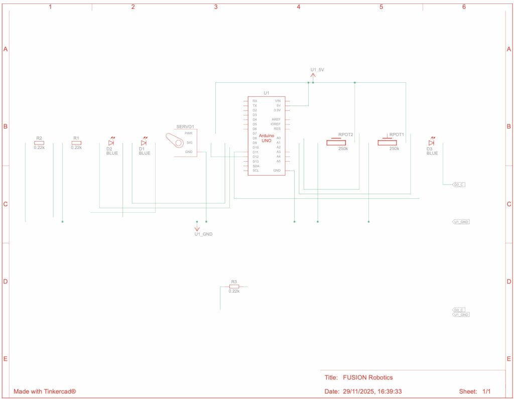
Circuit Diagram:
Leave a Reply to mcrompton Cancel reply