Patients with eczema suffer from it on a daily basis. Most importantly, they do not know how to effectively treat it. My project aims to incorporate both Machine Learning (ML) and Artificial Intelligence (AI) Models to help patients better diagnose and manage AD on a daily basis.
I will build a machine learning model to evaluate images to diagnose them with either “eczema” or “normal”. This will be done in Jupyter Notebook, Tensor flow. I will feed it extensive amounts of data that will act as a “train and test” set. After that, I will evaluate the machine against my definition statement by providing a different set of images called the validation set.
Progress Made:
Finished code for 3 models to compare and contrast results: Tensorflow, Random Forest, and SVM (Support Vector Machine)
Finished overall code for validation set (will print images and the accuracy of the machine)
Gathered a dataset of approximately 300 images.
Effectively utilized a large, pre built dataset to increase accuracy
Challenges:
Code not working as intended
Lack of data, decreases accuracy overall
Ethical concerns with pictures involved
Next Steps:
Gather more data (pictures)
Decide on a final model to use for production
Learn more about eczema by interacting with authentic dermatologists and specialists
AI Statement:
No AI was used in the production of this blog post, everything here was produced by myself.
My project aims to incorporate both Machine Learning (ML) and Artificial Intelligence (AI) Models to help patients better diagnose and manage AD on a daily basis.
What made me choose this as my Personal Project
I have been suffering from Atopic Dermatitis (Eczema) since moving to Canada. I was always perplexed as to why my skin was red and itchy in certain areas all day. Last year, my eczema was exacerbated substantially by the sea water (I fell into the water when tubing in Nanaimo during Summer) and the skin around my lips were crusting and there was yellow liquid oozing out. In addition, the itchiness led to pain, and that pain caused both physical and psychological issues. It hurt considerably and I realized from that point on that this was a serious issue. My major problem during those days in Nanaimo was that I did not know what to do about my condition at all. Therefore, I want to develop a user-friendly tool that can help others to better manage Atopic Dermatitis.
Background Research
Atopic Dermatitis is a chronic, inflammatory disease characterized by intense itchiness, dryness, and immune and skin barrier dysfunction, influenced by genetic and environmental factors. It affects 10-20 percent of people worldwide and 15-20 percent in Canada alone. AD significantly reduces quality of sleep due to both physical and psychosocial issues. Diagnosis and treatment can be tedious and time-wasting due to the necessity of a professional dermatologist. Because Atopic Dermatitis requires ongoing self care and the long-term application of certain ointments, many patients struggle with consistent self-treatment. This project aims to incorporate both Machine Learning (ML) and Artificial Intelligence (AI) Models to help patients better diagnose and manage AD on a daily basis.
Target Audience:
The potential target audience includes patients experiencing mild to moderate Atopic Dermatitis (Eczema).
Previous Ideas:
Designing questions that are answered well by common AI models (Chatgpt, Gemini etc) for patients to know what to ask and how to ask their questions
Integration of “Exposome” data, analyzing the things one is exposed to on a daily basis that may be a cause of atopic dermatitis
Can implement Psychological analysis on Atopic Dermatitis studies (Eczema has a huge effect on mental health in patients) Sentiment Analysis
Federated Learning can be used as well to maintain privacy
Automated treatment/feedback from AI
Prototype:
To develop the prototype, I need to accomplish 3 major milestones:
Develop a Machine Learning (ML) / Artificial Intelligence (AI) model for identifying Atopic Dermatitis (AD) from normal / healthy skin using images from smartphone camera
Enhance the ML / AI model with an additional images captured by another optical device (e.g., Wood’s lamp) and additional clinical / exposome data
Design a website or an app to allow users to use this ML/AI tool to manage their AD on a daily basis
Understand what Atopic Dermatitis is, why it is a major issue, and what are the technical and physical problems patients and physicians encounter today
Practice ML / AI model training using Tensorflow & Jupyter Notebook to create code for identifying AD vs healthy / normal skin using smartphone images
Develop skills for Python Coding (for later integration in Tensorflow)
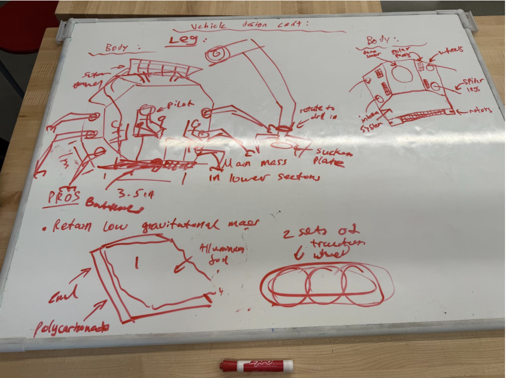
Try three different ML / AI models (such as random forest, convolutional neural network…etc.) to compare and contrast the performance (accuracy, precision, recall, and F1 score)
Increase amount of photos in training (50 per skin condition) and testing (20 per skin condition) datasets
Phase 2 (March 10 — March 25)
Increasing Model Complexity
Enhance the ML / AI model with an additional images captured by another optical device (e.g., Wood’s lamp) and additional clinical / exposome data
Increasing Database
Utilize public datasets such as Ham10000 or ISIC Archive to further train the ML AL model for better AD prediction
Phase 3 (March 25 — April 10)
Enhance the ML / AI Model and Build the Prototype
Train a Convolutional Neural Network (CNN) to identify AD (Atopic Dermatitis) and its severity in pictures provided (Using Jupyter Notebook)
NLP/Sentiment Branch: Build a transformer based model to analyze patient “mental health” markers based on their description of symptoms
Combine both Vision and NLP into a single output layer: Predicted_SCORAD=f(Image_Features,Patient_Sentiment,Exposome_Data)
Design a website / app to allow users to use this ML/AI tool to manage their AD on a daily basis
Phase 4 (April 10 — May 1)
Testing and Validation
Validation Test: Run model against “Gold Standard” (Accurate diagnosis from dermatologist specializing in Atopic Dermatitis)
Testing the Models: Testing how the Models handle different skin tones and lighting conditions to ensure equity and accuracy
Other Factors: Determine which Exposome factors have the biggest influence on the flaring of atopic dermatitis
The Planetary Exploration Project is an opportunity for students to present a self-designed vehicle suitable for travel on exoplanets. Our group was assigned the exoplanet Teegarden’s Star B. Due to the rocky terrain and uneven climate, it was our goal to develop a vehicle using tools such as TinkerCAD, Onshape, and code that can safely travel on the planet. Our initial definition statements were:
How might four human astronauts travel on the surface of Teegarden’s Star b in the most efficient and safe way possible?
Four human astronauts need a safe and efficient way to travel on the surface of Teegarden’s Star b because it is an unknown exoplanet which possesses a unique environment separate from Earth.
Feedback/Things to consider:
Distance?
Give enough information about the question without overcomplicating it
The definition should be testable via the vehicle prototype (includes parameters etc)
Relate constraints to safety and efficiency
Make it less wordy, clearer, concise
After discussing as a group during class, and redefining a few criteria that needed to be met, this is our revised definition statement:
Four human astronauts need a safe and efficient way to travel 10 continuous km across Teegarden’s Star b due to unique atmospheric, gravitational, and geological conditions. We must overcome challenges (such as a differing gravitational pull, rocky terrain, and uncertain atmosphere) by creating a testing environment that models these conditions.
(Clarification: This work was produced by me, Tiger, and Hukam and can be seen in this document)
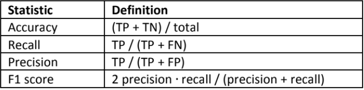
Initially, we worked to define a list of possible ideas that would address the task defined. This was an opportunity for us to simply brainstorm and take into consideration all the possible, multifaceted ways this problem could be addressed. Our works during this class can be seen here:
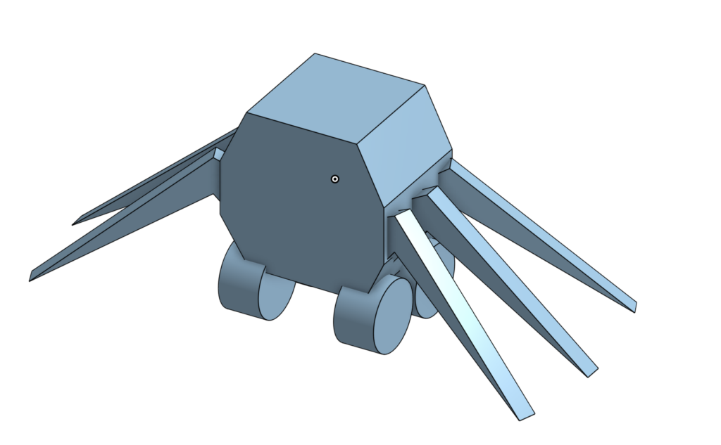
This was a planning board basically sketching out how we wanted the vehicle to look like (such as the wheels indicated on the left and the spider legs on the right)
Next, we eliminated all the ideas that would simply not be possible such as: No gas, No food or water, No engine etc. Now, having ruled out multiple ideas that would not be feasible, the ones that were left sounded like a decent idea. Therefore, our goal now was to choose or combine the remaining ideas that would be best suited for addressing the problem. First, we split the ideal model into several distinct concepts: Mobility, comfortability, and feasibility. Mobility: Can the vehicle move successfully across Teegarden’s Star B. Comfortability: Can 4 astronauts physically survive 10km in the vehicle on Teegarden’s Star B. Feasibility: Are we going to be able to model this vehicle as a prototype and simulate the conditions on the planet using available materials. Our initial idea was to define 4 or 2 vehicles where the astronauts would be split into groups of 2 or 1/vehicle; Our idea behind this was to decrease energy usage and increase speed without detriments.
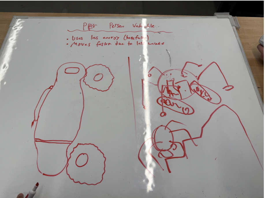
Second, we brainstormed what features the vehicle needed for it to be able to safely traverse the terrain on Teegarden’s Star B. A major part of this section was deciding what lower “body” parts the vehicle would possess. Ultimately, our goal was to have tracks, wheels, and spider-like legs that would rotate whenever needed. The key functions shown at the top of the board indicate the criteria we had to meet: Traction, stability on gravity; No flipping on rocky terrain; Operate with/without atmosphere; Protection against radiation; Powerful, endurance. Below are attempts of the portrayal of a hover system to help the spider legs and tracks from interchangeably switching depending on current terrain.
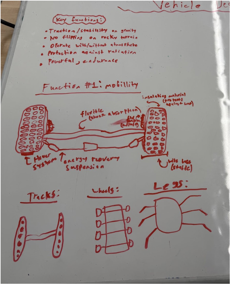
Third, we hypothesized what features the main body of the vehicle have to possess for it to be succinctly ready for the harsh environments on Teegarden’s Star B. We mapped out the exact dimensions of each part of the vehicle (body, leg etc) and visualized how it would work after connecting each part. At the bottom, we wrote down the pros and cons of each design discussed (retains low gravitational centre, less expensive, etc):
After all this was done, our group decided to make a coherent BOM list (included later in the blog post) so that both us and the teacher would have a general idea of the items needed to be ordered.
Continued Actions
Along with the CAD Design, I believed it was necessary to pair the vehicle with certain code. Although we did not end up using this code as Tiger had a pre-built vehicle (completed in Robotics) that utilized batteries and previously included code, this was my code (coded in Java using online.gbd):
System.out.println(“CRITICAL: Temperature out of range.”);
Systems.disableAllNonEssential();
}
private static void attemptReconnect() {
System.out.println(“WARNING: Communication lost. Reconnecting…”);
Communications.resetAntenna();
}
private static void logStatus(double b, double t, boolean c) {
System.out.println(
“Battery: ” + b + “% | Temp: ” + t + “C | Comms: ” + c
);
}
private static void sleep(int ms) {
try {
Thread.sleep(ms);
} catch (InterruptedException e) {
}
}
}
Videos of First Test
On the 18th of December, our group completed the first test of our vehicle using a meter stick, a wood surface and a stationary camera to record its movement. Artificial items were utilized in an attempt to simulate the authentic conditions on Teegarden’s Star B (Clay, rocks, paper). Our Test Motive was: To see if the vehicle works and if it can climb over obstructions.
Results:
Worked
Most of the time, the car would drive forward, and the wheels would work.
The car can stop really quickly by just turning the battery source off.
Problems
The back left wheel does not touch the ground enough, and thus sometimes doesn’t spin, causing the vehicle to always turn left and crash.
The vehicle has no way, at the moment, to climb any objects with height.
There is no way to control the movement of the vehicle other than to turn it on and move forward
When we used paper balls as objects, the wheels got stuck on them. (The friction of paper likely slowed the vehicle down)
Sometimes the car just spins in a circle and doesn’t move. I noticed this was because the back left wheel was completely off the ground.
I had to hold the battery pack and walk as the vehicle moved. We have no way of turning the vehicle on and off from a distance.
Possible Improvement
Make the back left wheel taller by adding some cardboard or more foam to where it’s connected.
We can get bigger front wheels to give the car a slant, which could maybe help it climb better.
Add a way to make the vehicle climb mountains (Spider leg idea could work, but it’s very hard, we can discuss this issue later)
Add a DC motor control to the car so then we can use a remote to control how the car moves from a distance.
On the 23rd of January, our group completed the second and final test to assess the performance of our vehicle in simulated terrain similar to that of Teegarden’s Star B’s. Unfortunately, due to the massive amount of changes we decided to make to the vehicle (such as including a full suspension system, and using bluetooth to remotely control it), it did not function as we would have liked in the second test. In reality, it barely moved on the rough surface provided. However, we did get a measure of the voltage (0.99V) and this is analyzed in the “Testing results and efficiency”.
Goals for this Test: To finally assess whether or not our designed vehicle is suitable for traverse on Teegarden’s Star B
Outcomes: Vehicle did not move, failed test
What worked: Got a measure of voltage of 0.99V, indicating very low energy efficiency, which explains why the vehicle failed to move.
To analyze the electrical efficiency of the vehicle, we compared the voltage supplied by the batteries to the voltage effectively delivered to the motors during testing. Each alkaline AA battery provides approximately 1.5 V. Since four batteries were used in series, the total input voltage to the system is:
Equation 1:
During testing, the measured voltage delivered to each motor fluctuated between 0.6 V and 0.9 V. To account for this variation, the average motor voltage is calculated:
Equation 2:
Because the vehicle uses four motors operating simultaneously, the total effective output voltage delivered to the motors is:
Equation 3:
Energy efficiency is defined as the ratio of useful electrical output to the total electrical input. This relationship is expressed as:
Equation 4:
Substituting the calculated values:
Equation 5:
This series of calculations exemplify the low percentage of energy efficiency. This is likely due to the unnecessary complication and incorrect displacement of the wires inside the vehicle. Because of this low energy efficiency, the vehicle was not able to move and therefore was deemed “unworthy” of traversal on Teegarden’s Star B.
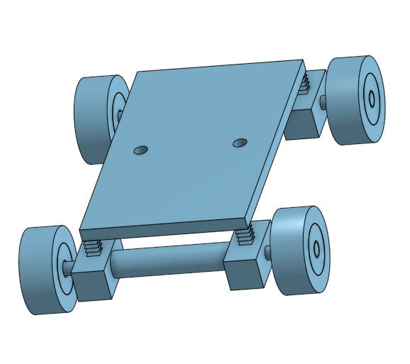
CAD Designs
This is CAD design we decided to go with for testing
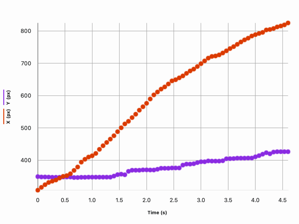
Vernier Analysis
The Vernier Graph Analysis shows the position of the vehicle recorded in the video with respect to its x and y positions. In this analysis, the x-position increases steadily from approximately 320 px to 820px within 4.5 seconds, indicating that the vehicle was able to move forward relatively consistently across the test. This suggest that the drive motion was functional and that the vehicle was capable of moving forwards on relatively flat terrain.
In contrast, the y position shows only a small overall increase, rising gradually from around 350 px to approximately 430 px. This limited change indicates that the vehicle experienced minimal vertical displacement, meaning it struggled to climb or navigate elevation changes (the paper balls and the rock + clay presented as obstacles in the test). The relatively shallow slope of the y proponent of the graph supports the claim that the vehicle struggled to traverse over obstacles such as the clay rock, and the paper balls presented to emulate the mountains on Teegarden’s Star B.
BOM
Bill of Materials (BOM)
Category
Component / Material
Quantity
Purpose / Justification
Structural
Foam board
3 sheets
Used for the main chassis due to its lightweight nature and ease of cutting and shaping.
Structural
Wooden dowels
6
Provided structural reinforcement and axle support for wheels and legs.
Structural
HDPE plastic sheet
1
Used to simulate durable outer plating and improve rigidity.
Mobility
Rubber wheels
4
Allowed ground traction and forward motion on flat terrain.
Mobility
Rubber treads
2 strips
Improved grip on uneven and sandy surfaces.
Mobility
Cardboard (terrain testing)
Multiple pieces
Used to simulate uneven terrain and elevation changes.
Electronics
DC motors
2
Converted electrical energy into mechanical motion for propulsion.
Electronics
Motor driver module
1
Controlled motor direction and speed.
Electronics
Battery pack (7.4 V)
1
Primary power source for the vehicle.
Electronics
Battery holder
1
Secured the battery and ensured stable electrical connections.
Electronics
HC-05 Bluetooth module
1
Enabled wireless communication for remote control.
Electronics
Arduino microcontroller
1
Acted as the control unit for motor operation and communication.
Wiring
Jumper wires
Multiple
Connected electrical components and circuits.
Testing & Simulation
Clay
Multiple blocks
Simulated large “mountains” and high-resistance terrain.
Testing & Simulation
Kinetic sand
1 tray
Simulated loose planetary soil conditions.
Testing & Simulation
Foam rocks
Several
Simulated rocky obstacles.
Assembly
Hot glue
Several sticks
Used to assemble structural components quickly.
Assembly
Tape
1 roll
Temporary mounting and reinforcement during testing.
Evaluation
Overall, I believe the project was generally well planned and tested. However, there were several issues that if addressed, would have improved the outcome of the last test significantly. First, our initial idea of using spider legs to elevate the vehicle to traverse rocky terrain was extremely ambitious and in hindsight, a risky endeavour. Due to all the time our group spent on that idea, we did not allocate sufficient time to building the actual vehicle. Second, we should have definitely tested our prototype more often than the two “Test days” provided to us. This would have aided us to evaluate the current condition of the vehicle and areas it needs improvement in. Third, instead of telling a single person to a single task (Tiger — CAD + Robotics, Hukam — Documentation + CAD, Daniel — Code + Mathematical Computation), I think we should have combined the knowledge of all 3 people in our group on every task. This would have increased the contributions of all 3 people and everyone would be in unison of the final conclusions.
Realistically, a vehicle with 50 percent efficiency would travel up to 1600km on an average gas of tank on earth. Although 50 percent efficiency is not disappointing at all, the main focus of the design project was to design a vehicle that is suitable for travel on the rugged terrain of Teegarden’s Star B. Therefore, although the vehicle will travel sufficiently far on land, it will struggle to navigate difficult terrain on an exoplanet with 50 percent efficiency. To ensure its stability and consistency on Teegarden’s Star B, I need to ensure that the gas tank it will run on will not leak or get impaired by the harsh environments on the exoplanet. I can achieve this by multiple rounds of testing on Earth with simulated environments to ensure the area where the gas tank will be located on the vehicle is safe and protected from environmental issues.
I chose Teegarden’s Star b because it’s one of the closest similar Earth mass exoplanets we’ve found only situated about 12.5 lightyears away, and its size and energy intake makes it one of the more realistic places where liquid water could exist. But choosing a “potentially habitable planet” is only the beginning. If we were ever to send people there, the environment around the Planet would affect our every decision. Its radiation, stellar activity, and orbital conditions all affect how a vehicle must be designed and protected. That’s why we looked at real spacecraft systems and shielding strategies: understanding how current spaceships or rovers survive harsh conditions helps me imagine a vehicle that could actually keep its occupants safe on a journey this long.
Opportunities
Teegarden’s Star b provides opportunities due to its Earth like mass, which means gravity could feel familiar and manageable for human life. Because it receives a similar amount of starlight to Earth, the planet may be able to maintain liquid water and a temperate climate if it has a stable atmosphere. Its close orbit around a faint star could also allow for efficient power generation using infrared optimized solar technology. Overall, it presents a promising environment for scientific exploration and potential colonization.
Challenges
One major challenge is that the planet orbits extremely close to its small star, making tidal locking highly likely meaning one side may be in permanent daylight while the other remains dark. This could create extreme temperature differences and atmospheric instability. Red dwarf stars also emit strong solar flares and radiation that could strip away a planet’s atmosphere. Because the planet does not transit its star, we still do not know its radius, atmosphere, or true surface conditions, adding large uncertainties to any colonization plans.
Vehicle Design
Designing a vehicle for a journey to Teegarden’s Star b means preparing for an environment harsher than anything experienced on Earth. The ship isn’t just used for transportation, it is the only barrier between the crew and constant radiation, freezing temperatures, micrometeoroids, and complete isolation.
Radiation is one of the biggest threats in deep space. Without Earth’s magnetic field or atmosphere, the crew would be exposed every day, so the vehicle needs several layers of protection. Hydrogen rich materials like water or polyethylene can be placed around the living areas to block high energy particles. Using a layered combination of lighter and heavier materials helps reduce different kinds of radiation without creating harmful secondary effects. The ship would also need a small, heavily protected “storm shelter” where the crew could stay during bursts of radiation from the star. Even basic elements of the ship, like water tanks or fuel storage, can be arranged around the cabin to add extra shielding without adding much mass.
The structure of the vehicle also has to survive meteoroid impacts and major temperature swings. Materials such as aluminum lithium alloys, carbon composites, and multi layer insulation help the outside of the ship stay both strong and lightweight.
Power and reliability are another major challenge. Because a mission like this would last decades, all systems need to be redundant, modular, and able to withstand years of radiation exposure. This is one reason I looked at the computers used on missions like the Mars rovers. They show how engineers design hardware that keeps working in extreme conditions and gave me ideas about how similar systems could be protected on our vehicle.
How?
Scientists discovered Teegarden’s Star b using the radial velocity method , where precision spectrographs like CARMENES detect tiny wobbles in the star caused by orbiting planets. Follow-up observations from instruments such as ESPRESSO, MAROON-X, and TESS refined the planet’s orbital period (4.9 days), minimum mass (approx 1.1 Earth masses), and its possible position in the habitable zone. Climate models and computer simulations have explored whether it could support liquid water. The main scientific reports detailing this are Zechmeister (2019), whom first announced the discovery, and Dreizler (2024), whom revisited the system with newer data.
Conclusion
Teegarden’s Star b stands out as a realistic but challenging candidate for future exploration or settlement. Its Earth like mass and position near the habitable zone offer promising opportunities, yet its close orbit, possible tidal locking, and uncertain atmosphere require advanced engineering solutions. The vehicle design formulas covering radiation shielding, power generation, and torque requirements highlight at how scientific principles guide every part of mission planning. Although many conditions remain unknown, the research methods used to study the planet provide increasingly precise data, allowing us to design smarter, safer systems for operations on a world so different from our own.
Boukrouche, R., Caballero, R., & Lewis, N. T. (2025). Near the runaway: The climate and habitability of Teegarden’s Star b. The Astrophysical Journal Letters, 993(1), L19–L19. https://doi.org/10.3847/2041-8213/ae122a
Zechmeister, M., Dreizler, S., Ribas, I., Reiners, A., Caballero, J. A., Bauer, F. F., Béjar, V. J. S., González-Cuesta, L., Herrero, E., Lalitha, S., López-González, M. J., Luque, R., Morales, J. C., Pallé, E., Rodríguez, E., Rodríguez López, C., Tal-Or, L., Anglada-Escudé, G., Quirrenbach, A., & Amado, P. J. (2019). The CARMENES search for exoplanets around M dwarfs. Astronomy & Astrophysics, 627, A49. https://doi.org/10.1051/0004-6361/201935460
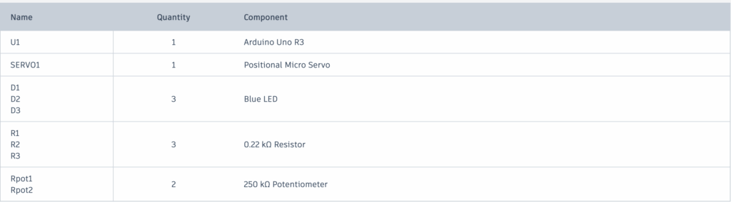
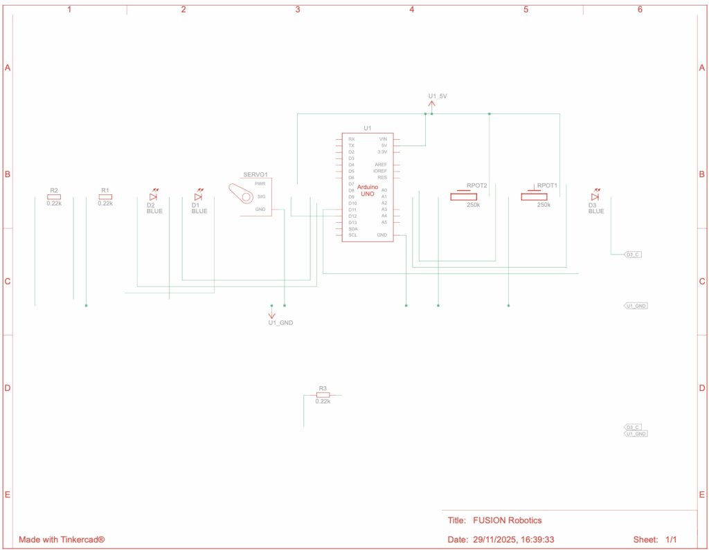
In this robotics project, I built a system that uses a servo motor and LEDs controlled by potentiometers through Arduino and Fusion. The goal was to make the motor move and lights react based on the input values from the sensors. The code reads and maps the analog signals from the potentiometers, then decides how the lights and motor should respond. I learned how coding connects with physical movement, how to use the Servo library, and how to debug and adjust the program to make everything work smoothly. This project helped me understand how sensors and code can work together to create smart, moving systems.
Design Explanation + Rules
Goal Your task is to stop the fan (servo motor) by correctly adjusting two knobs (potentiometers) in the right sequence.
Instructions
Final stage Once all stages are completed correctly, the Serial Monitor will display Open and Turn This means the fan is unlocked and you have successfully completed the puzzle.
Start the game When the circuit is powered, the LEDs will blink to show it is ready.
Identify the knobs There are two knobs: left (A0) and right (A1). You will need to turn these knobs to the correct positions in each step.
Observe the LEDs There are three LEDs (pins 9, 10, and 11). The LEDs will light up or flash to indicate progress or mistakes.
Adjust the knobs Turn the knobs slowly and carefully to find the correct position. The first correct combination will make certain LEDs turn on.
Advance through the stages Each stage has a new combination. Correct positions will change the LED patterns. Move to the next stage once you see the correct LED signals.
Avoid traps If the right knob (A1) is turned into the wrong range at the final stage, the system will reset and display a trap message. You will need to start from the beginning if this happens.
AI Discussions + Inspirations
I have not used any sort of AI too much or at all for this project as it was not really that big of a help for me. I did take inspiration from people who are experts in Arduino and Tinkercad and from the extensive gallery available on TinkerCAD.
Conclusion
Through this robotics project in Fusion, I successfully developed and tested a moving motor system using code that controlled its movement and direction. Throughout the process, I learned how to decipher, troubleshoot, and optimize motor control code, as well as how small changes in programming can significantly affect the robot’s performance. This project helped me better understand the connection between coding and mechanical motion, strengthened my problem-solving skills, and gave me hands on experience with robotics design and programming integration. Overall, it was a valuable learning experience that deepened both my understanding in Coding in C++, and also my feel for more hardware related objects such as building the actual circuits and motors.
This device is like an electronic puzzle lock that reacts to two knobs, three LEDs, and a servo motor.
When you turn it on, the servo resets to 0 degrees and the LEDs flash a few times as a startup sequence. This shows that the system is awake and ready.
The two knobs are read continuously. Their positions are converted into a range that the Arduino understands so it can tell what positions are correct. Small messages appear in the serial monitor to show the knob positions.
Each knob has a corresponding LED. If a knob is turned to the correct range, its LED lights up. If not, the LED stays off. When both knobs are in the right positions at the same time, the device moves to the next stage.
The device has five stages, each with a different visual or movement effect. In the first stage, the LEDs blink with a soft signal to show that this step is correct. In the second stage, the LEDs blink faster to indicate progress. The third stage has another blink sequence to prepare for the main action. In the fourth stage, the LEDs alternate in a pattern, like a small light show. In the fifth and final stage, the servo reacts to the knob and the device can be fully “unlocked.”
There is also a trap check. If the wrong combination is tried at the final stage, the device resets itself. The LEDs turn off and the servo goes back to 0 degrees. This makes sure the game is not luck based.
In the last stage, turning one knob moves the servo as if you were turning a real lock mechanism. This makes the system interactive because your movements directly control the device.
Variable Declarations These lines create all the variables the code will use later:
int potD = 0; int potE = 0; int led1 = 0; int led2 = 0; int led3 = 0; int i = 0; int PDsup = 0; int PDinf = 0; int PEsup = 0; int PEinf = 0; int j = 0;
Each variable starts at 0. The word “int” means it stores a whole number. I use these variables to keep track of sensor readings, LED states, and any values I calculate while the program runs.
Servo Library This line tells the Arduino to load the Servo library, which allows the code to control servo motors. Without this, the servo commands wouldn’t work.
void loop() After setup is done, the loop() function repeats over and over for as long as the Arduino is on. This is where the main logic of the project happens, like reading sensors, updating LEDs, and moving servos. Anything inside loop() runs continuously.
void setup() This function runs one time when the Arduino starts up. Inside setup, I usually set pin modes, attach servos, and start serial communication.
The loop starts by reading the two knobs (A0 and A1). Their 0–1023 values get mapped into a range controlled by j and k, which change as the stages advance.
The program checks whether each knob is inside its current “target” range. If a knob is inside the correct interval (potD in PDinf–PDsup or potE in PEinf–PEsup), its corresponding LED state becomes 1. Otherwise it becomes 0. This is how the system knows if each knob is dialed correctly.
When both knobs hit their correct ranges at the same time, the system moves to the next stage. Each stage is represented by led3. Stage numbers go 1 → 2 → 3 → 4 → 5.
Stage transitions:
Stage 1 to Stage 2: Both LEDs are 1. The program shrinks the knob range to 0–7, sets led 3 to 2, turns off all LEDs, and plays a fade-in/fade-out effect on LED pin 10.
Stage 2 to Stage 3: Both LEDs are 2. The program sets new ranges (left knob 0–7, right knob around 173–180), switches led3 to 3, and blinks LED pins 9 and 11 five times.
Stage 3 to Stage 4: Both LEDs are 3. LED pin 10 blinks ten times, led3 becomes 4, and the knob ranges change again (left ~153–160, right ~23–30).
Stage 4 to Stage 5: Both LEDs are 4. The program switches led 3 to 5, updates ranges again (left ~85–93, right 0–7), and plays an alternating light pattern between LED pins 9, 10, and 11.
Final stage (led3 = 5): When both LEDs are 5, the system unlocks. ACESSO becomes HIGH, the knob mapping range becomes 0–90 for the servo, and potD starts controlling the servo. The program prints “OPEN” and asks you to turn the knob.
However, the other knob (potE) becomes a trap during this stage. If potE enters certain forbidden zones (0–40 or 50–89), the program prints “IT’S A TRAP!”, resets the servo to 0, resets the knob ranges, resets led3 to 1, turns off all LEDs, and the entire puzzle restarts from the beginning.
Finally, there is a short 10 ms delay to prevent the loop from running too fast.
Inside loop(), the Arduino constantly reads the two knobs and checks whether each one is turned into the correct range. If a knob is in the right spot, the program marks it as correct; if not, it resets that status. When both knobs are correct at the same time, the system moves to the next stage. Each stage tightens the knob ranges and displays a different LED pattern to show progress.
As the stages advance, the target ranges get narrower and the LED effects change. After passing through all four stages, the system reaches the final one, where turning one knob controls the servo. The other knob becomes a trap, if you move it into certain positions, the whole system resets and you have to start over.
For my CAD project, I decided to create a design of a robot arm in Onshape. As a beginner, I was new to the world of computer aided design, so I relied on AI tools such as Notebook LM and ChatGPT to guide me and help me learn the basic functions and techniques. By using these tools, I was able to explore sketching, extruding, and shaping 3D objects, gradually building my skills while completing the project. This experience not only introduced me to the fundamentals of CAD but also allowed me to see how AI can support learning and problem-solving in design.
As Thomas Edison once said, “Genius is one percent inspiration and ninety-nine percent perspiration,” and this project showed me how effort combined with guidance can lead to meaningful and powerful results.
Reflections
Working on this CAD project in Onshape was a really awesome experience for me. At the start, I was a complete beginner and didn’t know where to begin, but by using AI and tutorials, it really helped me figure out the basics step by step. I learned not just how to use the tools, but also how to think like a designer, planning, testing ideas, and improving my work along the way. It was exciting to see my sketches turn into real 3D models, and even more satisfying to solve problems I didn’t know I could. Overall, this project taught me patience, creativity, and the value of learning through trial and error, and it definitely makes me feel more confident about exploring CAD in the future.
For my CAD project, I designed a robot arm using Onshape. I started by sketching the main parts of the arm, such as the base, joints, and segments, making sure all the dimensions were accurate. Then, I used the extrude tool to turn those sketches into 3D parts. Once all the pieces were finished, I assembled them using different mates such as the revolute mate (which makes the different pieces stick together) to make sure the arm could move realistically.
After completing the assembly, I created a detailed mechanical drawing that included important dimensions and a Bill of Materials listing all the parts. This project helped me understand how sketching, extruding, and assembling come together to create a working design, and it showed me how important precision and planning are in mechanical design.
To add on to my “Ai Discussions” panel, I have used more tutorials on platforms such as YouTube as I found those easier to comprehend and to follow along with in comparison to asking NotebookLM or other AI websites. A great example of this would be when I was confused about where the extrude button was, and Gemini’s Descriptions were not as useful as the immersive tutorials online.
“Programs must be written for people to read, and only incidentally for machines to execute.” — Harold Abelson
Welcome to my first coding project! This project signifies the beginning of my journey into programming and computational knowledge with the language of Python. As someone new to Python coding, I am excited to explore the immense potential of Python, a versatile and beginner friendly language. I will use these skills to solve problems and create meaningful programs.
Throughout this project, I aim to develop my understanding of basic programming concepts such as variables, loops, conditionals, and functions, while also nurturing curiosity, persistence, and logical thinking. I hope that this piece of work not only demonstrates my learning progress but also reflects my passion for technology and STEM in general.
As Steve Jobs once said, “Everybody in this country should learn to program a computer… because it teaches you how to think.” With that in mind, this project is my first step toward thinking like a programmer, embracing challenges, and building skills that will last my lifetime.
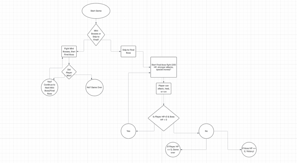
This is my flowchart that describes how my program runs and works. It also includes parts of my thought process when I initially decided to create this game.
Explained in Detail
This Python program is a text-based adventure game that runs entirely in the console. It uses functions and loops to create an interactive battle system.
The player controls a hero with stats like HP, level, XP, and gold, all stored in the code. You can choose to rest, explore, or quit. Resting increases HP and decreases your special attack cooldown. Exploring triggers a random encounter with an enemy, selected from a list using the random module. Each enemy also has its own dictionary containing its name, HP, and attack power.
During battle, a while loop does the combat every turn. You can pick from three actions: attack, special, or run. Regular attacks deal random damage using random.randint(), while special attacks are stronger but it requires waiting a few turns before you can reuse it. Enemies also attack each round, and their damage is randomly calculated within a range.
When an enemy is defeated, you earn random amounts of XP and gold. If your XP exceeds a threshold (which is based on your level), you level up, your HP refills, and the game gets progressively harder. The program keeps track of all defeated enemies, and once you’ve beaten them all, you’ll face the final boss, the Dragon.
If your HP drops to zero, the game ends with a “Game Over.” Beating the Dragon prints a victory message and ends the main game loop.