Intro / Abstract:
TRAPPIST-1e is one of Earth’s best opportunities for a home beyond Earth. It is a rocky planet with a density very similar to Earth, located about 40 light years away from Earth. Because of the distance from the planet to its star, TRAPPIST-1, it lies in an area called the Habitable Zone. This zone is special because it means there is a higher likelihood of liquid water being present on the planet.
In order to take advantage of this we must build a vehicle to travel through the planet. So we narrowed down the project into one statement.
The Definition Statement
We need to build a vehicle that can withstand TRAPPIST-1e’s extreme contrasting temperatures, traverse the uneven and rocky terrain, and endure the immense radiation emitted by TRAPPIST-1e’s star. Additionally, the vehicle must be large enough to hold at least four individuals and have enough fuel to travel 10km, unless powered by another source such as advanced radiation solar power.
We spent a few days looking over this idea in order to decide how we would go about this process. We focused on one main part of this prompt that is possible to test in Earth’s atmosphere: uneven rocky terrain.
Below is our whiteboard where we drafted many ideas for our vehicle.
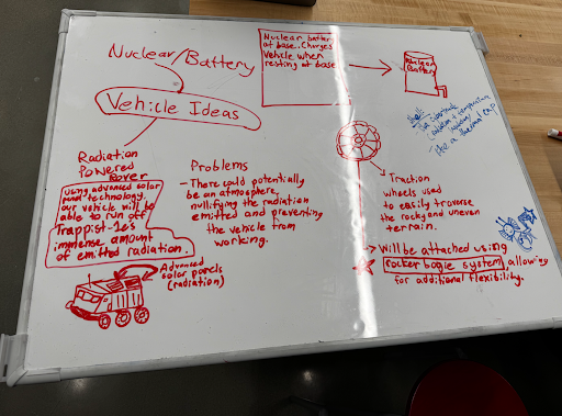
Radiation Powered Rover
We thought of harnessing TRAPPIST-1’s powerful radiation with special solar panels in order to power the vehicle. We identified the problem that the atmosphere of TRAPPIST-1e would significantly reduce the radiation.
Rocker-Bogie System
We saw on the Mars rover, they use a special suspension called the Rocker-Bogie system, which is very good at climbing tall hills and uneven surfaces.
Traction Wheels
We decided to use traction wheels in order to have a strong grip on the rocky, uneven terrain our vehicle would have to drive on during its voyages.
Method / Procedure:
Once we had imagined our vehicle, we started to make the CAD design for it. We went through several designs and iterations before we had figured out what design we would use.
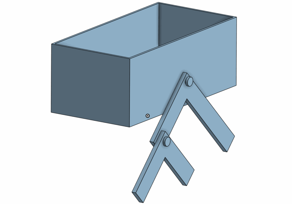
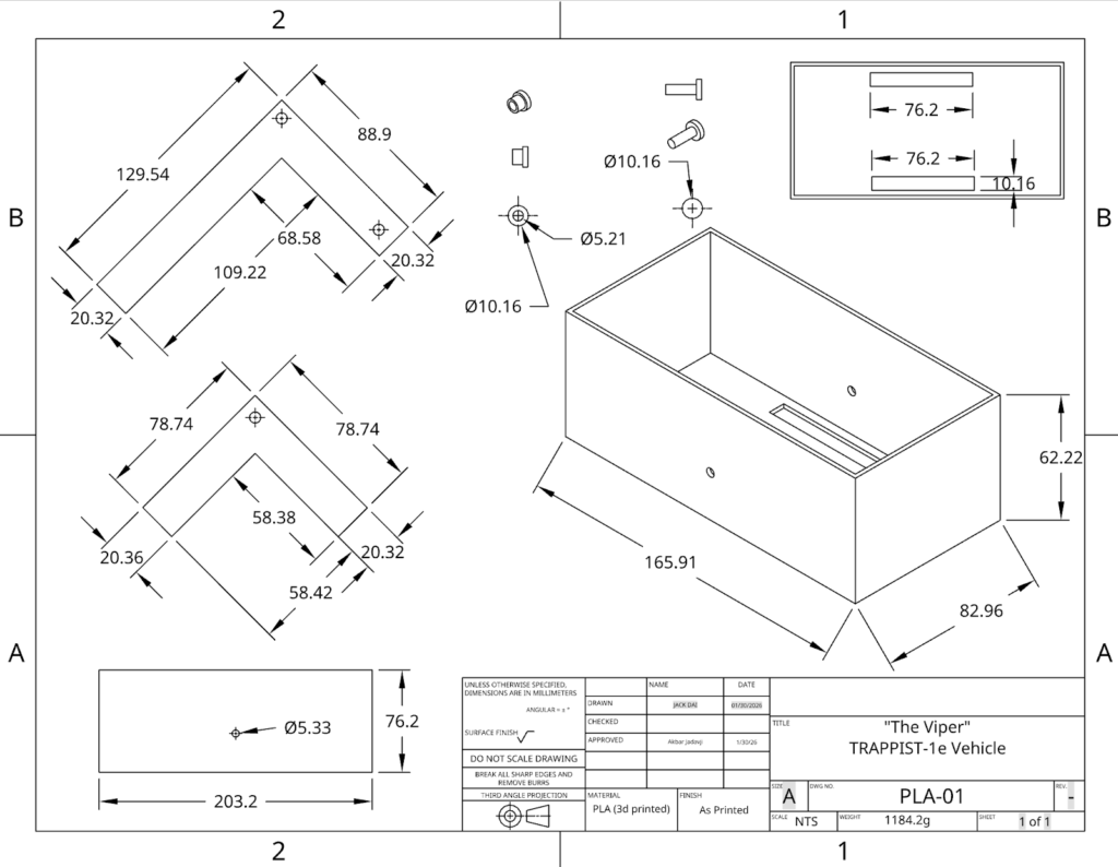
This is what our final product looked like with only one of the rocker-bogie parts on. Normally there is one on both sides. There are four main parts to this:
- The Rocker
- The Bogie
- The Body
- The Screws
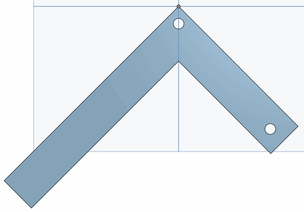
The Rocker is the larger piece and it connects to the body with a central pivot point to allow the vehicle to rotate up and down over the rocks.
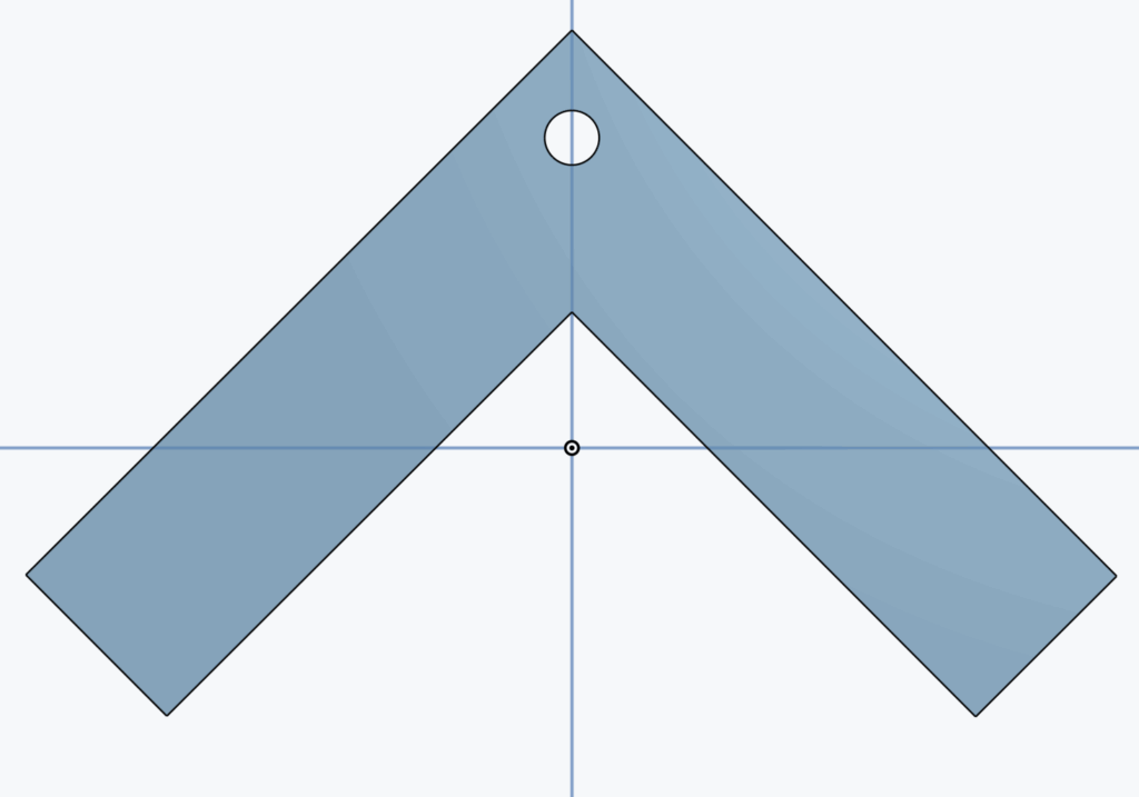
The Bogie arm is the smaller part of the mechanism and it is connected by the hole on the top to the Rocker arm. It stays in the rear and its job is to keep the wheels in contact with the ground as much as possible to maintain consistent movement.
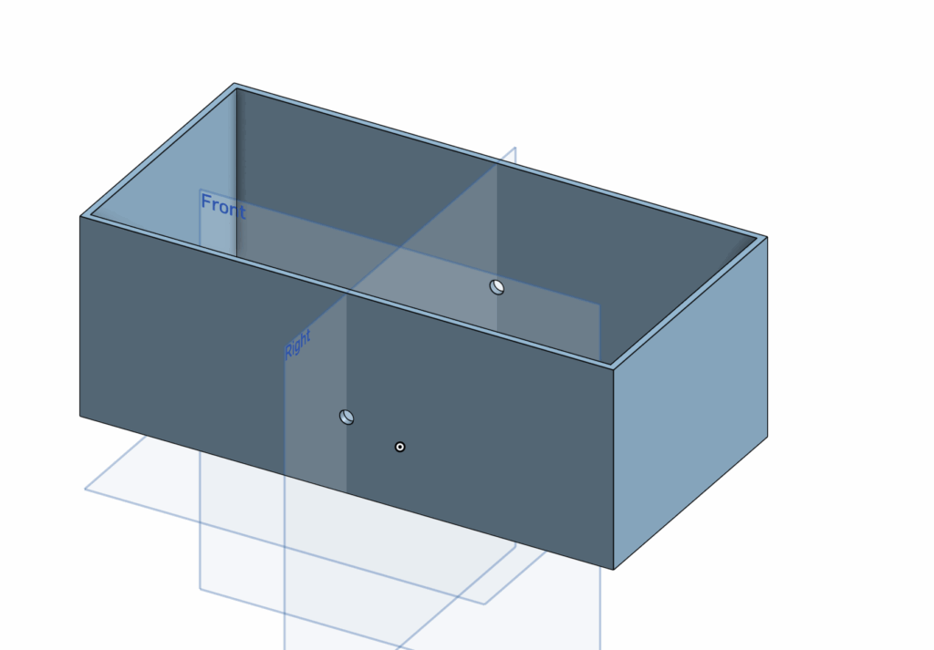
The body is made with two holes that, if you look straight at the vehicle from the side, you will see is right in the middle. This is because we want the body to stay stabilized upwards and by keeping the hole high up and in the middle, it keeps the people inside safe, while the Rocker-Bogie suspension still does all the work.
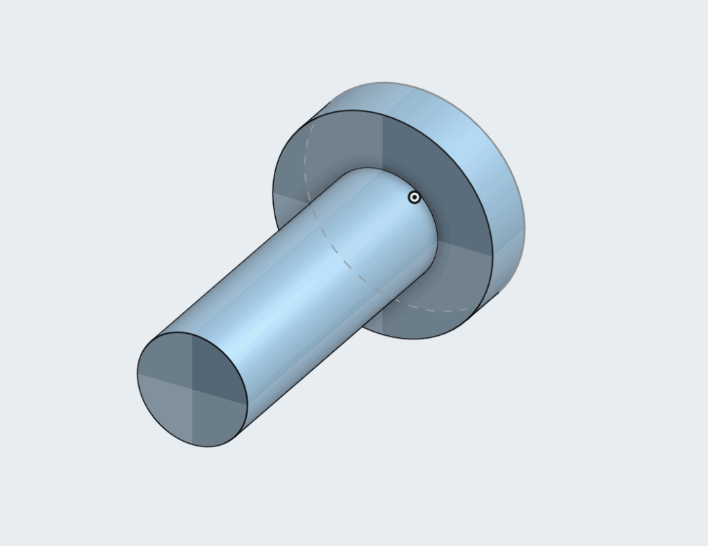
The screws were made specially to fit exactly into our holes we made in the body and the arms. We used custom screws to make sure the arms wouldn’t have difficulty rotating.
However, while we were making all these parts for the CAD, we went through many iterations and failures. We spent a long time thinking about measurements and lengths of the arms. Using Onshape was a process of trial and error because we still didn’t fully understand everything, especially assembly at the end.
We made a diagram for the circuitry to make sure building everything would be as fast as possible as soon as the materials came.
We made an official circuit diagram to show connectivity between each component.
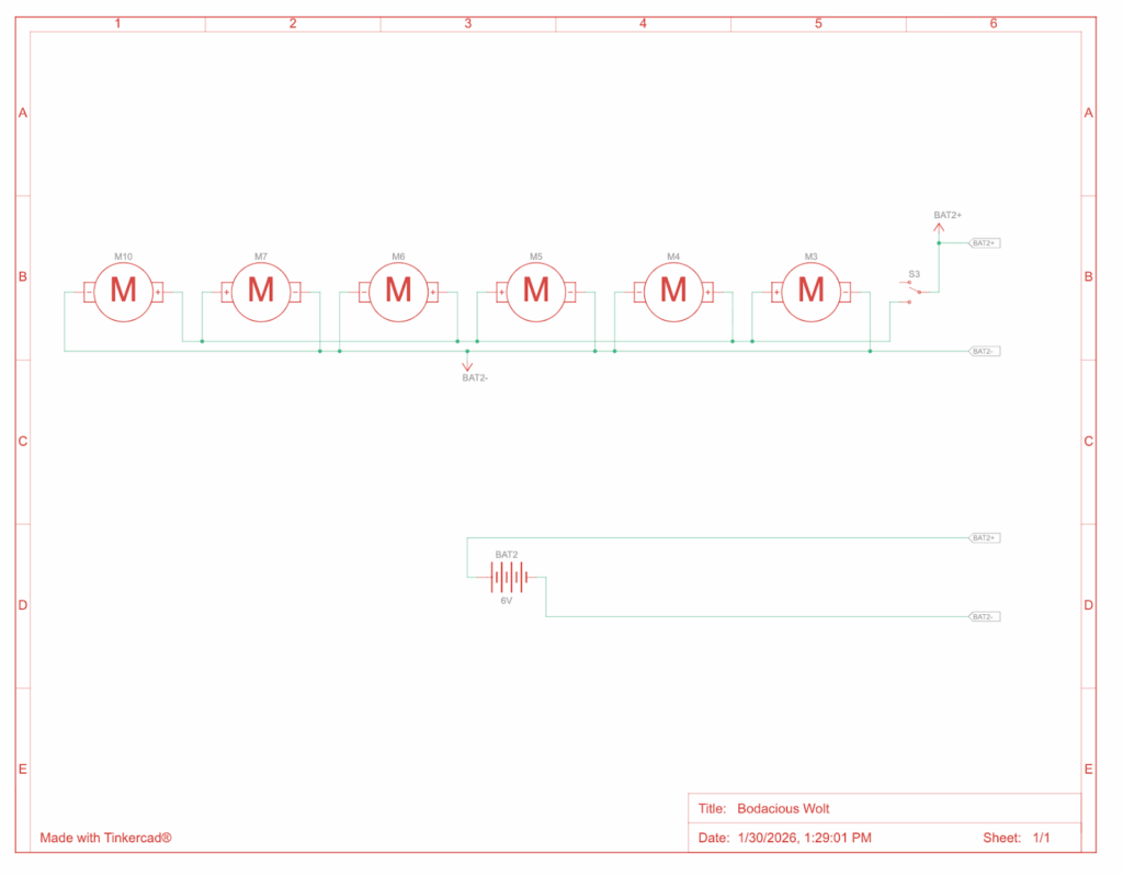
We also purchased 6 motors and 6 wheels to let the vehicle actually move, and glued them onto each end of the arms, 3 on each side. We connected everything with a breadboard attached to some batteries. The process of building everything was very efficient once we had all the parts we needed.
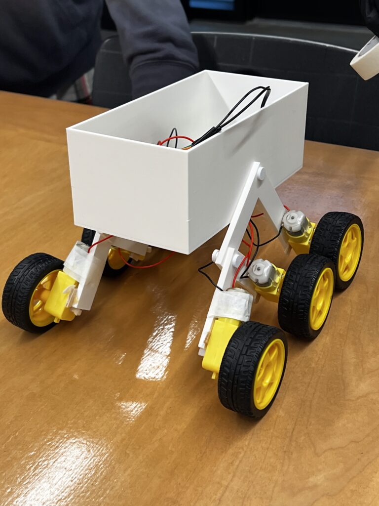
We were very proud to finally have built the car. However, in engineering building the contraption is only half the work. One of the most important parts is testing.
Testing / Data:
The first “test” we ran was immediately after we had built the vehicle. We were happy to see it drive well on flat ground. It drove pretty straight and at a consistent speed.
Next we decided to test it on bumpy terrain by putting some thick pieces of styrofoam on the floor and let it drive through them. We noticed that it had trouble doing this because the distance between the wheels wasn’t big enough for it to fully go over with the Rocker-Bogie mechanism. We learnt that it had a limit, it could go over smaller bumps, but it had difficulty with big ones.
Once we were satisfied that our vehicle could drive, we began the real testing.
Test #1: Rocky Surface
Our first test we planned to do over gravel in order to mimic the terrain that TRAPPIST-1e would have. The goal of the test was to see how efficient the vehicle was on an uneven surface. We used a multimeter to measure voltage before and after and current during the test. We also measured the distance travelled and the time it took.
Table 1: Data from Test #1
| Temp. | V Bef. | V Aft. | Dist. | Mass | Amp | Avg. Amp | Time |
| 3˚C | 6.1V | 5.84V | 2.692m | 1.184kg | 2s: 2.15 4s: 2.05 6s: 2.03 8s: 2.04 10s: 2.02 | 2.058a | 11.5s |
View Test Here: https://youtube.com/shorts/_jUn16Gqg1o
The vehicle did well on the test and travelled on the gravel as we had wanted it to go. We had also collected all the data we needed and were happy with how we ran it.
Test #2: Smooth Surface
We wanted to see how the car would do on a flat surface to compare it to the run on gravel. This is important to determine the efficiency of the suspension we made. We made the test as similar as the previous test, the only difference being the terrain.
Table 2: Data from Test #2
| Temp. | V Bef. | V Aft. | Dist. | Mass | Amp | Avg. Amp | Time |
| 2˚C | 6.03V | 5.92V | 2.692m | 1.184kg | 2s: 1.95 4s: 1.93 6s: 1.95 8s: 1.95 | 1.945a | 8.77s |
View Test Here: https://youtube.com/shorts/xxgDtQGukH4
The vehicle did well on the test and drove in a proper straight line. We were happy with the results from this test because this meant we could calculate comparative efficiency.
Test #3: Test Day
On the final Test Day, our vehicle broke down so we were unable to test. One of the wires for a motor broke and without enough time to solder it together, we had to sit the test out.
However we had already gathered enough data to do a good analysis of our vehicle.
Analysis
The goal of this analysis is to determine the efficiency of the vehicle. Efficiency is defined as useful energy output divided by total energy input. Because of the limitations of our data, we are unable to measure useful energy output. In engineering, another concept is commonly used called traversal efficiency, which is defined as distance in meters the vehicle travelled per Joule of energy used.
The formula for electrical energy is written below.
Where V is average voltage, I is average current, and t is time. We calculated average voltage with the voltage before and after the test. Similarly, average current was calculated with the average of the current at different times during the test.
Test #1:
Test #2:
Results:
Test #1:
Test #2:
Comparative Efficiency
Based on the two tests we did, we can compare them to understand how much the obstacles affected the vehicles ability to drive.
This means that the vehicle was 72% as efficient on gravel compared to smoother terrain.
It is important to note that true efficiency in this case should be mechanical efficiency. In order to calculate this, you calculate the product of force and distance, all divided by energy input. We are unable to calculate it because it requires us to measure friction or torque. Therefore our method for calculating efficiency is much more reliable and would not rely on estimates.
Conclusion / Evaluation:
From this process, we learned how to bring an idea to life. We started small in the brainstorming stage, thinking about little details and piecing together a design prompt. Then we went to the designing stage, going through many designs of how we pictured the vehicle in our heads and putting it on the CAD. After that, we 3D printed it and put everything together. Once we did that, we went on to test the vehicle a few times to understand how good it really was.
We as a group were proud of how we performed. Our vehicle made it through almost all of our tests and had some pretty strong results. One thing that surprised me was the efficiency results. For the gravel test which was meant to simulate the real planet, we got 72% relative traversal efficiency. This is a descent result, it is 28% less efficient on uneven surfaces, showing the effect of rocky terrain.
Had we the opportunity to improve our design, first of all we would redo the CAD to increase the distance between the wheels. We learned about this issue on our second unofficial “test” where we tried driving the vehicle over thick pieces of styrofoam. The wheels would get caught against each other as it tried to drive over.
However, I think the design was still well made and I think it would work on our planet, TRAPPIST-1e. Although it is too far for us to see exactly what the terrain looks like, based on the predictions of the terrain, it is rocky and uneven. This is precisely what our vehicle is made for, which is why I think it would perform well.
To summarize the design prompt, we need to build a vehicle to survive TRAPPIST-1e’s dangerous conditions and carry 4 passengers over a distance of 10km. Our design has the potential to do all of this. It will, of course, need some larger tweaks as we scale the vehicle, but the general design our group made would perform on our planet.
AI Transcript
https://docs.google.com/document/d/1tC3UnxzQEu-qb37PGq7NCgX6LMTtaMW_HYrejN_4fNE/edit?tab=t.0
https://docs.google.com/document/d/1Zt_zXJmNXqmctTyyoRrMyf3LQKth9ItZO-eXazM3d9Q/edit?tab=t.0
Leave a Reply to akbarj Cancel reply