Project Goals
What problem did you set out to solve?
Every day, some people wake up unable to feel anything but their head. To eat breakfast, they are fed by a caretaker because their hands are paralyzed. Around 15.4 million people deal with Spinal Cord Injuries(SCIs) in the world. This is such a significant problem because paraplegic and tetraplegic people have much worse quality of their lives. They have to deal with all their daily activities without being able to move so much of their body. Paraplegics can’t move their legs and tetraplegics can’t move their arms or legs, making them almost immobile.
That is a very large problem. To narrow the scope, I decided to prove that the brain’s signals are still there even if they are not able to send anything down to the lower parts of the body. If we can prove they are still present in the body, then later on the technology to artificially move those body parts can be made. Rather than replicating expensive BCI systems, this project looks at: What signals does that body still produce and how can it be used?
Project Constraints
Who are your users?
Because this is such a simple scope of the project, I think the primary user is myself in order to understand the field better. This project could be used by bored patients who wanted to play Flappy Bird, however, it is not at a level to improve their quality of life in any real way.
Eventually when this projects gets to a usable level, I will be catering to SCI patients. Typically, these are males with an average age of injury of 43 years old. According to a study on BCIs after SCI, a survey was done on veterans with SCI, and they all wanted restoration of bladder and bowel control, walking, and arm/hand functionality. Overall, they just wanted independent operation. Although BCI systems for rehabilitation already exist, they face two major problems. The first is that they are still in the experimental phase and are not ready for clinical application. The second is that non-invasive options struggle with consistent signals and are bulky and uncomfortable. This gap is where my project will fit in – a non-invasive option that is convenient to those users.
What is the time frame of the project?
The project ran from early February to early May, making it about 3 months.
What other constraints have you identified?
One of the biggest constraints for me for this project was hardware. First of all, all headsets that would work for this kind of project were very expensive. In terms of budget, we ended up spending $350 CAD on the headset and an additional $15 for access to the platform – MindMonitor – that streamed the headset’s signals wirelessly to my laptop. This headset – the Muse 2 – was one of the cheapest I could find to work with this kind of project. I also had to deal with the problem that the electrodes were not placed on the motor cortex, the part of the brain associated with movement. On top of that, I had never done any projects in this field – one more reason why it was such a simple project – and this constraint made me have to learn how to deal with coding in this environment.
Project Expectations
What is the scope of your problem?
When I was making the project, I knew it should focus on reading the brain signals from the Muse 2 and use them for something. I did not intend to work with actual SCI patients or make a medical device because I knew I was still learning how the field works.
How will you identify or define success?
If I could get an input from the brain and use it, I would call that success.
Design Choices
What is your solution?
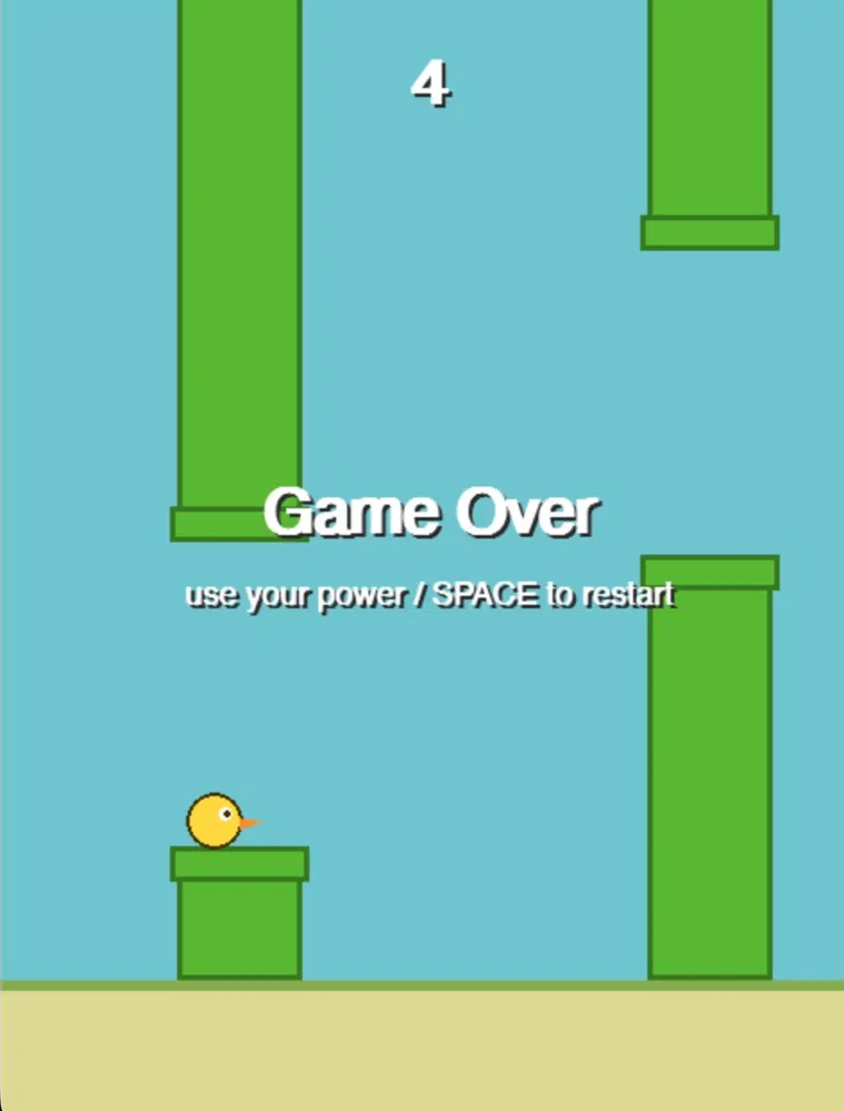
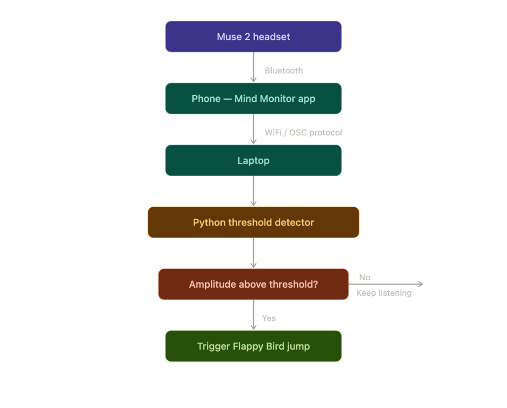
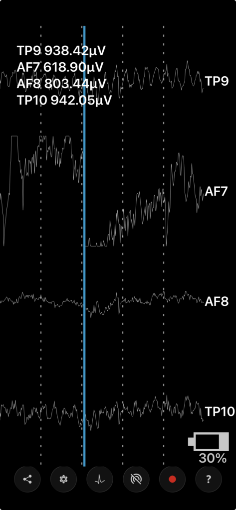
I built a system for people to play Flappy Bird with their mind. The framework starts with a Muse 2 headset that receives signals from the TP9, TP10, AF7, and AF8 electrodes. Those signals are sent to my phone using Bluetooth, then streamed to my laptop using the Mind Monitor app. Once the signals are on the computer, the code would watch for the signal’s amplitude to pass a certain threshold, causing a jump in the Flappy Bird game. Every time the user triggered a spike, the bird jumped.
All of these choices were intentional decisions. The Muse 2 was one of the cheapest headsets that was in line with what I was trying to do. Because I decided on the Muse 2, I used Mind Monitor because their app is built for the Muse ecosystem. A simple amplitude threshold detector was used over a more complex algorithm because for this use case, that’s all that is required. All the game needs is when it should jump and when it shouldn’t, and a complex classifier would just be unneeded complexity. Flappy Bird was used because it is just a binary jump or no jump that fits perfectly with the vision.
What does it look like?
Project Planning
What are the steps to get to your goal?
First, I started with making sure the framework worked. I wanted to see if the signals could go from the headset to my computer. I made a file that I later built off of to receive the streaming data and just log it onto my computer. Once that was successful, I used that data to make a threshold reader that would trigger every time the signal passed the threshold. I then made the game with the help of Claude Code. I decided to use Claude Code because I saw the game as a way to test my project rather than the actual project itself.
What feedback have you received? From where? How has your design evolved?
I didn’t receive much feedback on my project because I only showcased it at the project presentations and no sooner. Looking back, I think this is a mistake because some feedback might have helped me evolve my design.
Bill of Materials and Cost Analysis
| Muse 2 Headset | $350 |
| Mind Monitor app | $15 |
| Python and Libraries | Free |
| Claude Code | Free access |
| Total | $365 |
$365 seems like a very high price for what I ended up building. The reason is that BCIs are such a new field, and breaking into it requires a high upfront cost. However, the headset I ended up purchasing is not even very powerful for the types of applications I am interested in, but those headsets go into the thousands.
Testing and Validation
Why do you think that your solution will be successful? What evidence do you have? If you tested the prototype, how did you do this and what did the test look like?
Once I had everything ready, I needed to test it and play the game. I tried different ways of controlling the signal – jaw clenching, eyebrow raising, and blinking – to see which were the most powerful and most consistent. After trying to trigger a jump with those different EMG signals I understood which were better and worse.
| Type | Pros | Cons |
| Clench Jaw | Consistent, strong signal | High effort required |
| Blink | Good signal, low effort | Inconsistent signal |
| Raise Eyebrows | Consistent, good signal, low effort | Looks funny (No real cons) |
All of them worked to play Flappy Bird. I was able to get good scores with all of these methods.
Although these signals are not actually EEG signals, they would still be useful in helping someone with a SCI. They are either paralyzed below the neck or below the torso, but their face is still able to move in both cases. Knowing when a blink, a clench, or an eyebrow raise is performed could lead to a simple control mechanism for an SCI patient. Even though direct mind control seems ideal, it is hard to train someone who hasn’t engaged their motor cortex in so long to imagine movements like jumping. For this reason, we can use actions they are already familiar with to allow them to use technology that will improve their quality of life.
Sustainability / Code of Ethics
What ethical implications exist in your problem, solution, and process?
Patients with SCIs are very vulnerable with their conditions, and if they are in a situation where they depend on BCI technology that fails, they will be greatly affected. That failure may cause serious problems in their lives and they will probably need to be back in a hospital relying on the old hospital workers they used to have.
In terms of privacy, although my specific project doesn’t present any serious concerns, this technology could be taken advantage of in the future by interpreting the raw data from the brain. The level of damage this could cause depends on the sophistication of the headset and of the interpretation algorithm.
Conclusions and Recommendations
I think that I succeeded because I was able to use an input that came from the brain to do something – jump in Flappy Bird. This matters because now I’ve worked with BCIs and this opens many doors for later on. In the future, I hope to continue my work with BCIs. I hope to get access to a more powerful one so that I can build impactful projects. If someone wanted to continue this work, they should focus on getting access to better hardware. As I worked on this project, I noticed that the limitations of this headset limited what I was able to build. I think that if I had a more powerful headset with electrodes on the motor cortex, I would’ve been able to build a more complex and useful project.
References
World Health Organization. (2024, April 16). Spinal cord injury. https://www.who.int/news-room/fact-sheets/detail/spinal-cord-injury
Collinger, J. L., Boninger, M. L., Bruns, T. M., Curley, K., Wang, W., & Weber, D. J. (2013). Functional priorities, assistive technology, and brain-computer interfaces after spinal cord injury. Journal of Rehabilitation Research and Development, 50(2), 145–160. https://www.ncbi.nlm.nih.gov/pmc/articles/PMC3684986/
Jiang, L., Li, F., Tang, Y., & Liu, X. (2023). Brain–computer interface: trend, challenges, and threats. Frontiers in Computational Neuroscience. https://pmc.ncbi.nlm.nih.gov/articles/PMC10403483/
Appendices
Appendix A — Final Project Code
oscreceiver.py
from pythonosc import dispatcher, osc_server
import argparse
import time

PORT = 5000


def handle_eeg(address, *args):
    labels = ["TP9", "AF7", "AF8", "TP10", "AUX"]
    values = "  ".join(f"{l}={v:+8.2f}" for l, v in zip(labels, args))
    print(f"[EEG] {values}")


def handle_any(address, *args):
    print(f"[OSC] {address}  {list(args)}")


def main():
    parser = argparse.ArgumentParser(description="Muse 2 OSC receiver")
    parser.add_argument("--port", type=int, default=PORT)
    parser.add_argument("--eeg-only", action="store_true",
                        help="Print only /muse/eeg messages")
    args = parser.parse_args()

    d = dispatcher.Dispatcher()
    d.map("/muse/eeg", handle_eeg)
    if not args.eeg_only:
        d.set_default_handler(handle_any)

    server = osc_server.ThreadingOSCUDPServer(("0.0.0.0", args.port), d)
    print(f"Listening for OSC on UDP port {args.port} …  (Ctrl-C to stop)")
    print("Expected channel order: TP9  AF7  AF8  TP10  AUX\n")
    try:
        server.serve_forever()
    except KeyboardInterrupt:
        print("\nStopped.")


if __name__ == "__main__":
    main()
jaw_detector.py
from pythonosc import dispatcher, osc_server
from collections import deque
import argparse
import math
import time

SAMPLE_RATE_HZ = 256
DEFAULT_WINDOW_SEC = 0.25
DEFAULT_THRESHOLD_UV = 150.0
DEFAULT_DEBOUNCE_SEC = 0.35


class JawClenchDetector:
    def __init__(
        self,
        threshold_uv: float = DEFAULT_THRESHOLD_UV,
        window_sec: float = DEFAULT_WINDOW_SEC,
        debounce_sec: float = DEFAULT_DEBOUNCE_SEC,
        on_clench=None,
    ):
        self.threshold = threshold_uv
        self.debounce = debounce_sec
        self.on_clench = on_clench
        window_samples = max(1, int(window_sec * SAMPLE_RATE_HZ))
        self.tp9 = deque(maxlen=window_samples)
        self.tp10 = deque(maxlen=window_samples)
        self.last_fire_time = 0.0
        self.last_amplitude = 0.0

    def feed(self, tp9: float, tp10: float):
        self.tp9.append(tp9)
        self.tp10.append(tp10)
        if len(self.tp9) < self.tp9.maxlen:
            return

        n = len(self.tp9)
        mean9 = sum(self.tp9) / n
        mean10 = sum(self.tp10) / n
        var9 = sum((v - mean9) ** 2 for v in self.tp9) / n
        var10 = sum((v - mean10) ** 2 for v in self.tp10) / n
        amp = (math.sqrt(var9) + math.sqrt(var10)) / 2.0
        self.last_amplitude = amp

        if amp >= self.threshold:
            now = time.monotonic()
            if now - self.last_fire_time >= self.debounce:
                self.last_fire_time = now
                if self.on_clench:
                    self.on_clench(amp)


def _bar(value: float, max_value: float, width: int = 40) -> str:
    filled = min(width, int(width * value / max_value))
    return "█" * filled + "·" * (width - filled)


def _run_standalone(port: int, threshold: float):
    detector = JawClenchDetector(
        threshold_uv=threshold,
        on_clench=lambda amp: print(f"\n*** CLENCH ({amp:6.1f} µV) ***"),
    )

    def handle_eeg(address, *args):
        if len(args) < 4:
            return
        tp9, _af7, _af8, tp10 = args[0], args[1], args[2], args[3]
        detector.feed(tp9, tp10)

    d = dispatcher.Dispatcher()
    d.map("/muse/eeg", handle_eeg)
    server = osc_server.ThreadingOSCUDPServer(("0.0.0.0", port), d)

    import threading
    t = threading.Thread(target=server.serve_forever, daemon=True)
    t.start()

    print(f"Listening on UDP {port}.  Threshold: {threshold:.0f} µV.")
    print("Live amplitude (TP9+TP10 RMS) — clench your jaw to test:\n")
    bar_max = max(threshold * 2.5, 200.0)
    try:
        while True:
            amp = detector.last_amplitude
            marker = "  <-- TRIGGER" if amp >= threshold else ""
            print(f"\r{_bar(amp, bar_max)} {amp:7.1f} µV{marker}   ", end="", flush=True)
            time.sleep(0.05)
    except KeyboardInterrupt:
        print("\nStopped.")


def main():
    parser = argparse.ArgumentParser(description="Muse jaw clench detector")
    parser.add_argument("--port", type=int, default=5000)
    parser.add_argument("--threshold", type=float, default=DEFAULT_THRESHOLD_UV)
    args = parser.parse_args()
    _run_standalone(args.port, args.threshold)


if __name__ == "__main__":
    main()
jump_detector.py
from collections import deque
from pythonosc import dispatcher, osc_server
import argparse
import math
import threading
import time

ACC_RATE_HZ = 52
DEFAULT_FREEFALL_G = 0.5
DEFAULT_GROUNDED_G = 0.85
DEFAULT_DEBOUNCE_SEC = 0.8


class JumpDetector:
    def __init__(
        self,
        freefall_g: float = DEFAULT_FREEFALL_G,
        grounded_g: float = DEFAULT_GROUNDED_G,
        debounce_sec: float = DEFAULT_DEBOUNCE_SEC,
        on_jump=None,
    ):
        self.freefall_g = freefall_g
        self.grounded_g = grounded_g
        self.debounce = debounce_sec
        self.on_jump = on_jump
        self.last_magnitude = 0.0
        self.last_fire = 0.0
        self._airborne = False

    def feed(self, x: float, y: float, z: float):
        mag = math.sqrt(x * x + y * y + z * z)
        self.last_magnitude = mag

        if not self._airborne:
            if mag < self.freefall_g:
                now = time.monotonic()
                if now - self.last_fire >= self.debounce:
                    self._airborne = True
                    self.last_fire = now
                    if self.on_jump:
                        self.on_jump(mag)
        else:
            if mag > self.grounded_g:
                self._airborne = False


def _bar(value, max_value, width=40):
    filled = min(width, int(width * value / max_value))
    return "█" * filled + "·" * (width - filled)


def _run_standalone(port, freefall):
    detector = JumpDetector(
        freefall_g=freefall,
        on_jump=lambda mag: print(f"\n*** JUMP (freefall {mag:.2f} g) ***"),
    )

    def handle_acc(address, *args):
        if len(args) >= 3:
            detector.feed(args[0], args[1], args[2])

    d = dispatcher.Dispatcher()
    d.map("/muse/acc", handle_acc)
    server = osc_server.ThreadingOSCUDPServer(("0.0.0.0", port), d)
    t = threading.Thread(target=server.serve_forever, daemon=True)
    t.start()

    print(f"Listening on UDP {port}.  Freefall trigger: < {freefall:.2f} g")
    try:
        while True:
            mag = detector.last_magnitude
            state = "AIRBORNE" if detector._airborne else "grounded"
            marker = "  <-- FREEFALL" if mag < freefall else ""
            print(f"\r{_bar(mag, 4.0)} {mag:.3f} g  [{state}]{marker}   ",
                  end="", flush=True)
            time.sleep(0.05)
    except KeyboardInterrupt:
        print("\nStopped.")


def main():
    parser = argparse.ArgumentParser(description="Muse jump detector")
    parser.add_argument("--port", type=int, default=5000)
    parser.add_argument("--freefall", type=float, default=DEFAULT_FREEFALL_G)
    args = parser.parse_args()
    _run_standalone(args.port, args.freefall)


if __name__ == "__main__":
    main()
bci_flappy.py
import argparse
import threading

import pygame
from pythonosc import dispatcher, osc_server

from flappy import Game
from jaw_detector import JawClenchDetector
from jump_detector import JumpDetector

CLENCH_EVENT = pygame.USEREVENT + 1
JUMP_EVENT   = pygame.USEREVENT + 2


def start_osc_listener(port, clench_threshold, jump_threshold):
    def on_clench(amp):
        pygame.event.post(pygame.event.Event(CLENCH_EVENT, value=amp))

    def on_jump(mag):
        pygame.event.post(pygame.event.Event(JUMP_EVENT, value=mag))

    clench_det = JawClenchDetector(threshold_uv=clench_threshold, on_clench=on_clench)
    jump_det   = JumpDetector(freefall_g=jump_threshold, on_jump=on_jump)

    def handle_eeg(_addr, *args):
        if len(args) >= 4:
            clench_det.feed(args[0], args[3])

    def handle_acc(_addr, *args):
        if len(args) >= 3:
            jump_det.feed(args[0], args[1], args[2])

    d = dispatcher.Dispatcher()
    d.map("/muse/eeg", handle_eeg)
    d.map("/muse/acc", handle_acc)

    server = osc_server.ThreadingOSCUDPServer(("0.0.0.0", port), d)
    threading.Thread(target=server.serve_forever, daemon=True).start()

    print(f"OSC listening on UDP {port}")
    print(f"  Jaw clench threshold : {clench_threshold:.0f} µV")
    print(f"  Jump threshold       : {jump_threshold:.2f} g")
    print(f"  SPACE / click also work as fallback\n")


def main():
    parser = argparse.ArgumentParser(description="BCI Flappy Bird")
    parser.add_argument("--port",              type=int,   default=5000)
    parser.add_argument("--clench-threshold",  type=float, default=45.0,
                        help="Jaw clench RMS µV threshold")
    parser.add_argument("--jump-threshold",    type=float, default=1.8,
                        help="Jump acceleration magnitude in g")
    args = parser.parse_args()

    game = Game()
    start_osc_listener(args.port, args.clench_threshold, args.jump_threshold)

    running = True
    while running:
        dt = game.clock.tick(60) / 1000.0
        for e in pygame.event.get():
            if e.type == CLENCH_EVENT:
                print(f"  jaw  {e.value:6.1f} µV -> flap")
                game.jump()
            elif e.type == JUMP_EVENT:
                print(f"  jump {e.value:.2f} g  -> flap")
                game.jump()
            elif not game.handle_event(e):
                running = False
        game.update(dt)
        game.draw()
    pygame.quit()


if __name__ == "__main__":
    main()
Appendix B –
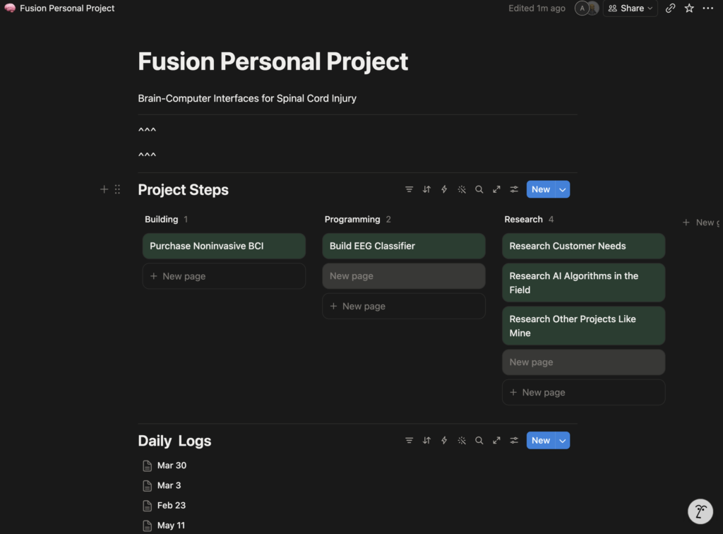
A Kanban board was used to organize the project’s tasks. Daily logs were used to keep track of progress.