INTRO
In this project, the problem we set out to solve was to design a vehicle that would allow 4 human astronauts to travel on an exoplanet known as Teegarden’s Star B. Our definition statement was: “Four human astronauts need a safe and efficient way to travel 10 continuous km across Teegarden’s Star b due to unique atmospheric, gravitational, and geological conditions. We must overcome challenges such as a differing gravitational pull, rocky terrain, and uncertain atmosphere by creating a testing environment that models these conditions.”
This test plays a very important role in our project because it allows us to determine whether the vehicle will actually solve the problem we set out to solve. For our experiment, we used kinetic sand to build up mountains, which represent the rocky terrain of Teegarden’s star B. We also used paper balls to represent boulders.
Method / Procedure
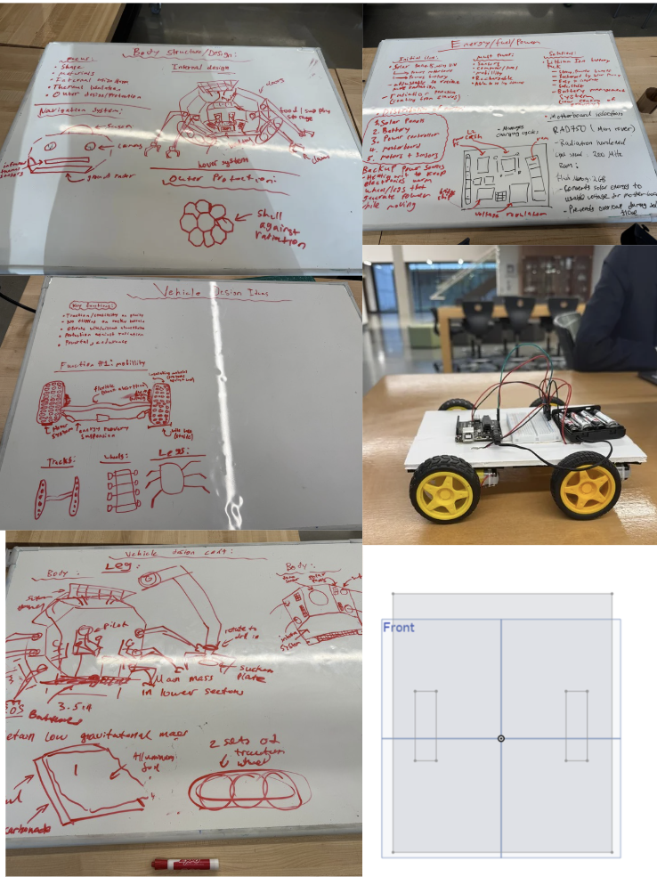
This is a collection of our brainstorming ideas to design our vehicle. The vehicle you see on the right was our prototype, and the image below is the board design we made for our vehicle.
This vehicle was made to address the three major difficulties we identified to travel on Teegarden’s star B: 1. uneven rocky terrain, 2. gravitational condition, 3. UV rays. Unfortunatelly due to the limitations of our classroom testing enviorment, we were really only able to test one of them, which was the uneven rocky terrain, which I shared how we built it earlier.
PROTOTYPING
Prototype 1
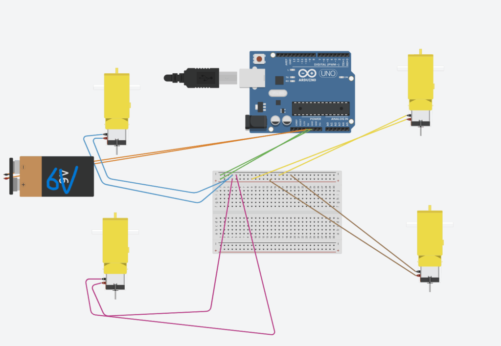
(Our circuit)
At the start, we began building our prototype by first cutting out a base, which, at the time, was just a foam board that was measured out with a ruler. When we had our base, we then went on to attach an Arduino Uno and a breadboard to the base. Then, we put together 4 sets of wheels, each one with a motor attached to it, and assembled them on the four corners of the base.
Then, we put 4 AA batteries into a battery holder and connected that to the Arduino Uno, effectively powering the entire vehicle. The last step was to correctly wire the motors to the power source, and we did that by taking 2 male-male wires and attaching them from the 5V and the GND of the Arduino to the VCC power rail and the GND power rail.
Prototype 2
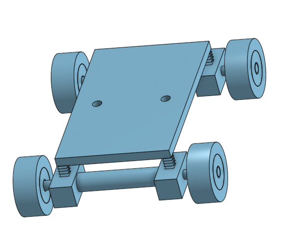
(Intended design)
In preparation for the next test, we decided to switch out our foam board with a wooden board because we thought it would be more stable and could hold more weight, as we wanted to attach the battery pack to the vehicle and make the vehicle controllable by Bluetooth.
As a result of this, we took apart a vehicle, cut out a new wooden base, and still just measured with a ruler. A big goal for our test 2 vehicle was for it to actually be able to climb up something, and to do that, we thought the best solution was to add suspension to our vehicle. And ontop of that, we decided to design a suspension linkage that we thought would also help the car climb.
FAILURES / MISTAKES
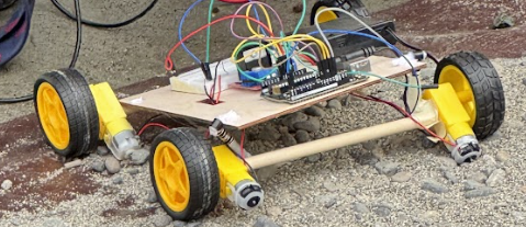
I think an overarching mistake we made during this entire project was overcomplicating things and underestimating the difficulty it would be to make all the things we wanted to do come to life. An example of this is trying to add suspension. As mentioned earlier, we wanted to add suspension to our vehicle to help it climb. However, we severely underestimated the difficulty of adding them, which resulted in this make-shift suspension you see here. Not only did this not help our vehicle climb, but it also made the overall structure very weak.
A second mistake we made was not testing our vehicle as we went. After taking appart of first protype we never actually tested if the vehicle would work. This was partially because we didn’t really have the chance to do so, because we tried to make it bluetooth controllabe, which made the car unmovable even if we plugged the battery in. Furthermore, we thought that we hadn’t changed many things in the circuit, and it still functioned the same way, so we assumed there would be no reason for it to malfunction.
Going deeper into a mistake I mentioned, making our vehicle blue-tooth controlablem, this would prove to be one of the biggest mistakes we made, as when test day arrived, we still had not figured out how to connect the HC-05 Bluetooth module to an actual Bluetooth control. Thus, we had no choice but to scrap that idea and instead try to just plug in the motor wires straight into the breadboard. I will talk more about this later.
Testing
During the second test, our vehicle did not perform as we had expected it to. The vehicle would not move, and the test was basically just a flop. Several factors may have caused this failure, the first being not enough power. Using four motors requires a lot of current for all 4 motors to function properly, and the 4 AA batteries might just now have been enough. This was also shown during our data collection of the voltage, where we got fluctuation between 0.7 V and 0.9 V. This could indicate that the electrical system was struggling to consistently supply enough current to the motors. A second issue that could have affected the results was the wiring.
Because we wanted to make the vehicle Bluetooth-controllable, we had to cut off the male pins. This left only the copper wires, which would have been sufficient if we were using the DC motor driver. However, as mentioned earlier, we couldn’t figure out how to connect the HC-05 Bluetooth module to an actual control system. This forced us to attempt connecting the wires directly to the breadboard, similar to what we did during the first test. Unfortunately, this time the copper wires were extremely thin and flexible, and most couldn’t reach deep enough into the breadboard. The main issue with this approach was that not all the wires may have been fully connected or receiving current from the breadboard, likely causing the test to fail.
Data
Trying to get Data from our tests proved to be very difficult. This is because the battery pack hid all the wires, which meant we weren’t able to get the output of electricity.
Furthermore, because of the way our circuit worked
Battery pack -> Arduino -> Breadboard -> Motors
There was no way of getting the current because our circuit does not go back to the battery, making it an open circuit. Because it’s an open circuit, it is impossible to calculate energy efficiency as no current flows, and energy efficiency is not really meaningful here, as it only makes sense when energy is actually being transferred.
Analysis
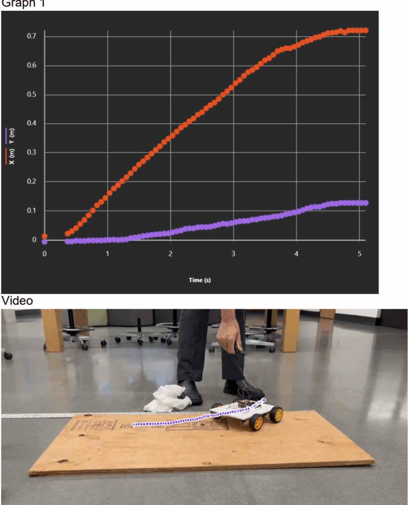
VIDEOS + GRAPH + VIDEO ANLYSIS
ATTEMPTED CALCULATION(hypothetical)
(I’m going to try to calculate an energy efficiency of some sort
In this scenario, the circuit is closed, and there is actually current flowing through the system.)
During the test, the voltage fluctuated between 0.6V and 0.9V. This tells us that the battery system was unable to supply a stable power to the motors.
Current Calculation
Using Ohm’s law and the formula below, we can get the current
We know the voltage of our circuit, which is situated between 0.6 V and 0.9V. We are going to use the average of that, which is 0.75 V. The internal Resistance of the 4 used Alkaline AA batteries is approximately 0.8Ω. By using a resistor of 10Ω, it would give us a total resistance of: 10.8Ω
To find the current, we can use the formula that we stated before. Here, Vbattery represents the voltage of the battery without any load (resistance), which is 6V, as each alkaline AA battery supplies 1.3 V (because they are not new), and we are using 4 of them. Current is: 0.418 A (repeating)
The input power of our circuit is the battery, and to calculate that, we can use the formula:
Where P is the power, V is the voltage, and I is the current.
So our equation to calculate the power input (Pin) of our battery would be:
Using the same equation, we can find the power output (Pout) of our motors, which would be:
We now have both the hypothetical Power input and output of our circuit. Using the energy efficiency forumula we are now able to find the hypothetical energy efficiency of our circuit. The formula for energy efficiency is:
Our calculation would be
In conclusion, the hypothetical energy efficiency of our circuit, if it were a closed circuit and current remained the exact same throughout the system, would have an energy efficiency of 12%, meaning it lost 88% of its energy.
EXPLANATION
As I’ve said before, we can’t calculate any meaningful energy efficiency. Although we attempted to calculate the energy efficiency of the system, a reliable efficiency value cannot be determined. Energy efficiency requires accurate values for both input power from the battery and useful output power delivered to the motors under load.
However, some data that we can analyze is the voltage. In this system, the circuit voltage dropped significantly from the battery’s normal 6V to around 0.6V – 0.9V when the motors were connected. This shows us that there was an extremely large energy loss somewhere, which could be due to the internal resistance of the motors
Because of these limitations, any calculated energy efficiency would most likely be inaccurate. However, the voltage drop clearly demonstrates that a significant portion of the battery’s energy was taken away by the internal resistance rather than converted into useful work by the motors.
The results here can be carried forward when preparing for our hypothetical new home on Teegarden Star B and could help us improve our new home. These results highlight the importance of energy efficiency. Just like in the vehicle, not all energy input is transferred to energy output, and we didn’t have enough energy to power our vehicle. So it’s better to be able to transfer more energy than required.
Conclusion/Evaluation
In conclusion, during this project, we tried to build a vehicle that would fulfill our definition statement. However, looking at the test results, I don’t think the vehicle as it is right now would function well on Teegarden’s Star B. However, from these experiments, we have learned a lot about how to improve our vehicle so that, hypothetically, if we were to go to Teegarden’s Star B, it would function. And the first implication that has to be made would be to increase the amount of energy input we get. It was proven in our experiment that we clearly did not have enough, and if we were to actually build this vehicle life-size, it would not function. A second implication that should be made is adding a way for the vehicle to climb. Teegarden’s star B has a very rocky terrain and requires our vehicle to be able to scale that terrain. Implications such as bigger tires, better tractions, more RPM, and a suspension are all ways to help the vehicle climb. Finally, the last implication that should be made is that the vehicle should be controllable. While we tried to implement this onto our protype but, we were unable to do so. Although this isn’t a big problem on a smaller testing scale, it will be crucial to be able to control the vehicle on Teegarden’s star B. Otherwise, if the vehicle was uncontrollable and could only go in a straight line, it could run into many problems like trying to cross a valley, or going around a mountain, or avoiding a boulder, etc.
Leave a Reply to Ms. Holmen Cancel reply