Intro / Abstract:
- My group (Michael, Dean and I), had a goal of designing a vehicle that would transport 4 astronauts on a potentially habitable planet or moon. Callisto is a moon, and we chose it as the most habitable because of its unique characteristic: a subsurface ocean. This indicates potential for life, likely marine life in that ocean, or at least potential for future development. Also, it is safe from radiation – something we take as granted, but the truth is that the majority of planets and moons are affected by radiation levels so great that they make human life impossible. Callisto is the third largest moon in the Solar System and therefore has potential space to accommodate humans.
After considering what is realistically possible to achieve in terms of progress on a vehicle, we came up with the following definition statement:
- The vehicle should be capable of operating independently on a remote, frozen, and airless moon with extreme cold, low gravity, and weak sunlight. It needs to generate power on its own without relying on solar energy, thermal protection is essential to keep engines, batteries, and fuel operational in extreme cold, and travel through rocky, ice covered terrain. Moreover, the vehicle needs to use fuel efficiently, and to accomplish this, it needs to be not too heavy, with a low center of gravity and good mobility.
- The vehicle should be capable of operating independently on a remote, frozen, and airless moon with extreme cold, low gravity, and weak sunlight. It needs to generate power on its own without relying on solar energy, thermal protection is essential to keep engines, batteries, and fuel operational in extreme cold, and travel through rocky, ice covered terrain. Moreover, the vehicle needs to use fuel efficiently, and to accomplish this, it needs to be not too heavy, with a low center of gravity and good mobility.
Our vision of the product (what we plan to build): We planned to build a vehicle with two or 4 tank treads acting like wheels on the side of our rover vehicle. These would have traction to help it climb over those rocky and icy terrains on Callisto. We aimed to give directions to the vehicle through Arduino code and robotics, and power it with batteries strapped to the vehicle itself. This, along with the tank treads would create an efficient, minimalistic design that generates a lot of power and traction to successfully achieve our design goal. Our primary aim through this is for the vehicle to be able to be versatile and drive through various weather and land conditions. Adaptability and versatility are key, when we are dealing with unknowns – especially unknowns as huge as foreign celestial bodies.
How we plan to build it: The approach we decided on to achieve this was to build our planned Onshape design through 3D printing the CAD design. 3D designing the parts of the vehicle would be a lengthy process, but we were confident the outcome would be worth it. I worked on the Arduino to program the vehicle and add the robotics component to it. As a group, we all worked planning the CAD designs, and Michael designed the actual components. Dean would later assemble the parts for the tank tread, while Michael and I would do more robotics oriented building (motors, soldering, etc).
- The planning we did for this project and vehicle included the research phase where we learnt about celestial bodies we could design a vehicle for then shortlisted them. The type of planet or moon we were assigned greatly influenced what our goals would be for the vehicle, and what type of vehicle it would be. For example, some groups chose the path of underwater submarine type vehicles because their planet was largely water. Our place of choice was one of Jupiter’s moons: Callisto. Its characteristics greatly influenced our design because of its rocky terrain and surface with lots of craters. This made a primary requirement of our vehicle vertical ascension and climbing upwards. When we planned our test, this is what we wanted to evaluate in our vehicle. If it could get over an obstacle of some sort, we would be able to measure the progress and success of the vehicle. Throughout the later stages of the project, we learnt that the efficiency metrics of the vehicle were also important. They tell us how much of the energy that is used to power the vehicle is actually converted into useful energy. Factors such as weight can influence this as well. The idea behind measuring efficiency allows us to make sure we are intentional with every component, and that teaches us that if we pursue engineering, environmental concerns and effectiveness are an important part of vehicle design as well.
Method / Procedure:
- Throughout the building and planning process, I kept track of our progress through logging daily progress as we got closer to test day, documented our planning and took photos and recordings of developments in prototyping, Arduino wiring, etc.
We started the project with research on potentially livable celestial bodies, and gathered information. At the end, we were assigned one of our shortlisted moons, Callisto. Callisto is one of Jupiter’s moons, and the third largest in the solar system. It has multiple characteristics that make it a good choice for livability, and multiple challenges as well. The most promising feature is the fact that there is data that suggests there is a subsurface ocean. The aforementioned size of this moon means that it has the capability to accommodate a large portion of the human population. Challenges of habitability on Callisto include freezing temperatures and 10 times more radiation than Earth. Its radiation is still relatively low compared to the other moons of Jupiter, and this is because it is far from Jupiter. More information on Callisto can be found at this link of my other blog https://wp.stgeorges.bc.ca/shayanc/2025/11/16/planetary-exploration-project/
Our design was heavily influenced by Callisto’s rocky and icy terrain. We recognised the value of traction and climbing over obstacles in this terrain, so we prioritised those in a vehicle that we wanted to build. Then the brainstorming stage came, where we came up with ideas and created a definition statement:
“The vehicle should be capable of operating on a frozen and airless moon with extreme cold, low gravity, and weak sunlight. It will need to protect its internal components from the temperature to an extent, and generate power on its own without relying on solar energy. Thermal protection is essential to keep engines, batteries, and fuel operational in extreme cold, and travel through rocky, ice covered terrain. Moreover, the vehicle needs to use fuel efficiently, and to accomplish this, it needs to be but not too heavy, with a low center of gravity and good mobility.”
Also, we knew that there were a lot of things that we would not be able to address in a small vehicle that high school students were capable of creating, so we decided to address the things that we could. We shortlisted the issues we can try to combat, and the main thing we concluded on was: driving through rough terrain with good grip and traction. It needed to be a goal that we could test, and we could test this.
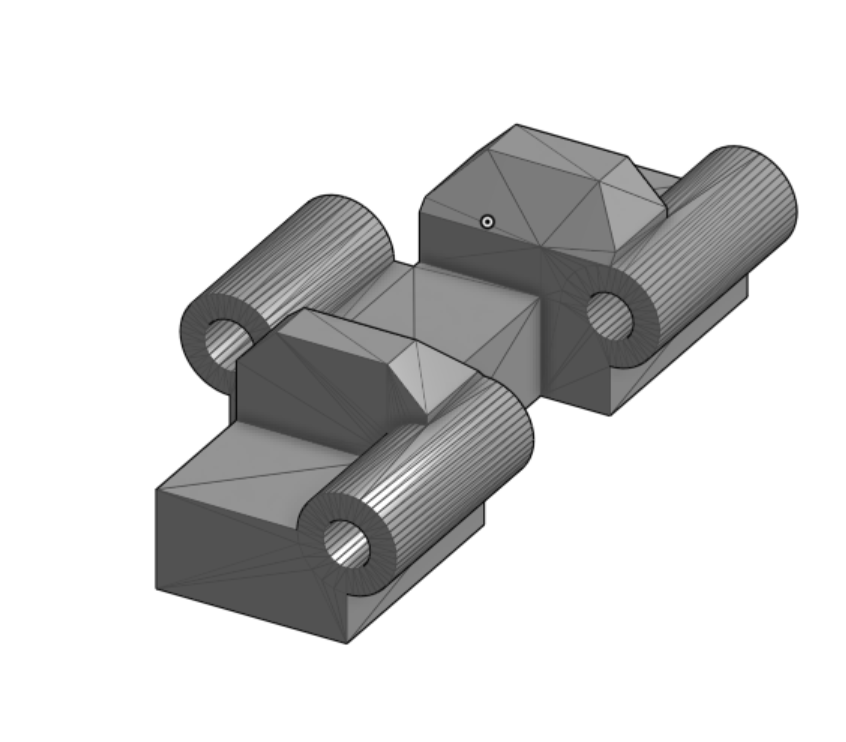
For brainstorming our exact vehicle design to reach this goal, we did something unique. By coming up with the worst ideas, we figured out what to avoid, and accidentally stumbled onto good ideas through creative thinking. - There are many components and stages we used and went through when prototyping this vehicle. At first, we planned on using an Arduino to control the vehicle, but later discontinued that idea after realising that it was a little bit overkill and we just needed it to go straight. We soldered DC motors, and stayed with our idea of using tank treads to build traction, and 3D designed components. The tank tread looks like this:
Our group decided to use paperclips to attach each of these treads together through the two cylindrical holes. We later found after the first testing day that the paper clips that attached the tank treads got caught in the exterior of the vehicle. The following photo is one we took in the initial prototyping stage. It is only one half of the rover and doesn’t include the chassis or the other duplicate of this (built slightly later).
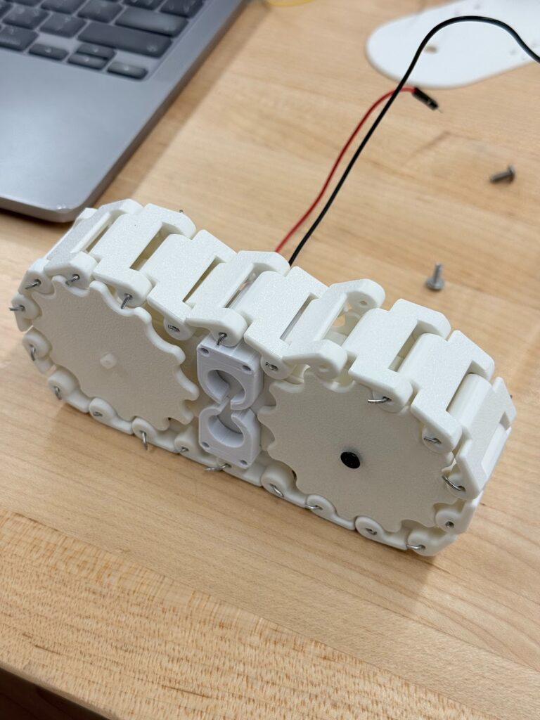
Each tank tread rover has one DC motor powering it, and here is what it looks like in action independently:
https://drive.google.com/file/d/19VbafLCue4fUbuSDJNwZSzcmSvVea2C_/view?usp=sharing
Michael has the CAD designs for the rotating gear we can see in the image and the other parts of the vehicle. Here is what the vehicle looks like in a slightly more progressed stage:
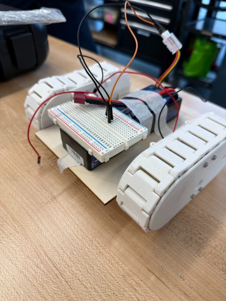
To explain what developments we had between these two images, I will go through the process component by component. We simply created another one of the tank tread rovers and added a 3D printed cover for the internals and gears. This serves an important function for the safety of the internals on Callisto. Also, in the first image if you look carefully you’ll notice that the treads are a bit loose. We fixed that by removing one singular tread to make it fit tightly. Another main component is the chassis. On our first test day, we quickly attached it with screws into the previously laser-cut holes. We also used screws to attach the 3D printed plastic on the side of the rover (the one that covers the internals). Inside each of the rovers are a DC motor, and soldered wires. We used a breadboard to distribute battery power to both motors. This is the main design, and after this we mainly made tweaks to optimize directional movement, weight distribution and centre of gravity.
After our first test, we fixed the paper clips issue (kept getting caught when rotating) by replacing them with small metal rods which we sawed. This was a simple and easy fix, but the challenging part was getting the measurements right, and the time-consuming exercise of cutting metal rods. The image above actually shows the version of our vehicle where we replaced the paper clips that were binding the treads together with metal rods. In class we also briefly experimented with the idea of placing the battery and the whole setup on the bottom of the vehicle to lower the centre of gravity. We dismissed the idea eventually because it would create lots of contact with the ground – possibly harming our components, creating friction and dents, and reducing speed. None of which we desire.
Later on in our prototyping and post-test stage (after the first test), we were aware of an issue. Our vehicle was moving slightly to one side when operating. We tried a variety of things such as screwing on our screws again to tighten them, and changing the order and placement of our components on the chassis. Ultimately, we concluded it was a weight distribution problem, and added various counterweights to balance the vehicle. The day before our final test, we went out and tested it – and it worked. Our vehicle climbed upwards, moved through rocky/dusty paths that resembled our testing plan. We were going to test if our vehicle could do these things the next day and if it could, it would indicate that it is Callisto-ready in the aspect we were hoping for.
Here is a link to a video showing our vehicle drifting to one side:
https://drive.google.com/file/d/1wuQP8vFziqLjFUxXm44jP1bzDjIydTKm/view?usp=drivesdk
The following link shows the video where our vehicle moves in a straight line over a gravel road, a non flat surface, the day before our final test:
https://drive.google.com/file/d/1fFlg4BAhU8V9A5GuMU7MoV80yBsHB-DC/view?usp=drivesdk
On our final test day, we didn’t have everything go to plan. Our vehicle was being tested on a separate surface, but one that still represented Callisto accurately. We were testing it on sand and rocks – it was not easy for a vehicle to get traction, and our vehicle, which was weighted one one side, took a sharp turn to that side and went out of the tracks. The video is linked below for reference. One likely reason the vehicle veered out of direction is because the distribution of rocks could have been clustered in one spot, pushing our vehicle in the opposite direction. Here is the video link:
https://drive.google.com/file/d/1svGZp6kUUKKNfIEGIZUK5MpZ8OPa3C3Z/view?usp=drivesdk
We learnt from this process that repeated prototyping and improvements allows for improvement, and there is always a way to further strengthen a design. Vehicle design is a rewarding process and there’s a lot of learning that comes with it.
Testing / Data:
- We had two official tests of our vehicle, and I’ll go through them and what we learnt and how developed from each of them. On the first test day, we were a little rushed to get our chassis attached to our rovers through screws, and used a simple wooden plank with laser cuts. In terms of our performance, our vehicle didn’t perform as well as we would have expected in terms of it getting caught on the ramp sometimes, and the paperclip design interfering with the spinning of the treads.
On the official test day, we had a test set up with rocks and sand laid out. Our vehicle moves straight at first, but turns left really fast, and heads into the wall. This repeated multiple times, and we concluded it was likely that the rocks indicated the rocks were positioned to guide the vehicles left.
One way we could have possibly combated this, was to create separate suspension tools such as springs for each side of the vehicle. This worked for another group that 3D printed some of their parts and used lego for others. Our chassis was a wooden board that we laser cut the holes into, so I feel that if we spent more time working on the suspension, it may have been more stable. When the vehicle moved, if one part got guided to the left, it would force the whole vehicle that way. This is not a problem that we anticipated, but it is a valuable real world lesson that we learnt. Our vehicle operated well on flat surfaces, but wasn’t able to go in a straight direction when confronted with adverse terrains. - I have the speeds of our vehicle, across a certain timeframe with distance accounted for, using a Video analysis tool. However, I would like to mention that the data is not completely accurate because it started turning to the left, and didn’t make much horizontal movement, so it looks like the vehicle didn’t move very fast. It was just moving towards a different direction which could not be accounted for in the video analysis.
Here is the graph that tracks the vehicles horizontal movement in m/s from our video and the corresponding data table: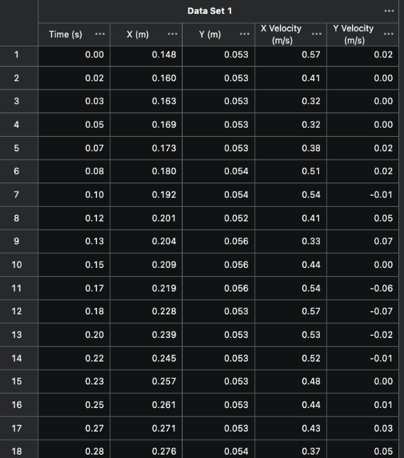
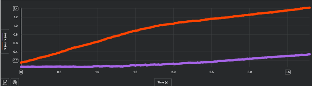
- Here are the calculations for efficiency. First, we need to recognise that the calculations are not accurate because the vehicle turned to the left and this analysis app registers velocity in terms of horizontal movement. Therefore, if a vehicle turned to one side and continued at the same speed that way, it wouldn’t have been recorded accurately. The peak speed of the vehicle could be accurate, but the slower increase after that isn’t right. Either the rocks slowed him down or the vehicle’s turning meant that it was recorded as less movement horizontally than was actually occurring.
Analysis:
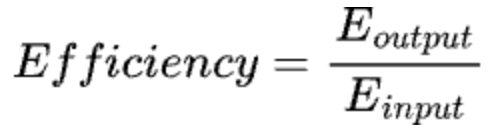
This is the formula to find efficiency. To find the useful total energy output, we need to find the kinetic energy of the vehicle, and the energy input by a formula.
I’m defining the energy output as the kinetic energy of the vehicle. The energy input is the electrical energy the battery provides which we estimated using the specifications on the battery. To be clear, I used Vernier Video analysis to find the velocity of the vehicle, and the motion speed was recorded in the presence of friction since it was driven on the ground. The calculated efficiency represents an estimate of how much of the battery energy was converted into kinetic energy, because some energy that the battery produced was lost to its surroundings through friction.
The kinetic energy of the vehicle can be found through the formula: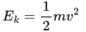
We estimate the mass of our vehicle to be around (1.183 kg), and through google sheets, I found the mean velocity of the vehicle using the data from the data table above. To be clear, I included every row in the calculations. Here is the mean velocity: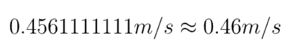
So now our equation for the Kinetic Energy is:
The energy input which we defined as the electrical energy supplied by the battery can be calculated by the formula listed in the calculations below. V is for the Voltage, I is the current in amperes, and the t is time measured in seconds.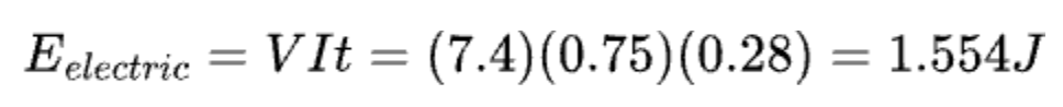
Therefore, the efficiency of our vehicle is: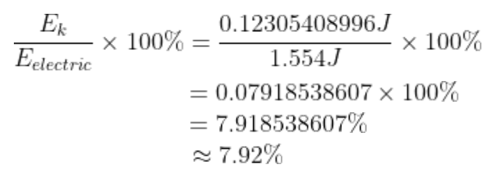
From these calculations, we know our vehicle efficiency was around 7.92%. I used the accurate decimal value for the calculations to prevent rounding errors from accumulating, but still preserved the estimates for coherence.- I used the following links to format my formulas: https://latex.codecogs.com/editor.html
https://latexeditor.lagrida.com/
https://editor.codecogs.com/
Conclusion / Evaluation:
From this design process, we learned that repeated prototyping and testing are essential to improving performance, because each iteration revealed new weaknesses and opportunities for refinement. There were always new things to add, whether it be replacing certain components, soldering wires, or adding a counter-weight. Testing reveals flaws that we don’t see coming otherwise. That’s why it’s such an important step in design.
It’s also really good to use data to help you figure out where you can improve. I was surprised to find out our vehicle only had almost an 8% efficiency rate, even though the design looks great and moves fast.
When the vehicle is used in real life, its performance may change due to factors like surface friction, uneven ground, and energy losses that were not fully present during testing. However, because the vehicle was tested and improved multiple times, it should still perform consistently. This project showed that vehicle design involves a lot of learning and improvement, and that good designs come from making changes based on testing results.
How the prototype affects the final scaled model:
The vehicle with an 8% efficiency actually wouldn’t have a great shot at making the round trip as it is. Realistically, it would be hammered with various types of radiation (some from outer space) and that would affect the vehicle’s physical ability and condition to perform even more. With the current performance, we’d need a lot more electrical energy/fuel than the vehicle would actually end up using. This problem would be further exacerbated if we replaced the battery with fuel, it would freeze on the planet.
One reason the efficiency was low, was low traction and difficulty to move. If we added a rubbery elastic tread covering to go around the tread , I think that would solve the efficiency problem.
The current battery produces a lot of power already, so if more of it is converted, our prototype would have functioned better. Also, we would have a scaled up version of the prototype on Callisto. One that could accommodate 4 astronauts. For this, we would need to scale the vehicle’s usable power to that similar to a sedan. It would require slightly less energy because it would have a simplistic design and therefore a lower mass. The current output of power of our vehicle is 5.55 W. This is partly in cause to the 8% efficiency rate, and also the power coming from a battery. We would increase the power to 100 kW on the scaled model for Callisto. The power source would still be battery, but ones similar to those in current electric vehicles. It would need to be adjusted in certain aspects to be weather and radiation proofed, but it makes sense to keep a similar power source as we scale up.
With this more efficient model (from the traction coating) and the scaled up power source, we predict that a working full size prototype would hold a charge of around 1,250 kWh. This is way more than it should be, but this is how much energy our vehicle would need to store in order to scale up if the efficiency remains at 8%. It is important to recognize that the other 92% of the energy is going to the surroundings, but not only as heat. It is also converting to sound, vibrational energy as the treads are on the rocks, and some energy is further lost as the vehicle tries to struggle and move on rocky terrains (in the prototype test).
AI acknowledgement
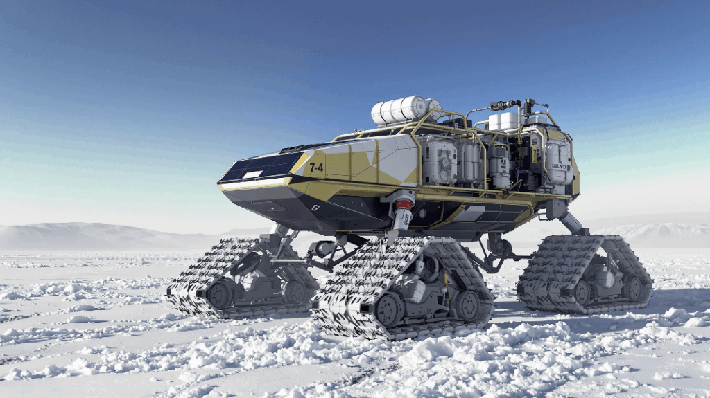
Our group used AI to create the image at the top of this blog post during our brainstorming phase. None of the work in this post is the result of AI use. I used AI to assist with the robotics component, but the transcript is not attached since we decided not to include any robotics.
Leave a Reply to Ms. Holmen Cancel reply