Introduction
This assignment was created to allow students to gain exposure and experience with Robotics, Arduino, and programming an Arduino board. The task requirements were to create something moving, and build a circuit that allows an Arduino board to interact with other components.
Circuit:
My idea
I chose to build a traffic directing system that has all the standard colours (green, yellow and red) and also a stop sign. The way this works is, each of the colours display for a few seconds, and then when the colour turns red, the stop sign comes down and acts as a roadblock. This is an idea similar to how there are barriers that block vehicles from moving near train lines. The idea behind this design is that it would improve safety on the roads and prevent people from taking dangerous risks like skipping red lights to see if they can narrowly make it. The incorporation of the stop sign ensures that even if somebody is tempted to squeeze past and make it through, they can’t. Overall, this is a safety-inspired design idea that could be taken further in the future.
Details of virtual prototype
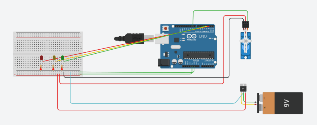
Breadboard, LEDs, GND and power:
The big white piece on the left is the breadboard. It allows multiple pieces to connect and leave from the same part. There are also blue and red rails that I have connected to the ground and 5V power pins on the Arduino board. The 5V is where the electricity is powered through and the ground (GND) is where it comes back. The circuit flows through 3 LEDs for my traffic system, and connects to the respective arduino pin. Each of the LEDs have a resistor on the same row to allow for a safe amount of current to go through. I used Ohm’s law to calculate the resistance required for my resistors. I had them all at 220Ω.
Servo, battery and regulator:
The servo is the blue piece on the right – it is what will move the stop sign. There is a wire connecting Arduino pin 9 and the servo to send control signals. The servo piece is meant to lower the stop sign as a barrier, then lift it back up, similar to that of a vehicular roadblock in front of trains. This is the piece that fulfills one of the two major requirements for this requirement: having a moving piece (and having the code to program it to move). I attached a 5V regulator to the 9V battery in the circuit to reduce the amount of current to a safe amount, because 9V is well above the required amount. The regulated 5V of current is sent to the servo. The servo is also connected to the Ground rail on the breadboard and the 5V rail.
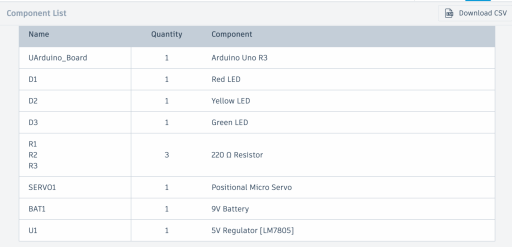
Bill of Materials (BOM)
Components required:
Code
Code:
#include <Servo.h>This tells the Arduino to include the Servo library which later allows us to control how it moves.
const int redLED = 2;
const int yellowLED = 3;
const int greenLED = 4;
const int servoPin = 9;
Creates variable for each LED and gives each of the LEDs a constant Arduino pin number.
Servo myServo;This creates a servo object called myServo – essentially defining it with this name.
void setup() {This line runs the code once when the Arduino starts up.
 pinMode(redLED, OUTPUT);
 pinMode(yellowLED, OUTPUT);
 pinMode(greenLED, OUTPUT);
This tells the computer that the LED will send signals on its output (whether it is on or off).
myServo.attach(servoPin);
}
This line attaches the servo to Arduino digital pin 9 so that the Aduino can send instructions.
void loop() {Runs the code forever
 digitalWrite(redLED, LOW); // Red light off
  digitalWrite(yellowLED, LOW);  // Yellow light off
  digitalWrite(greenLED, HIGH); // Green light off
  myServo.write(180);  // Stop sign is lifted to one extreme (not blocking traffic any further)
  delay(10000);         // This position will be held for 10000 milliseconds (10 seconds)
The text after each double slash is the explanation for the line of code. This block of code turns on the green light and keeps the stop sign lifted so it is not obstructing. It stays in this position for 10 seconds.
 digitalWrite(redLED, LOW); // Red light off
  digitalWrite(yellowLED, HIGH); // Yellow light on
  digitalWrite(greenLED, LOW); // Green light off
  myServo.write(90);  // the stop sign is up - signalling driver to stop (after seeing the yellow light)
  delay(2000);        // this position will be held for 2000 milliseconds (2 seconds)
The text after each double slash is the explanation for the line of code. This block of code turns off the green light, turns on the Yellow light and keeps the stop sign lifted so it is not obstructing. It stays in this position for 2 seconds.
digitalWrite(redLED, HIGH);// Red light turns on
  digitalWrite(yellowLED, LOW); // Yellow light off
  digitalWrite(greenLED, LOW); // Green light off
  myServo.write(90); // servo is in the middle angle meaning the stop sign will be held in front
  delay(5000); // this position will be held for 5000 milliseconds (5 seconds)
}
The text after each double slash is the explanation for the line of code. This block of code turns off the yellow light, turns on the red light and drops the stop sign to the middle angle so that it barricades traffic. It stays in this position for 5 seconds.
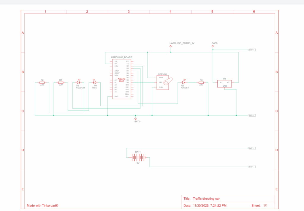
Physical prototype
Unfortunately I was unable to create a physical prototype due to technical errors on the Arduino IDE. However, I learnt a lot about robotics, through learning the programming, safety methods and how Arduino boards work. At the start of this project, all of this seemed overwhelming, but I took it one step at a time, from exploring ideas and planning, to developing it in TinkerCad. This has been a valuable learning opportunity and I look forward to the next opportunity to apply these newly developed skills.
Since I could not create a physical prototype, here is the circuit diagram and a screen recording of how my prototype works.
Circuit diagram:
Screen recording:
https://drive.google.com/file/d/1055csxvJikc230yCfZwdoriFzZnIfw6K/view?usp=sharing
I used minimal AI to help me pinpoint why exactly my servo wasn’t working. Unfortunately, since I was using my personal gemini account, the chat didn’t save and I don’t have access to the transcript. AI was not helpful at interpreting images and finding the error. It did however end up providing me with a long checklist of my wiring where I figured out where I messed up.
Leave a Reply to shayanc Cancel reply