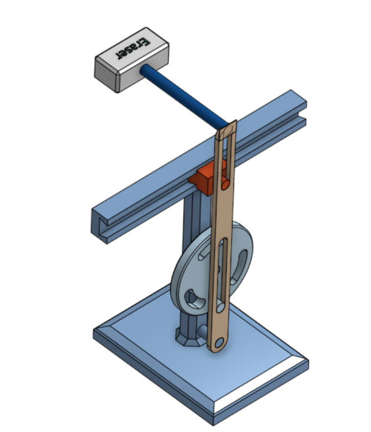
I built a CAD model for a Multi-Purpose Robotic Arm. I got inspiration for this idea from a video about Quick Return Mechanisms, and modified it into my own design. My build is a Quick Return mechanism (Robotic arm with changing speeds) with some modifications to hold an eraser and move it. The robotic arm can be purposed into several applications. In this version, it has been designed as a Robotic Arm Eraser. This is a step towards building a useful classroom tool.
Disclaimer: No AI use, only Onshape teaching and tutorial material (referenced below)
Skills to be demonstrated for successful assignment:
Sketch, Extruding, Assembly, Mechanical Drawings, BOM (Bill of materials)
Sketch
I drew sketches of all the individual parts for designing this 3D build. All of the sketches are available on the 3D build itself which are accessible through this Onshape link. For example, the Robotic Arm sketch below:
Extruding
Extruding is the act of expanding a 2D sketch into 3D. This is how I formed all of my parts for this assignment. To have a look at every extrusion, please check out the Feature list in my Onshape build. Here I used extrusion to create my eraser:
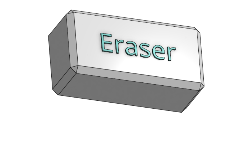
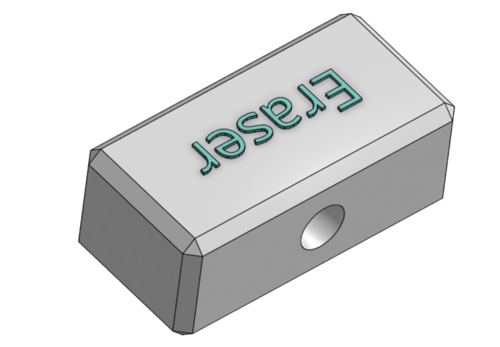
This part of the design shows my application of a Quick Return Mechanism. To create the eraser, I used a combination of the following techniques: Sketching, chamfering and extrusion. This eraser prism was built with 2 parts. The front half of the prism had a hole to fit the connecting cylinder, and the second half would make contact with an external surface to erase. I created the second half without the continuing hole else, to not have a cylinder poking out.
Assembly
Assembly is where all the designed parts are put together as a working model. There are connectors holding pieces together, called mates. There are different types of mates. Mates allow pieces varying degrees of freedom, from fixing them in place, sliding them along an axis, to revolving.
I have used different types like Revolute mate (revolving), Slider mate, Fasten mate (fixes in place), Tangent mate (makes faces touch without crossing).
For example, the slider mate was used to move the slider horizontally along the rail: Slider Mate Animation
Mechanical Drawings
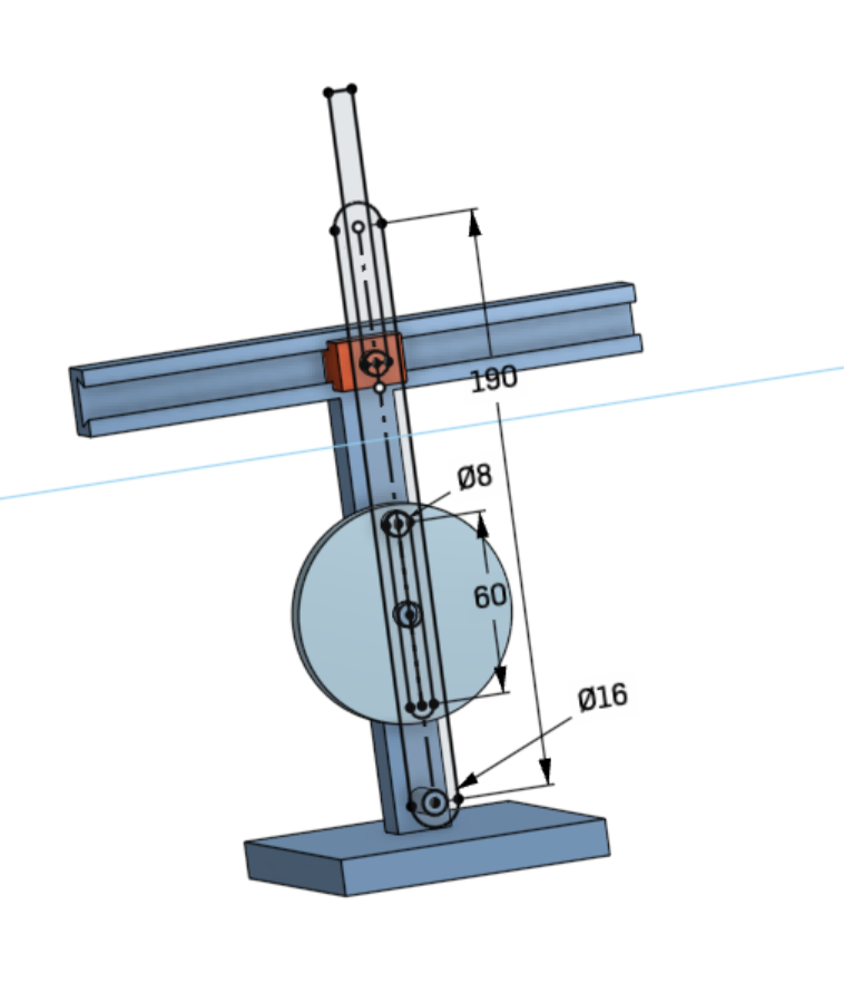
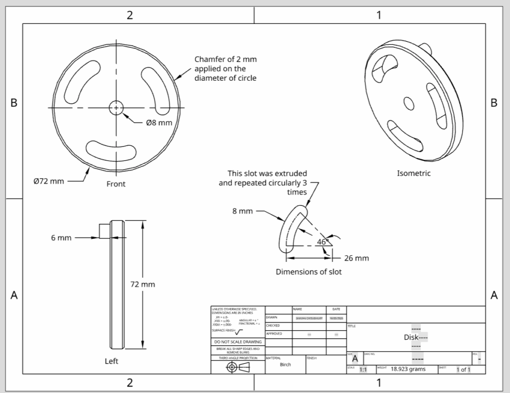
Mechanical Drawings are an important tool for engineers to express the dimensions of their products and for people to reproduce a build. This drawing contains the detailed dimensions without redundancy, and clearly diagrams the product from multiple views allowing for others to try to build it as well.
For example, mechanical drawing of disk (wheel) for Robotic Arm:
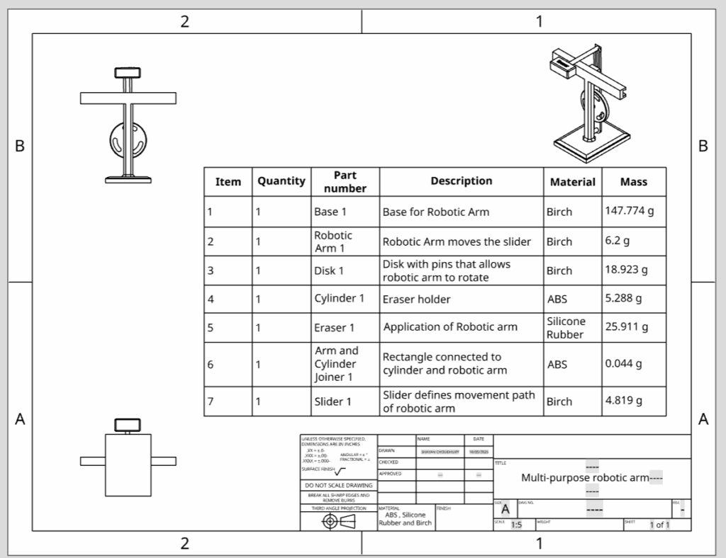
Bill of Materials (BOM)
A bill of materials shows the materials used in a product, along with the details of it. This is usually presented in the Assembly Drawing. It shows detailed information for the product which the designer wants to convey. For example these can include mass, material, colour, quantity. This is also helpful for businesses to order specific parts of the product as needed.
Leave a Reply to mcrompton Cancel reply