I’ve officially begun my project, which focuses on designing a technologically enhanced Xiangqi piece. The idea is to create a physical game piece that can house internal systems like micro-movement mechanisms and circuitry, essentially blending a traditional board game with modern engineering.
At its core, the problem I’m trying to solve is this: how can we preserve the physical and cultural feel of Xiangqi while introducing intelligent or mechanical functionality into each piece? This project is aimed not only at players, but also at anyone interested in robotics, design, and human-interactive systems.
My working goal is to design a piece that is compact, functional, and structurally capable of holding internal components without compromising its form.
Current Progress
So far, I’ve started building the first rough draft of the piece using CAD software (Onshape). This part of the process has been both productive and surprisingly enjoyable—especially rediscovering tools like extrusion and edge smoothing, which helped shape the overall structure.
Right now, the design consists of two main parts:
Main compartment: This acts as the primary housing for future components. At the moment, it’s a simple shell with an internal wall, but it establishes the space I’ll be working with. One highlight here was smoothing out the walls, which gave the piece a much more refined and realistic feel.
Lid: A basic top cover that will eventually seal the internal systems. In the future, I plan to engrave characters onto the lid to maintain the traditional Xiangqi aesthetic.
Combined, these form a very early prototype of the casing. It’s still simple, but it sets the foundation for future iterations where more complexity will be introduced.
Research and Direction
My research is still in its early stages, but I’ve identified three major areas I need to explore next:
Micro-bots or mechanisms for movement
Methods of connectivity (how components communicate)
Internal circuitry and power systems
Out of these, movement will likely be the most challenging and important part, since it directly defines how the piece interacts with the board.
Challenges
Looking ahead, there are a few major challenges I expect:
Fitting all necessary components into a very limited space
Designing a reliable and efficient movement system
Preventing the interior from becoming overcrowded
Maintaining a balance between functionality and clean design
The biggest concern is definitely the movement system, as it requires both mechanical precision and efficient use of space.
Next Steps
For the next phase, I plan to:
Dive deeper into research on micro-movement systems
Begin thinking about how internal components will be arranged
Update the CAD model to include compartments and mounting points
Continue iterating on the design as new ideas come in
Hi everyone, I’ve made quite an important decision. I’m going to start regularly posting about the progress of the project, as a way to keep track of my own work. I plan on reading all of these posts in order at year’s end, so I can look back at the highs and lows.
Also, every class I set myself a goal, no matter how big or small, and I try to achieve this goal before the end of class. This is so that I have something to work towards to, instead of drifting aimlessly for each class.
Also, I feel like it would be a nice personal touch if I included what music I was listening to as I worked on todays goal.
Anyways, Here lies the beginnings of my project.
Today’s Goal:
Design the rough draft of the piece
What I did today
Today I started the design of the xiangqi piece on the software CAD – onshape.
As I’ve said in a previous post from a very long time ago, Onshape brings back many memoires from grade 8, where my drafting class was designing a plane with Onshape. fun times. Anyways, I’m having a lot of fun rediscovering cool things such as rounding out the corners, making and extruding circles in different techniques, and more.
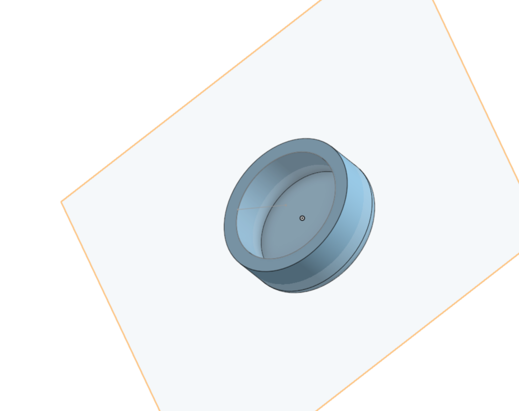
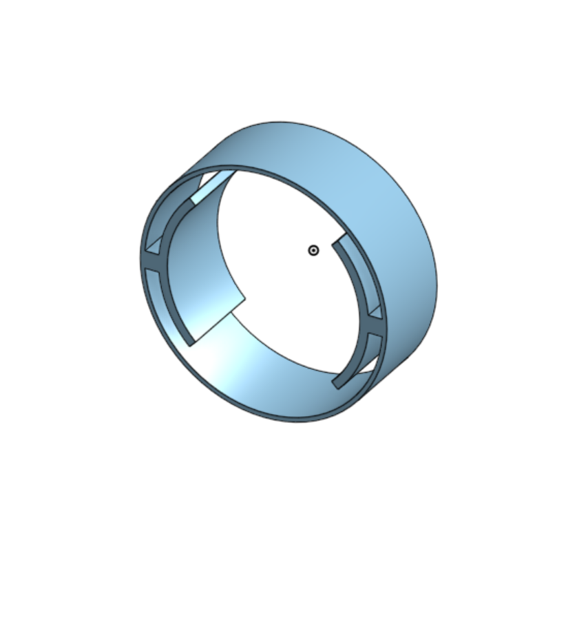
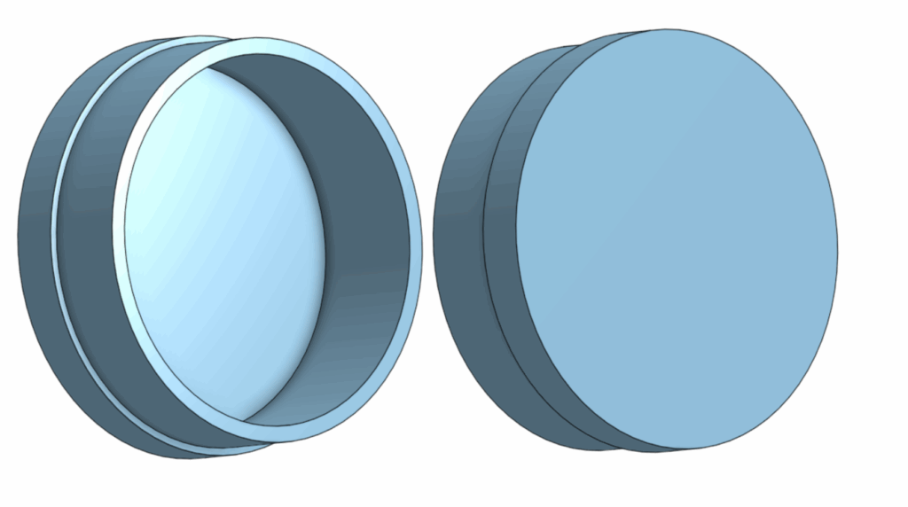
The Main Compartment
This is the main compartment (for now).
Its currently just a shell and a wall, but the most enjoyable part of this is was the smoothing out of the walls. very cool.
In the future, I’m going to make separate compartments for the micro-bots and circuitry, along with rivets for wheels.
The Lid
Nothing too extraordinary, just a lid for the main compartment.
On the top part of this lid, I plan on simply engraving on a few characters after the finished printing process.
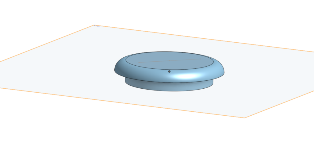
Full View
Combined, it would look roughly like this. the lid would cap on to the main body, holding in the future tech inside. Currently it doesn’t look like much, but there will be multiple iterations where we can see the evolutions of this casing, and hopefully with some live tests.
Conclusione e programma per i prossimi tempi
Overall a decently productive day to start this project. I’ve achieved my goal for this class, which is really nice, and I had some really funny conversations with friends to keep the mood light.
For next class, I’m going to do some research on a few things.
Micro-bots
methods for connectivity
internal circuitry
Probably, I’m going to put a considerable amount of emphasis next class to the micro-bots, especially for moving the pieces, as I think that would be one of the hardest parts to this project.
Osservazioni Conclusive
With that being said, my research will (most likely) be posted on the next blog post, so don’t forget to look at that!
Hi everyone. Its started. Our biggest, most complicated project of the year. The Personal Project.
Basically, the personal project is, well, our own personal project (wow!). We find something we’re passionate in, and research, develop, prototype and present it. This is the very simple, very watered down of my next 110 days or so.
Anyways, here is the overview to my project.
Project description
I’m going to build an automatically moving Xiangqi set, where people with the same board can connect to a platform via Bluetooth or another method (platform TBD-most likely xiangqi.com) and play against each other through the board. This new chess product will help people all over the world connect together and be able to experience what the game is about, with the feel of a real board and the imitation of a real opponent playing in front of you.
Prototype design
The prototype will (most likely) have two looks.
Magnetsand wheels: There will be circuits and magnets inside the board which will communicate with the pieces. The pieces will have extending and retracing wheels to physically move itself to its designated position, with magnetic guidance.
Robotic arm: A robotic arm is attached to the board with some form of connection, and with either magnetic sensors that communicate with the arm (like the first option) or an onboard camera pick up, move the pieces around like a hand.
Testing the Prototype
How am I going to test my prototype, you mat be asking. Wonderful question! I don’t know. I think depending on how much I can of this project I can complete, I will either:
test individual pieces (one or many) on one board, observe the wheels moving, the magnetic tracking, and the boards systems.
Build two sets of boards and pieces, and test the correspondence of the pieces moving on both of the boards (if everything above is achieved)
List of (potential) materials
Arduino boards
Wood
3D Printer
magnets
circuitry
Xiangqi pieces
wheels
Prototype creation (not in order)
I may work on some of these at the same time!
—————————————————————–
Design and work out the board: 2-3 weeks
First, I’m going to design the board, which will fit the circuits, magnets, and communication devices that will talk to the pieces.
Design pieces: 2-3 weeks
Next, the pieces will have extendable and retractable wheels, along with a method to connect to the board and the system.
Print the board, attach circuits and tech: 3-4 weeks
I would need to figure out how and where to put all the circuitry, the communication devices, and everything in between,
Build the pieces: 4-5 weeks
After the board, I would need to individually build 34 pieces, connect each piece to the main connector, make sure they all work along with each other, and troubleshoot any potential problems.
Coding: 3 weeks
I would then need to code the entirety of the game, including the niche rules like the flying general 飞将, how the cannon works and how the horse’s movement and collision physics would work as well. If I’m going to be honest, this is the part where I’m most concerned about, as I can’t code for sh*te.
What I plan on doing
There are a few things that I need to do to have a chance at succeeding in this project.
I’m going to be taking inspiration from the brand product “Chessnut”, and am probably going to buy a set to see how it works.
I also need to learn circuitry, different wireless connections, server hosting and maintenance, and coding.
If everything goes well from the above, I will then need to convince xiangqi.com to collaborate with me for this project. (more on this in a future post)
Conclusion
I have high hopes, but am also quite nervous. This is a do or die project, as I am (to my knowledge) one of the first people in the world to do this for this specific board game. If this works, I would be absolutely delighted, but I can already foresee that there are going to be many highs and lows, unexpected fails and massive successes, satisfying and frustrating moments and everything in between.
For now though, I’m truly exited to start, and I have already prepared and visualized many things to make this project (hopefully) smoother.
Hi everyone, This post is gonna be about the planet exploration project.
If you’ve seen my previous post, then you know what’s going on.
Before we continue, I’d like to disclose that AI (artificial intelligence) was not used in this post.
Introduction / Abstract
The goal of this project was to design and test a vehicle capable of traversing the moon Enceladus through underwater exploration. Given the presence of oceans beneath Enceladus’s icy surface, our team chose to approach the problem from an aquatic perspective and explored the possibility of a submarine-based vehicle.
Our definition statement was: The four astronauts operating the vehicle need to be able to operate and traverse in cold underwater temperatures of −201.67 °C, uneven terrain, maintain stability under high-pressure conditions, and remain energy-efficient so the vehicle can travel at least 10 km on a single energy supply while minimizing environmental impact for future missions.
Testing was intended to evaluate whether a submarine design could realistically achieve basic functionality, including buoyancy control, propulsion, and energy efficiency. The purpose of the test was to determine whether the concept was viable or fundamentally flawed and to identify major design failures early in the process.
Method / Procedure
The final proposed solution was a submarine-style vehicle designed for underwater travel. CAD models were created for the full vehicle as well as for individual systems, including propulsion and buoyancy compartments. A physical prototype was constructed based on these designs.
Here are CAD images for the individual parts of the submarine
Motor holster: Designed to hold the motor still as it spun.
Motor housing: A compartment for the motor to sit in, shielding it from the water ballast compartment
Sealant caps: Seals off the internals of the submarine from water
Main Body: this includes the motor housing and the water ballasts.
The testing procedure involved submerging the prototype in water and evaluating buoyancy, movement, and propulsion. The motor was first attached to a magnetic holster system intended to transfer rotational motion to an external propeller. Once powered, the submarine was sealed and placed into the testing environment.
During the build and testing process, numerous failures occurred. Initial tests revealed that the motor did not provide sufficient usable torque and that the magnets were too strong, causing the motor to stall. After changing the magnets, it became clear that internal magnetic friction prevented effective motion transfer to the external propellers. The motor was then replaced, which allowed the propulsion system to rotate, but not in a controlled or usable way.
Buoyancy testing revealed that the submarine was incapable of sinking. In response, a second compartment was added to allow water intake and increase mass. However, this solution was poorly implemented and ultimately ineffective.
From the beginning, the prototype was not test-ready. A basic design oversight; no on/off switch caused the motor to run continuously, making controlled assembly nearly impossible. Attaching the motor and propulsion system became a struggle. When the internal motor was finally secured, the external propeller could not be attached because the motor spun too quickly and the magnetic coupling was far too weak to catch and maintain alignment.
The buoyancy system failed entirely. The ballast compartment was insufficient and did not allow enough water into its compartment to overcome positive buoyancy. As a result, the submarine never submerged and could not perform its intended function.
No meaningful quantitative data was collected. The prototype never achieved propulsion, movement, or submersion. Before any measurements related to speed, energy efficiency, or maneuverability could be taken, the propulsion module detached during the third attachment attempt and broke, ending all further testing.
In summary, the test produced no usable data and demonstrated that the prototype was mechanically unstable, poorly integrated, and not functional enough to validate any aspect of the design.
Analysis
Because the prototype failed to function, no quantitative data was available for formal analysis. No calculations, graphs, or energy efficiency measurements could be produced.
However, the lack of data itself is significant. The failure shows that the design did not meet the requirements for testing. Issues included motor control, ineffective magnetic coupling, buoyancy, and weak structural connections (i.e the propellor). These problems show that the design was conceptually flawed and not ready for real world testing.
As a result, the energy efficiency of the design could not be calculated, as the vehicle never achieved propulsion or sustained motion.
Analysis pt 2
Since our experiment yielded zero results, a hypothetical analysis was conducted using assumed operating conditions.
Based on our hypothetical analysis, the total energy input to the system was estimated to lie in the range of 130–180 J for distance covered. This estimate comes from the assumption that the submarine maintained a constant velocity of 1 meter per second, and that an electrical current of 1 A was supplied to the propulsion circuit from a 6V battery.
An overall system efficiency of 15% was assumed to reflect realistic losses due to electrical, mechanical, and hydrodynamic inefficiencies.
Efficiency = E-useful / E-imput
E-useful is the energy used for propulsion. The useful energy required for the submarine to travel a distance of one meter was calculated to be approximately 9J per meter, which corresponds to 15% of the estimated input energy per meter.
E-useful=Efficiency x E-input
An overall efficiency of 15% represents an exceptionally strong performance for a small-scale underwater propulsion system.
Conclusion / Evaluation
The project did not result in a functional prototype. However, it clearly demonstrated the consequences of inadequate system integration and insufficient testing preparation. The design failed to meet basic operational requirements, including controlled propulsion, buoyancy adjustment, and structural stability.
If the project were to be continued, improvements would include adding a proper motor control system with an on/off switch, eliminating or redesigning the magnetic propulsion coupling and implementing a reliable ballast system with sufficient water capacity.
In its current state, this design would not function in a real Enceladus environment and would fail immediately under extreme temperature and pressure conditions.
Personal Note
I would like to note that I personally did not support the decision to build a submarine. My original proposal was to design a simple rover, which I believed would be significantly more achievable given the time and technical constraints of this project. However, one group member initially suggested the submarine concept in a persistent, joking manner, and the group fully supported pursuing it. As a result, the team committed to a submarine design despite its complexity.
Looking back, this decision directly contributed to the project’s failure. The submarine concept introduced avoidable challenges in buoyancy, propulsion, and sealing that were beyond our team’s capabilities under time constraints.
For this blog post, I’m going to talk about our new project: the Planet Exploration Project. I’m short, we will find a place of residence most suitable for humans, much later into the future.
Before we begin, I did not use AI or any large any LLM’s to help with my research.
I’m going to answer the following questions:
What celestial body did you choose and why?
What opportunities present themselves on your new home planet?
What challenges do you foresee?
What implications might there be for vehicle design?
How do we know what we know about your planet? Be specific. What research was done? What devices were used? How did those devices collect what data, and what conclusions can be drawn from them? What report speaks specifically to this information?
Alright. First question: What celestial body did you choose and why?
We chose Saturn’s moon Enceladus, because of its match to the criteria needed for life; the presence of liquid water, a source of energy, and a specific set of chemical elements. It also have a thin exosphere.
Second Question: What opportunities present themselves on your new home planet?
ESA International state that the plumes that shoot through the icy crust of the planet are rich in organic compounds, many are key for life. This is a great opportunity for researching extraterrestrial life. Further, This planet has water, which is the most crucial part of life, leading to opportunities to advance this planet in different sectors without having to worry about the basics. NASA also claims that there are hydrothermal vents releasing hot, mineral rich water into its ocean, which is also an opportunity for fertile soil when agriculture becomes relevant. The hot steam is also an opportunity for energy generation.
Third Question: What challenges do you foresee?
The first challenge I see instantly is how we are going to get there. Our destination is 1.3 billion kilometers from earth, so we would need a carrier ship capable of hosting generations of humans to our destination, Further on out transportation, it would be very difficult to time and route the course to its moon, as the moon constantly orbits its planet Saturn.
Another challenge i see its our acclimatization to our new planet, and our living arrangements. I see it very difficult for a generation of humans to go from a ship, which they have resided on for their entre life, to a moon with little to no information about. I think the shock would be tremendous, like going from a blazing hot shower to an ice bath.
Even if we mange to adapt, another challenge to overcome would be the moons drastic change in climate, as it only has a thin exosphere. For comparison: Earth’s atmosphere at sea level: 10¹⁹ molecules per cm, Enceladus: 10–1,000 molecules per cm³. That’s a trillion trillion (10²¹+) times thinner than Earth’s air.
Fourth Question: What implications might there be for vehicle design?
Vehicles on Enceladus would need to be completely reimagined to adapt to its extreme environment. First, the lack of a substantial atmosphere means traditional combustion engines would not work, so vehicles would need to rely on electric propulsion, nuclear power, or other non-air-dependent energy sources. The icy surface and plumes also present a challenge, requiring vehicles to be heavily insulated and resistant to extreme cold, with special traction systems to move across ice and avoid slipping.
Additionally, the thin exosphere offers little protection from radiation from the Sun and cosmic rays, so all vehicles would need radiation shielding to protect occupants. Mobility in low gravity, about 1/100th of Earth’s, would also change how vehicles accelerate, brake, and maneuver. Traditional wheeled vehicles might need magnetic tracks, hover systems, or treads designed for minimal gravity. Finally, vehicles may need to navigate through or around plumes of water vapor and ice particles, so their exteriors must be resistant to corrosion or damage from constant particle impact.
In short, vehicles for Enceladus would need to be energy-efficient, radiation-shielded, and engineered for ice, extreme cold, and low gravity while ensuring the safety of passengers in an environment that is harsh and unforgiving compared to Earth.
Last question: How do we know what we know about Enceladus?
Our understanding of Enceladus comes primarily from detailed observations by the Cassini spacecraft, which orbited Saturn from 2004 to 2017. Cassini carried several instruments that allowed scientists to study the moon in depth. The Ion and Neutral Mass Spectrometer (INMS) sampled gases in the plumes, measuring water vapor, carbon dioxide, methane, hydrogen, and other trace compounds. The Cosmic Dust Analyzer (CDA) collected tiny ice grains ejected in the plumes, allowing scientists to determine their composition, including salts and organic molecules. Imaging systems and thermal instruments mapped the surface, revealing fractures known as “tiger stripes” and areas of higher temperatures, indicating active geology and cryovolcanism. Data from these instruments showed that the plumes are fed by a subsurface ocean beneath the icy crust, and the presence of silica grains and chemical signatures suggests hydrothermal activity on the ocean floor.
In addition to Cassini, ground-based observations and space telescopes have confirmed the plumes extend far into space and contribute to Saturn’s E ring. Laboratory studies and theoretical models have helped scientists understand the ocean chemistry and energy sources, supporting the idea that Enceladus has the key ingredients for life: water, chemical elements, and a source of energy. These findings are summarized in several reports. NASA’s Science website on Enceladus provides an overview of the plumes, subsurface ocean, and Cassini data. The European Space Agency has reported on the detection of complex organic molecules in the ocean. Finally, in the article “Exploration of Enceladus and Titan: investigating ocean worlds’ evolution and habitability in the Saturn system” outlines the current knowledge of Enceladus and mission concepts for further exploration. Together, these studies show that Enceladus is an active world with a subsurface ocean and the potential for habitability.
Hedman, M. M., Dhingra, D., Nicholson, P. D., Hansen, C. J., Portyankina, G., Ye, S., & Dong, Y. (2018). Spatial variations in the dust-to-gas ratio of Enceladus plume. Geophysical Research Letters. https://arxiv.org/abs/1801.01567
Hirata, N., Miyamoto, H., & Showman, A. P. (2022). Particle deposition on Saturnian satellites from ephemeral cryovolcanism on Enceladus. Planetary and Space Science. https://arxiv.org/abs/2205.11265
Mitri, G., Barnes, J., Coustenis, A., et al. (2022). Exploration of Enceladus and Titan: investigating ocean worlds evolution and habitability in the Saturn system. Experimental Astronomy, 54(3), 877–910. https://doi.org/10.1007/s10686-021-09772-2
Villanueva, G. L., Hammel, H. B., Milam, S. N., Kofman, V., Faggi, S., Glein, C. R., … & Hedman, M. (2023). JWST molecular mapping and characterization of Enceladus water plume feeding its torus. Astrophysical Journal. https://arxiv.org/abs/2305.18678
Waite, J. H., Combi, M. R., Ip, W.-H., Cravens, T. E., McNutt, R. L., Kasprzak, W. T., … & Hansen, C. J. (2006). Cassini ion and neutral mass spectrometer: Enceladus plume composition. Science, 311(5766), 1419–1422. https://pubmed.ncbi.nlm.nih.gov/16527970/
For this post, I’m doing something very different. I’m building a simulation for an Arduino radar!
DISCLAIMER:
A big shoutout to Robotics India for the amazing ideas and tutorials on Arduino projects. Many of the concepts here were inspired by their work, and we’ve adapted them to fit the flow of this post. We encourage readers to check out Robotics India’s content for even more detailed insights and guidance.
Furthermore, I did not use any form of AI assistance in this project. Thanks!
This is my first time EVER doing something like this. Therefore, I’ve looked online for some ideas, and have come across the holy grail of videos.
Check it out!
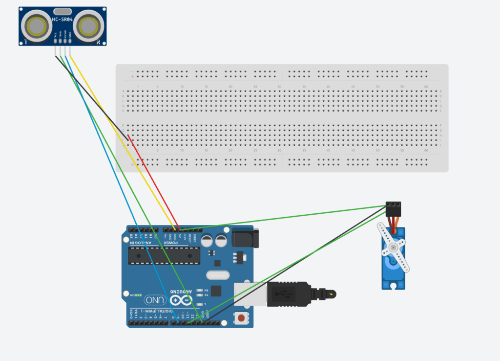
After watching the video, I decided to recreate the project myself, a mini Arduino radar system using an ultrasonic sensor (HC-SR04) and a servo motor.
DISCLAIMER: This code is heavily inspired by a YouTuber, and under no circumstances do I claim it as my own. I have, however, studied how the code works and believe I have a solid understanding of its functionality. My explanation within the code below reflects my own understanding and interpretation.
The basic idea is simple: the servo rotates the ultrasonic sensor back and forth, sending out sound waves to detect objects. The distance readings are then used to simulate a radar sweep, just like what you’d see on an actual radar screen.
The circuit sends out ultrasonic pulses, measures how long they take to return, and converts that time into distance. Then, the servo moves to a new angle and repeats the process, scanning the area in front of it.
Here is the BOM (parts list), and code below, along with an explanation of how everything works!
Component
Quantity
Description
Arduino UNO
1
The “Brain” of he circuit
HC-SR04 Ultrasonic Sensor
1
Sends and receives sound waves to measure distance.
SG90 Micro Servo Motor
1
Rotates the ultrasonic sensor to scan different angles.
Breadboard
1
Makes it easy to connect components without soldering.
Male-to-Male Jumper Wires
1
For all electrical connections between the components.
USB Cable (Type-B)
8
Used to upload code and power the Arduino.
#include <Servo.h>

// --- Pin Definitions ---
const int SERVO_PIN = 11;
const int TRIG_PIN = 8;
const int ECHO_PIN = 9;

// --- Constants for Servo ---
const int MIN_ANGLE = 0;
const int MAX_ANGLE = 180;
const int ANGLE_STEP = 1;
const int SWEEP_DELAY = 15;

// --- Constants for Ultrasonic Sensor ---
const float SOUND_SPEED_FACTOR = 58.2; // duration / 58.2 = cm

Servo myServo;

void setup() {
  pinMode(TRIG_PIN, OUTPUT);
  pinMode(ECHO_PIN, INPUT);
  myServo.attach(SERVO_PIN);
  Serial.begin(9600);
}

void loop() {
  sweepAndMeasure(MIN_ANGLE, MAX_ANGLE, ANGLE_STEP);
  sweepAndMeasure(MAX_ANGLE, MIN_ANGLE, -ANGLE_STEP);
}

void sweepAndMeasure(int startAngle, int endAngle, int step) {
  int angle = startAngle;

  while (true) {
    myServo.write(angle);
    delay(SWEEP_DELAY);

    long distance = calculateDistance();
    printData(angle, distance);

    if (angle == endAngle) break;
    angle += step;
  }
}

long calculateDistance() {
  // Trigger ultrasonic pulse
  digitalWrite(TRIG_PIN, LOW);
  delayMicroseconds(5);
  digitalWrite(TRIG_PIN, HIGH);
  delayMicroseconds(10);
  digitalWrite(TRIG_PIN, LOW);

  // Read echo with timeout (prevents freezing)
  long duration = pulseIn(ECHO_PIN, HIGH, 25000); // 25ms max = ~4 meters

  // If no echo → return -1
  if (duration == 0) return -1;

  long distance = duration / SOUND_SPEED_FACTOR;

  // Filter out unrealistic noise
  if (distance > 400 || distance < 0) return -1;

  return distance;
}

void printData(int angle, long distance) {
  Serial.print(angle);
  Serial.print(",");
  Serial.println(distance);
}
In short, it sweeps a servo back and forth while measuring and logging distances with an ultrasonic sensor.
It has been quite a while since I last posted, but I’m really excited to share my first official project created in Fusion 360! This marks my very first completed design using CAD software, and I couldn’t be happier with how it turned out. For this project, I decided to go with the first assignment option, a simple and meaningful task that allowed me to explore the fundamentals of 3D modelling, constraints, and precision design within Fusion.
Before diving into the details, I want to make an important disclaimer: I did not use any form of AI assistance in the creation of this project. Every sketch, extrusion, constraint, and adjustment was made manually by me. I wanted to rely solely on my own skills and understanding of CAD design principles to truly learn and develop some major points in my designing area. The goal was to create something that reflects both my personal effort and my growing comfort with Fusion 360 as a modelling tool.
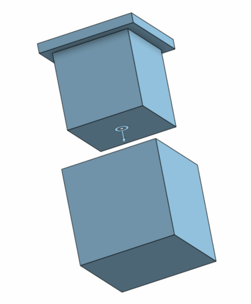
For my first project, I decided to model a moving box with a fitted lid, something functional but still detailed enough to challenge me. I started by drawing out the base of the box, then extruded the base upward to form the drawn section. Then, on a separate assembly, I worked on creating a smaller upper piece that would act as the lid.
The key part of my design was ensuring that the lid and box could interlock properly. To achieve this, I made sure that the extrusion of the first part was exactly the right size to fit into the indentation of the other part. This design choice allows the two components to slide together smoothly, forming what is essentially an airtight seal.
One of the most interesting and enjoyable parts of the design process was using slider mates to simulate how the two parts would interact in motion. This feature allowed me to show that the box and its lid could slide together naturally, replicating how they would behave if they were physically manufactured. I also made use of the parallel constraint, which ensured that the lid remained aligned with the box during motion and didn’t accidentally phase through the walls of the container. It’s a small detail, but it gave the model a very realistic feel, which was one of my proudest moments figuring it out.
Honestly, I think that alignment feature might be the part of my project that I’m most proud of. It gave the box a sense of realism that makes it look like something that I could actually touch in real life. Seeing the simulation of the lid sliding on perfectly and locking into place was a very satisfying moment. It really made all the earlier sketching and dimensioning work feel worth it.
After completing the modelling phase, I moved on to the technical drawing portion of the project. This step allowed me to document the box in a 2D format, complete with dimensions from all the important views. Translating a 3D design into a proper technical drawing gave me a much better appreciation for how engineers communicate design intent. While working on this stage, I noticed that a few parts of my box weren’t perfectly symmetrical. Some lines and edges were slightly off on the inside, likely because of minor inconsistencies in my original sketch dimensions. Even though it was a bit frustrating to spot those imperfections, I see it as a valuable learning experience. It reminded me just how important it is to plan and double-check constraints early in the process. However, the CAD software managed to “solve” this issue in the assembly part, which was nice to see.
Coming back to CAD after not doing it since grade 8 was honestly really nostalgic. It’s cool how something I learned years ago manages to connect to what I’m doing now, just with more patience and a stronger rig.
Looking back, I’m very proud of the final product, although it does look simple. I learned how to manage sketches, control constraints, and use assembly motion tools to test functionality, all within a single project. Even small details, like understanding how the “parallel” and “slider” constraints interact, made me feel like a true designer.
As I continue improving this design, my next goal is to fix the minor symmetry issues, and maybe, far off into the future, I would like to have a go at designing an F1 car.
This may only be a small project, but it feels like a big achievement for me personally. It shows that with patience, curiosity, and resilience, I can re-learn the fundamentals of design and apply them after years of not using this software. For now, though, I’m genuinely happy with how this simple moving box turned out, and I’m looking forward to sharing even more progress in the future.
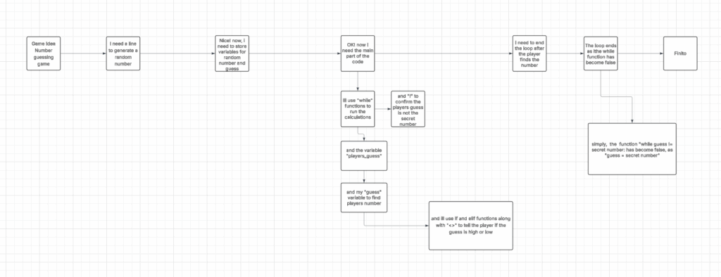
This line imports Python’s built-in random module, which allows the program to generate random numbers. We need it to pick a secret number for the guessing game.
def check_guess(guess, secret_number):
Defines a function called check_guess that takes the player’s guess and the secret number as inputs.
if guess < secret_number: print(“Too low! Try again.”)
Prints a hint if the player’s guess is smaller than the secret number.
Prints a hint if the player’s guess is larger than the secret number.
while guess != secret_number: while True: player_input = input(“Enter your guess: “) try: guess = int(player_input) break except ValueError: print(“That’s not a valid number. Please enter an integer.”)
secret_number = random.randint(1, 100)
Chooses a random number between 1 and 100 for the player to guess.
guess = 0
Initializes the guess variable so the loop can start
print(“I’m thinking of a number between 1 and 100.”) print(“Can you guess what it is?”)
Prints instructions to the player about the game.
while guess != secret_number:
Repeats the loop until the player guesses the correct number.
player_input = input(“Enter your guess: “)
Asks the player to type in a guess.
guess = int(player_input)
This Converts the players input from text to a number.
check_guess(guess, secret_number)
Calls the function to check the guess and give feedback.
print(f”🎉 You got it! The secret number was {secret_number}.”)
After the loop ends (player guessed correctly), prints a congratulatory message. The f in front of the message is like saying, ‘Hey, put the real number here!’ so instead of showing {secret_number}, it shows the actual number you were thinking of.