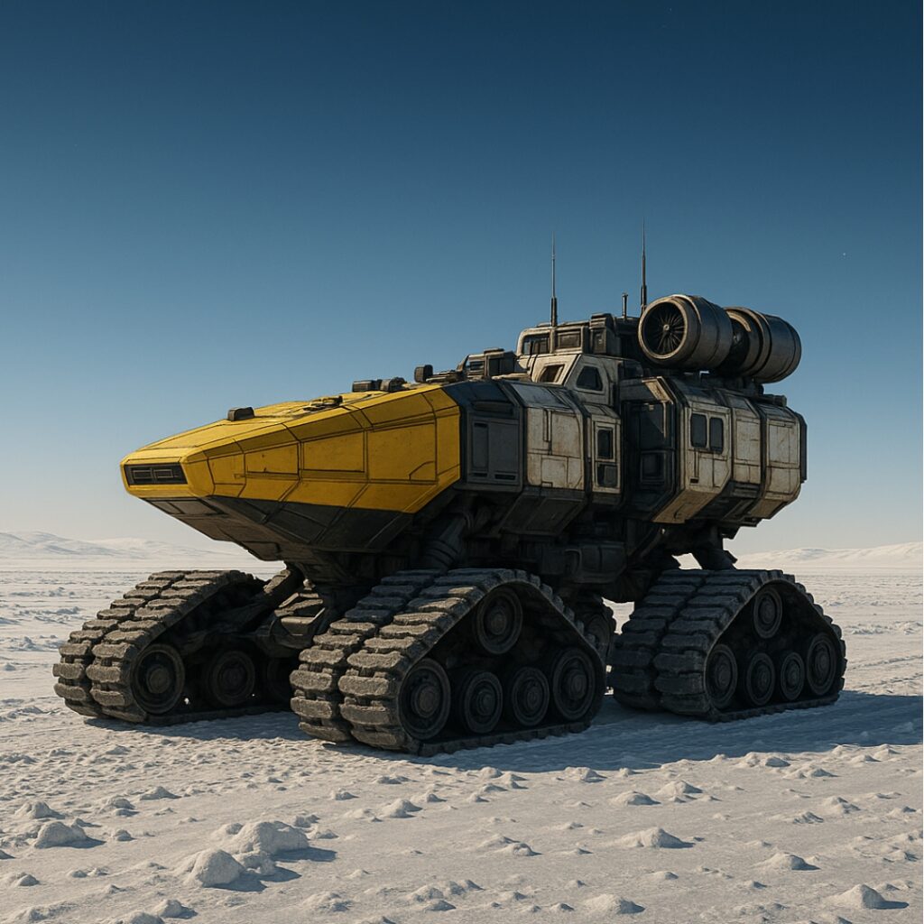
For the past several weeks, our group has been working on designing and building a vehicle capable of operating on Callisto, Jupiter’s second-largest moon. In the first blog post, we explored what makes Callisto a compelling destination: its position outside Jupiter’s deadly radiation belts, its stable and ancient terrain, and the possibility of a salty subsurface ocean hidden beneath kilometers of ice. But knowing about a place and actually building something that can work there are two very different challenges.
Our definition statement for this project was:
The vehicle must be capable of operating independently on Callisto, a remote, frozen, and airless moon with extreme cold (approximately −139°C to −190°C), low gravity (0.126 g), and weak sunlight (roughly 4% of Earth’s). It must generate its own power without relying on solar energy, maintain safe interior temperatures for its crew and components, and reliably traverse rocky, ice-covered terrain over a 5 km round-trip distance.
The purpose of our prototype and testing was to validate one of the most critical aspects of this design: whether a tracked vehicle can efficiently navigate rough, uneven terrain similar to what we’d expect on Callisto’s surface. We weren’t able to simulate every condition (vacuum, extreme cold, low gravity), but we focused on the mechanical challenge of traveling on rocky terrains and energy efficiency, which are directly tied to whether this vehicle concept is viable.
This post walks through our final design, the process of building and testing our prototype, the data we collected, and what it all means for our vehicle’s real-world performance on Callisto.
(You can view the initial research and planning in PEP Assignment 1.)
Method / Procedure
Design Evolution
Our vehicle went through several design iterations before we settled on the final concept. Early brainstorming included ideas like wheeled rovers, legged walkers, and even hopping vehicles. However, given Callisto’s combination of low gravity, rough cratered terrain, and icy surfaces, we kept coming back to a tracked (tank-tread) design as the most practical option.
The key reasoning was:
- Treads distribute weight over a larger surface area, which provides better traction on loose or icy ground compared to wheels
- Treads handle uneven terrain more reliably, climbing over small obstacles and crater rims without getting stuck
- The low center of gravity helps with stability, especially important given Callisto’s low gravity where a tall vehicle could easily tip
We then settled on a design with two independent track assemblies, each with one motor driving the tread.
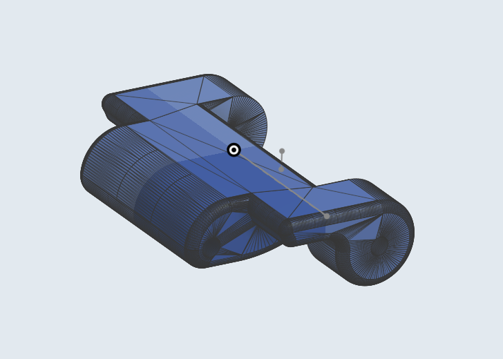
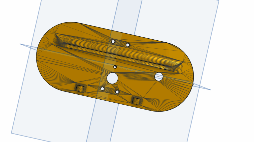
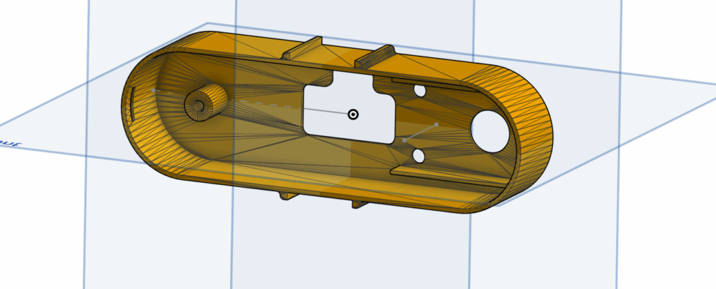
CAD Design
We built the full 3D model in OnShape. This includes, a chassis (though we later decided to switch to wood boards using laser cutting), track, gear, and holder. The chassis was designed with a hollow interior to hold electronics (battery, motor, and wiring), and the front of the vehicle was shaped to deflect debris and provide a lower approach angle for climbing obstacles.
Key design decisions in CAD:
- The chassis shell was designed to be 3D printable as a single piece that fits over the drive platform
- We included mounting points for the track assemblies on both sides
- The interior was kept hollow and accessible for wiring and battery placement
- The front profile was angled to help the vehicle climb over obstacles rather than collide with them
Track design that can be connected with each other to form a complete chain using metal rod
Inner and outer cases for the track component
Motor mount used to secure the motors
Bill of Materials
| Component | Quantity | Purpose |
|---|---|---|
| PLA Filament | As needed | 3D printed parts for track components |
| Chassis | 1 | Base drive platform |
| Tank Tread | 22 | Terrain traversal system |
| Axis | 22 pieces | Connects treads |
| Battery Pack | 1 | Power source |
| Motor | 2 | Speed and direction control |
| Jumper Wires | As needed | Electrical connections |
| Screws & Nuts | As needed | Securing removable components |
Prototype Build Process
Phase 1: Chassis Fabrication
We were planning to 3D print the chassis using PLA filament. But after further discussion around material use, weight, and size, we have decided to use wood instead. We have laser cutted the wood board and mounted all the components on directly using screws.
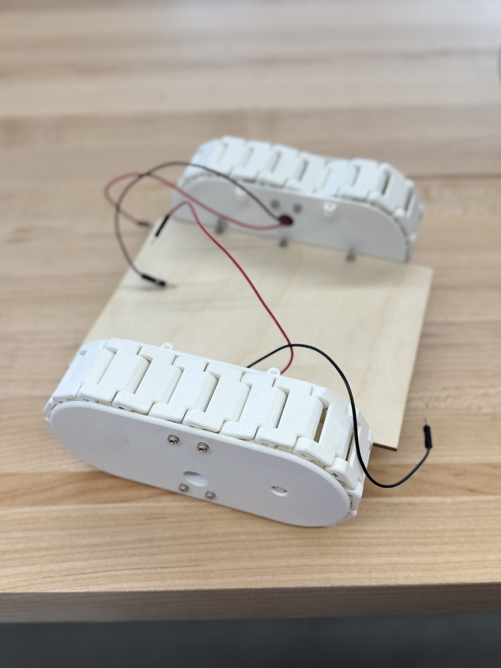
Phase 2: Track Assembly
After 3D printing all the parts needed. We have assembled them together into two identical track components. And mounted both track assemblies onto the chassis. This was one of the more challenging steps because the tracks needed to be aligned precisely, and even a small misalignment caused the vehicle to drift to one side. It was only later that we became aware of this issue. We tried to fix this issue by adjusting the alignment again, and using weights to counter act the drift to one side.
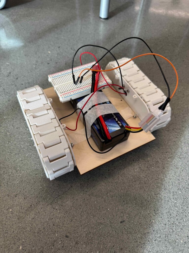
Phase 3: Electronics Integration
We have lowered the level of the chassis and in some trials we have placed the battery underneath the vehicle’s platform to keep the center of gravity low. This decision was intentional: on Callisto, with only 0.126 g of gravity, a top-heavy vehicle would be extremely unstable. Even for our Earth-based prototype, a lower center of gravity improved stability over rough terrain.
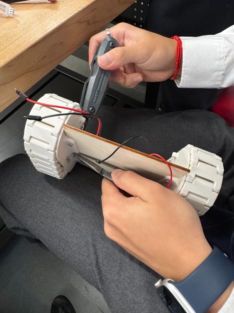
Phase 4: Iteration and Fixes
During initial test runs, we noticed the rover was drifting slightly to one side due to uneven tread tension, power ,and weight. We addressed this by:
- Re-tensioning the treads on both sides
- Ensuring both track assemblies were aligned properly
- Adding weights to balance out the forces
This iterative process of test → identify problem → fix → retest was one of the most valuable parts of the project. It showed us that even small manufacturing inconsistencies can have a big impact on performance.
Testing / Data
Test Design
Our testing was designed to evaluate two main performance areas:
- Terrain traversal capability: Can the rover reliably cross surfaces similar to Callisto’s cratered, rocky, icy terrain?
- Efficiency under load: How much does the rover’s performance reduce when moving from smooth surfaces to rough terrain?
We created the following test conditions:
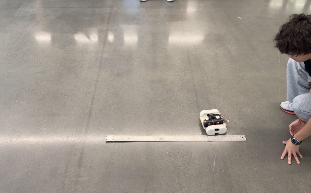
Control Test: Flat, smooth surface. This establishes a baseline speed and performance.
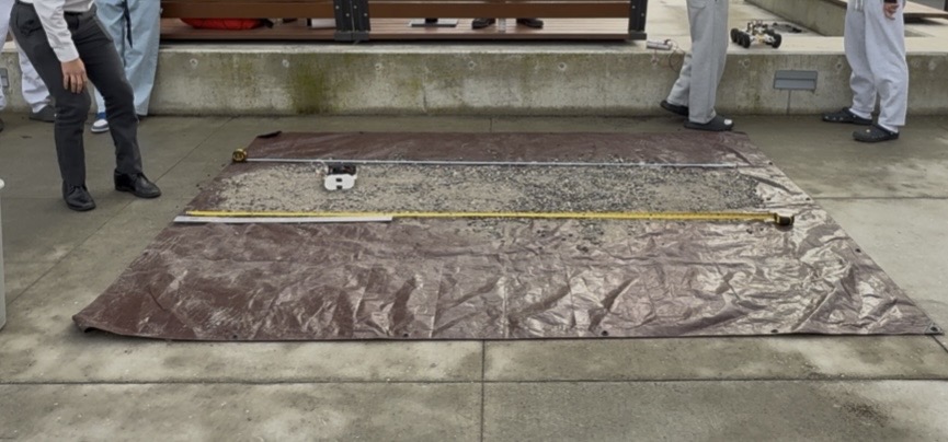
Test 1 — Rocky Terrain: Rocks and pebbles scattered on a flat surface, simulating minor surface irregularities on Callisto.
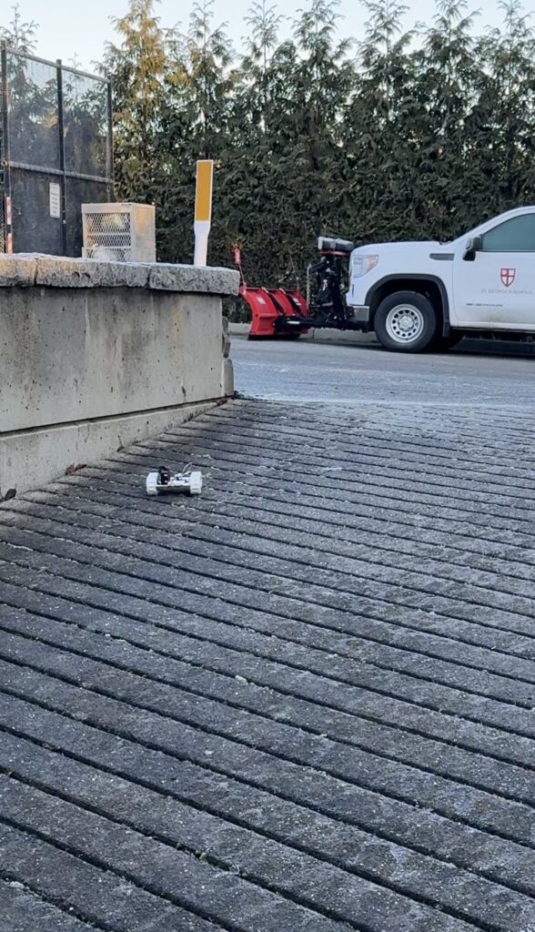
Test 2 — Inclined Terrain: Few amounts of obstacles along side with inclined hills, simulating crater rims.
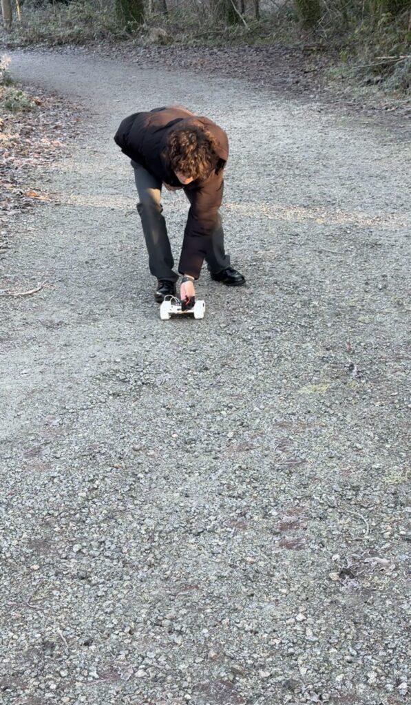
Test 3 — Inclined + Rocky Terrain: Significant obstacles including steep inclines and large rocks, simulating rocky areas between settlements and major terrain features.
For each condition, we ran the rover over a measured distance, timed each run with a stopwatch, recorded multiple trials for consistency, and used the same battery charge level across all tests.
Test Results
Control Test (Flat Surface):
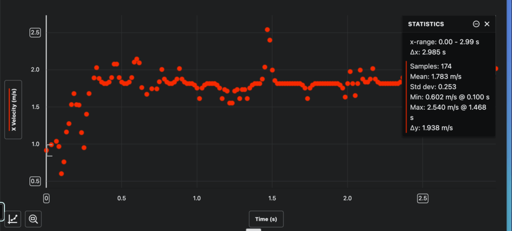
| Trial | Distance (m) | Time (s) | Speed (m/s) |
|---|---|---|---|
| 1 | 5.30 | 2.99 | 1.78 |
Test 1: Rocky Terrain
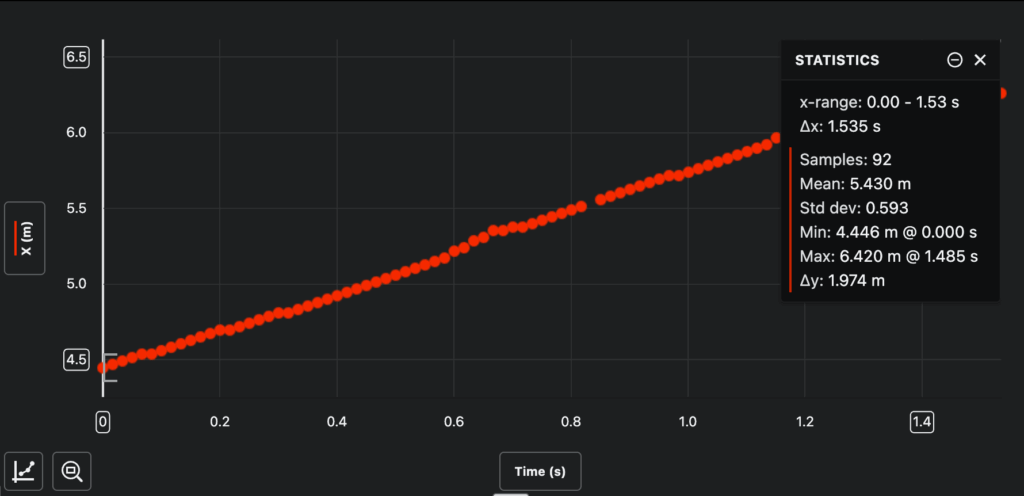
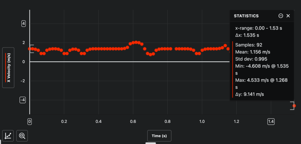
| Trial | Distance (m) | Time (s) | Speed (m/s) |
|---|---|---|---|
| 1 | 1.97 | 1.54 | 1.16 |
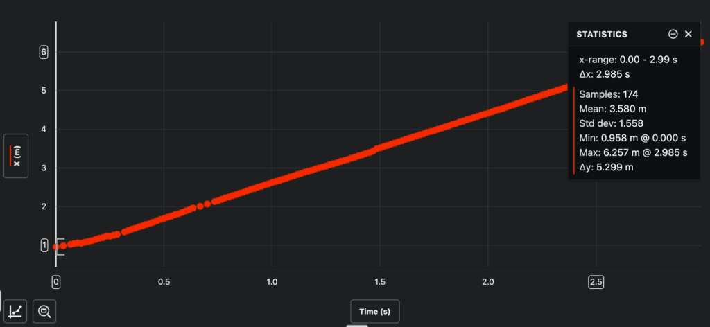
(The velocity and position graphs above were generated from the video analysis website to generate visual representations of the vehicle’s performance on each terrain type.)
Inclined Terrain:
For the inclined terrain test, we captured video footage of the rover navigating inclined terrain with minor obstacles. However, we did not include a meter stick or reference scale in the video frame, which means we cannot perform accurate position tracking or velocity calculations from this footage. The video qualitatively shows the rover successfully traversing the incline, but quantitative data is unavailable for this test condition.
| Trial | Distance (m) | Time (s) | Speed (m/s) |
|---|---|---|---|
| 1 | N/A | N/A | N/A |
| 2 | N/A | N/A | N/A |
| 3 | N/A | N/A | N/A |
| Average | No scale reference in video | ||
Inclined + Rocky Terrain:
| Trial | Distance (m) | Time (s) | Speed (m/s) |
|---|---|---|---|
| 1 | N/A | N/A | N/A |
| 2 | N/A | N/A | N/A |
| 3 | N/A | N/A | N/A |
| Average | No scale reference in video | ||
Observations During Testing
During testing, we observed several important behaviors:
Control Test: On the flat surface, the rover moved steadily with minimal deviation. The average velocity of 1.78 m/s was consistent throughout the run. We noticed the vehicle maintained a relatively straight trajectory, though there was minor drift to one side due to the motor imbalance we identified earlier.
Rocky Terrain: When traversing the scattered rocks and pebbles, the rover’s speed dropped noticeably to 1.16 m/s, which is a a 35% reduction from baseline. The treads handled the obstacles well, climbing over small rocks without getting stuck. However, we observed increased vibration and occasional slipping happen when encountered with larger pebbles. The vehicle’s low center of gravity proved valuable here, as it remained stable despite the uneven surface.
Rocky + Inclined Terrain: While we captured video footage of these tests, the lack of a reference scale prevented quantitative analysis. Qualitatively, we observed the rover successfully climbing inclines and navigating combined rocky, inclined terrain, though visibly the speed was reduced and occasional wheel slippage on steeper sections.
Analysis
Speed and Efficiency Calculations
I have chosen to define and calculate the efficiency in two separate ways. One is to test it’s efficiency in converting speed on flat surface to rocky terrain. The other is how effectively it converts energy input from the battery into useful energy output (kinetic energy).
To measure our vehicle’s efficiency, we compared its speed on each terrain type to its speed on the flat control surface. This gives us a percentage that represents how well the vehicle maintains performance under increasingly difficult conditions:
Efficiency Formula:
Efficiency (%) = (Speed on terrain / Speed on flat surface) × 100
Given Data:
• Vehicle mass (m) = 1.184 kg
• Control test average velocity (v₁) = 1.78 m/s
• Rocky average velocity (v₂) = 1.16 m/s
Kinetic Energy Calculations (KE = ½mv²):
Control Test:
KE₁ = ½ × 1.184 kg × (1.78 m/s)²
KE₁ = 0.592 × 3.168
KE₁ = 1.88 J
Test 1 (Rocky Terrain):
KE₂ = ½ × 1.184 kg × (1.16 m/s)²
KE₂ = 0.592 × 1.346
KE₂ = 0.79 J
Terrain Efficiency:
Efficiency = (v₂ / v₁) × 100%
Efficiency = (1.16 / 1.78) × 100%
Efficiency = 65.2%
This means our vehicle retained 65.2% of its speed capability when traversing rocky terrain compared to a flat surface.
Summary of Results:
| Terrain | Avg Speed (m/s) | Efficiency (%) |
|---|---|---|
| Control (flat) | 1.78 | 100% |
| Rocky Terrain | 1.16 | 65.2% |
| Medium (inclined) | N/A | N/A |
| Hard (inclined + rocky) | N/A | N/A |
| Measured Average | 1.47 | 82.6% |
Energy Efficiency
Beyond terrain efficiency, we calculated how effectively our vehicle converts electrical energy from the battery into useful kinetic energy. This is critical for evaluating how our vehicle meets real world power demands.
Energy Conversion Efficiency = Kinetic Energy Output (Total Useful Energy Output) (J) / Electrical Energy Input (Total Energy Input) (J) × 100%
Given Electrical Data:
• Battery voltage (V) = 7.5 V
• Motor current under load (I) = 0.75 A
• Control test measured travel duration (t₁) = 2.99 s
• Rocky terrain test measured travel duration (t₂) = 1.54 s
We got the durations from the previous graphs analyzed through the video analysis website.
Step 1: Calculate Input Power
P = V × I
P = 7.5 V × 0.75 A
P = 5.625 W
Step 2: Calculate Input Energy
Einput = P × t
Control Test:
Einput = 5.625 W × 2.99 s = 16.82 J
Rocky Terrain Test:
Einput = 5.625 W × 1.54 s = 8.66 J
Step 3: Calculate Energy Conversion Efficiency
η = (KEoutput / Einput) × 100%
Control Test:
η = (1.88 J / 16.82 J) × 100% = 11.2%
Rocky Terrain Test:
η = (0.79 J / 8.66 J) × 100% = 9.1%
Summary: The vehicle converts approximately 11% of electrical energy into kinetic energy on flat terrain, dropping to 9% on rocky terrain. Based on our research, these values are a bit lower than typical small DC motor systems. Most energy is likely lost to motor inefficiency, friction, and heat, especially when traveling through rocky terrains.
What the Data Means
1. The tracked design performs well on rough terrain.
Retaining 65% of baseline speed on rocky terrain is a strong result. The treads successfully distributed weight and maintained grip on uneven surfaces, never stalling or becoming stuck during testing.
2. Energy efficiency drops on rough terrain.
Efficiency decreased from 11.2% to 9.1% (a 19% relative drop) when moving from flat to rocky surfaces. This additional energy loss comes from increased friction, vibration, and the work required to climb over obstacles.
3. Kinetic energy analysis.
The kinetic energy dropped from 1.88 J (control) to 0.79 J (rocky), which relatively a high reduction. This shows how much the terrain impacts vehicle performance and would be critical for Callisto mission planning.
4. Implications for Callisto missions.
On Callisto, rough terrain would require approximately 20% more battery capacity compared to smooth surfaces. Therefore, we would need to plan ahead and factor this efficiency loss into power system sizing and route planning between habitation sites.
Conclusion / Evaluation
What We Learned
This project demonstrated that a tracked vehicle design has clear advantages for navigating through rough, uneven terrain like what we’d expect on Callisto’s surface. The treads provided better traction and stability compared to traditional wheels, and the low center of gravity design helped prevent tipping on uneven ground.
However, the project also revealed several areas where the design would need improvement:
- Track alignment: even small misalignments caused the vehicle to drift, which would be a serious issue on Callisto where there’s no one to manually adjust the treads
- Weight distribution: placing the battery low improved stability, but the overall imbalanced weight of the prototype affected its ability to climb steep inclines and travel in a straight line
- Velocity consistency: our data showed high standard deviation in velocity on rough terrain (0.995 m/s vs 0.253 m/s on flat), indicating continuous acceleration/deceleration. This stop then start motion wastes energy and lowers overall efficiency.
Design Improvements
If I were to redesign / improve upon this vehicle, I would focus on:
- Independent track tensioning systems: allowing each track to be adjusted individually without disassembling the vehicle
- Suspension system: our prototype had limited suspension, and I see other groups have added a suspension system used to avoid the chassis from taking direct impacts from terrain features. A real Callisto rover would need significant suspension to absorb shocks from crater rims and rocky debris
- Motor power balancing: our prototype showed drift due to uneven motor power output. Future designs would need matched motors or electronic control (using like an Arduino board) to maintain the rover traveling in a straight line
Implications for Callisto
When thinking about how this vehicle would perform on the actual surface of Callisto, several factors come into play that we couldn’t fully simulate in our testing:
Low gravity (0.126 g): On Callisto, the rover would weigh only about 12.6% of what it weighs on Earth. This means it would have significantly less traction force pressing the treads into the ground. To compensate, a real Callisto rover would likely need weighted treads or a downforce system. On the positive side, the lower gravity means the vehicle could climb steeper slopes and the impact forces from bumps would be reduced.
Extreme cold (−139°C to −190°C): At these temperatures, standard materials become brittle. The PLA plastic we used for our prototype would break apart instantly on Callisto. A real vehicle would need to use titanium alloys and carbon fiber materials for the chassis, and the treads would need to be made from specialized cold resistant metal links.
Vacuum conditions and heat management: As I discussed in my response to Mr. Crompton’s feedback on PEP 1, heat transfer in a vacuum works very differently than on Earth. There’s no air to conduct or convect heat away, so the vehicle would rely entirely on radiation for cooling. A Radioisotope Thermoelectric Generator (RTG) would provide both electrical power and waste heat for keeping components warm. However, careful thermal design is needed. We can use insulating blankets to retain heat where it’s needed, and radiator panels to release excess heat where it builds up. Without this balance, some parts of the vehicle could overheat while others freeze.
Autonomous operation: With a 35–50 minute one-way communication delay to Earth, the rover must navigate and make decisions entirely on its own. Our prototype does not include a way for remote control, but a real Callisto rover would require sensors (cameras, terrain mapping) and AI navigation systems to identify and avoid obstacles in real time.
Based on our testing, the tracked vehicle concept shows promise for Callisto. The core design principle, using treads for terrain traversal, proved effective even in our simplified tests. With the modifications described above, a sized up version of this design could realistically travel across the 5 km distances between habitation sites on Callisto’s surface.
AI Transparency Statement
I used AI (ChatGPT) throughout the research and design phases of this project. Specifically, AI assisted with:
- Research: Understanding complex scientific concepts about Callisto’s environment, including radiation belts, subsurface oceans, and atmospheric conditions. Following feedback from Mr. Crompton on PEP 1, I made an effort to verify AI generated information against primary sources (NASA, ESA, and EOS) rather than relying only on what the AI told me.
- Design brainstorming: Exploring different vehicle concepts at the start and evaluating their pros and cons for Callisto’s specific conditions.
- Technical understanding: Learning about heat transfer in vacuum conditions, radioisotope power generation, and material properties different temperatures.
References
EBSCO. (n.d.). Callisto (moon). Research Starters. https://www.ebsco.com/research-starters/science/callisto-moon
European Space Agency. (2023, April 6). Jupiter’s radiation belts – and how to survive them. https://www.esa.int/Enabling_Support/Space_Engineering_Technology/Jupiter_s_radiation_belts_and_how_to_survive_them
NASA. (n.d.). Callisto facts. NASA Science. https://science.nasa.gov/jupiter/jupiter-moons/callisto/facts
NASA/JPL. (n.d.). Galileo mission overview. https://www.jpl.nasa.gov/missions/galileo/
Nature. (2024). Callisto, one of Jupiter’s moons, may have ozone. https://www.nature.com/articles/d44151-024-00050-6
Ruiz, J. (2012). Heat flow and thermal state of the crust of the icy Galilean satellites. Earth, Moon, and Planets, 109, 117–125. https://link.springer.com/article/10.1007/s11038-012-9403-1
Space.com. (2012, July 9). Callisto: Facts about Jupiter’s (not so) dead moon. https://www.space.com/16448-callisto-facts-about-jupiters-dead-moon.html
Wiley/AGU. (2025). Cochrane, C. J. Stronger evidence of a subsurface ocean within Callisto. Eos. https://eos.org/research-spotlights/jupiters-moon-callisto-is-very-likely-an-ocean-world
NASA. (n.d.). Radioisotope power systems. NASA Science. https://rps.nasa.gov/
NASA. (n.d.). How radioisotope power systems work. NASA Science. https://rps.nasa.gov/about-rps/how-rps-work/
NASA. (n.d.). About the MMRTG. NASA Science. https://rps.nasa.gov/about-rps/about-mmrtg/
NASA. (n.d.). Perseverance rover: Electrical power. NASA Mars Exploration. https://mars.nasa.gov/mars2020/spacecraft/rover/electrical-power/
NASA. (n.d.). Perseverance rover components. NASA Mars Exploration. https://mars.nasa.gov/mars2020/spacecraft/rover/
NASA. (n.d.). Curiosity rover basics. NASA Mars Exploration. https://mars.nasa.gov/msl/spacecraft/rover/summary/
NASA. (n.d.). Curiosity rover: Wheels and legs. NASA Mars Exploration. https://mars.nasa.gov/msl/spacecraft/rover/wheels/
NASA. (n.d.). Callisto. NASA Solar System Exploration. https://solarsystem.nasa.gov/moons/jupiter-moons/callisto/overview/
U.S. Department of Energy. (n.d.). What is a radioisotope power system? https://www.energy.gov/ne/articles/what-radioisotope-power-system
Wikipedia. (n.d.). Continuous track. https://en.wikipedia.org/wiki/Continuous_track
Wikipedia. (n.d.). Thermal control subsystem. https://en.wikipedia.org/wiki/Thermal_control_subsystem
Leave a Reply