For my final blog post on my groups’ Planet Exploration project, I will be showing how our vehicle fared against our DIY test environment that we have created.
Abstract:
Just as a refresher, here was our original definition statement:
Definition Statement: A team of astronauts need a form of transportation that is able to efficiently cover a minimum round trip distance of 5km from point A to point B. This form of transportation must be able to overcome the 3% Earth gravity of Ceres, below -105°C temperatures, rocky terrain and make the most of its limited power sources.
Our test(s) were originally designed to test both the maximum incline our vehicle could handle, along with how well it traversed through rough terrain based on energy efficiency.
Method/Procedure
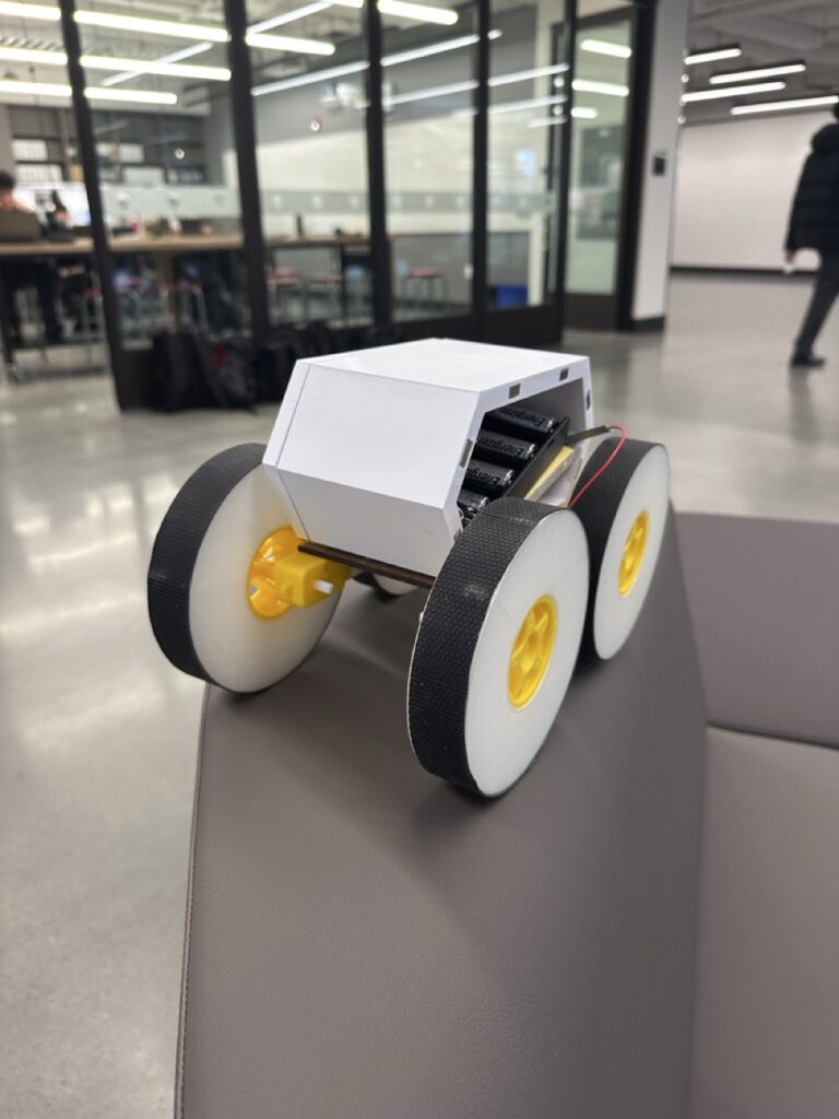
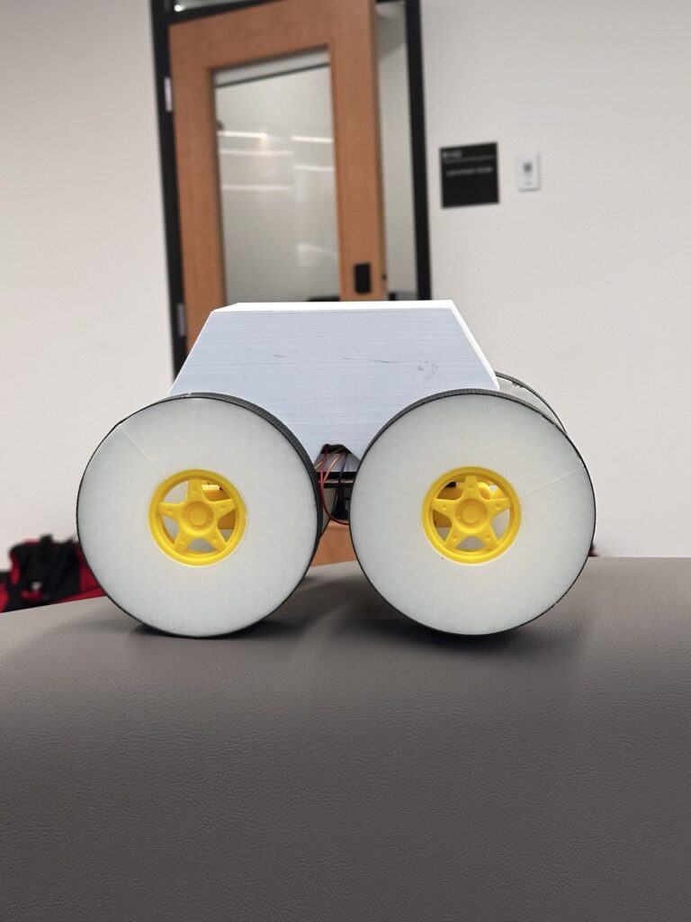
Due to time constraints, we were unable to carry out the two tests which we had originally envisioned- an incline test and a terrain test. Thus, we had to make do with what we had and we decided on only doing an incline test on our vehicle. Here are some photos of our finalized prototype that we made with Onshape:


Our original prototype had a built in suspension system (which we ended up scrapping) and a completely different set of wheels. The only part of our prototype that had almost no change was the car chassis itself. Here is our finalized vehicle:
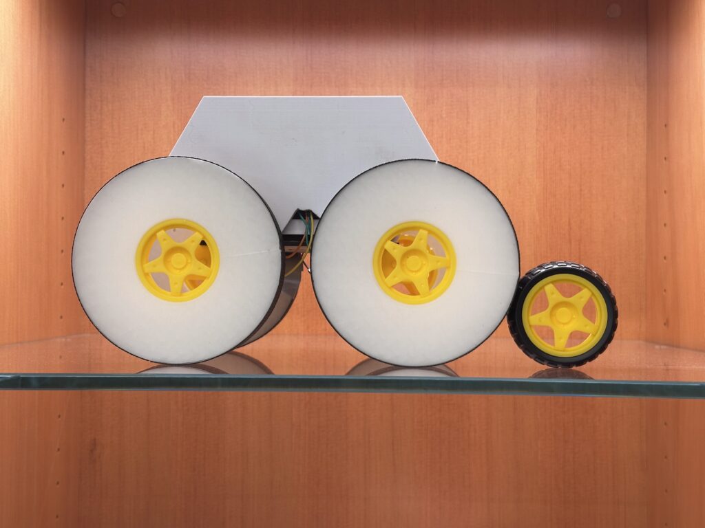
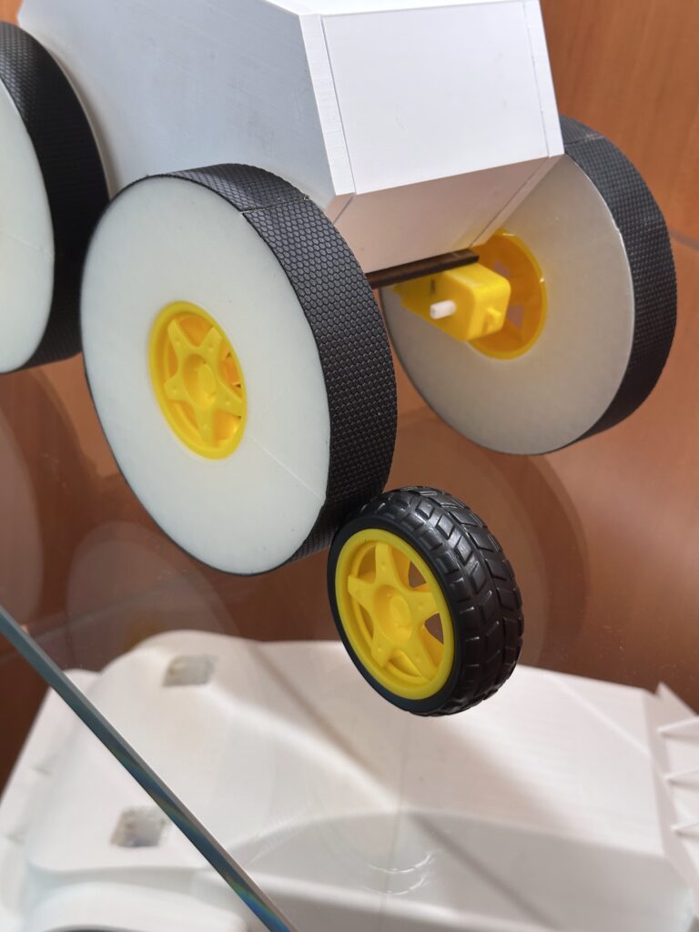
Our incline test measured how well our vehicle performed on an incline, pitting our wheels against regular DC Motor wheels, which I have displayed here:
Data:
| Incline of ramp | Big wheel time until completion (secs) | Small wheel time until completion (secs) |
| 10° | 1.5 | 1.5 |
| 15° | 1.5 | 1.5 |
| 20° | 2.0 | 1.5 |
| 25° | 2.5 | 2.0 |
| 30° | 3.0 | 2.0 |
| 35° | Failed | 3.0 |
| 40° | Failed | Failed |
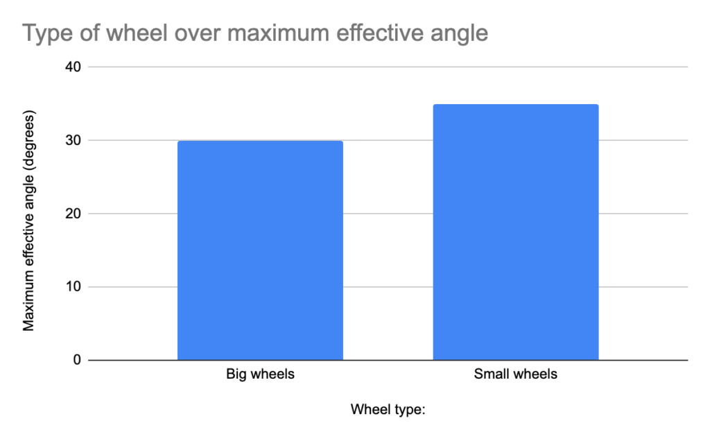
The data collected from our groups’ test shows that our wheels actually hindered the performance of our vehicle on more mountainous and steep terrain.
Analysis:
Since we were unable to collect any quantitative data on the terrain due to time constraints, we had to get creative when calculating energy efficiency. The electrical energy equation and a variation gravitational potential energy equation was the key to this.
Ein= PxT = V×I×T
Where E is the energy input in joules, V is voltage in volts, I is current in amps, and T is time in seconds, and P is power in watts.
8 AA batteries gave us a total of 12V, and our current was 0.8A, letting us solve for Ein with our time data from above.
P = 12 x 0.8 = 9.6
Ein= (9.6)(T)
| Incline (θ) | Ein (Big Wheels) (J) | Ein (Small Wheels) (J) |
| 10° | 14.4 | 14.4 |
| 15° | 14.4 | 14.4 |
| 20° | 19.2 | 14.4 |
| 25° | 24 | 19.2 |
| 30° | 28.8 | 19.2 |
| 35° | (Failed) | 28.8 |
| 40° | (Failed) | (Failed) |
As for the output, we used the classic gravitational potential energy equation with a bit of trigonometry mixed into it.
Eout = (m)(g)(h) = (m)(g)(dsinθ)
Where E is the energy output in joules, m is mass in kg, g is 9.81 in m/s2 (on Earth), and dsinθ is the distance of the incline (hypotenuse) multiplied by sin(θ)to find the height also known as h (opposite) measured in metres.
Our big wheels were 1kg, whereas the normal DC wheels were 0.8, and the length of the wooden board we tested on was 1.5m.
We can now substitute our equation into Eout = (1)(9.81)(1.5sinθ) for the big wheels and Eout = (0.8)(9.81)(1.5sinθ) for the small wheels.
Using opposite = sin(θ)/hypotenuse, we calculated for the height of the peak of the wooden board at each angle.
| Incline (θ) | Vertical Height h (m) | Eout (Big Wheels, 1kg) (J) | Eout (Small Wheels, 0.8kg) (J) |
| 10° | 0.26 | 2.55 | 2.04 |
| 15° | 0.39 | 3.83 | 3.06 |
| 20° | 0.51 | 5 | 4 |
| 25° | 0.63 | 6.18 | 4.94 |
| 30° | 0.75 | 7.36 | 5.89 |
| 35° | 0.86 | (Failed) | 6.76 |
| 40° | 0.97 | (Failed) | (Failed) |
An example of how we calculated our Eout was on the 10 degree incline for our big wheel:
Eout = (m)(g)(dsinθ) = (1)(9.81)(1.5sin10) = 2.55
Finally, to calculate our efficiency, we used the equation
Efficiency (η)=(Eout/Ein)×100%
Using the data we calculated beforehand, our group made a final graph for our data:
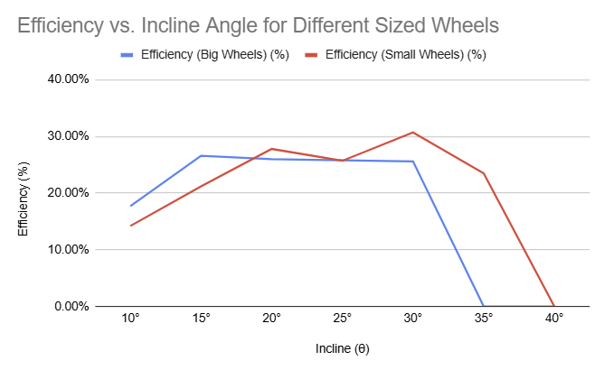
Our data displayed how our wheels had better rates of energy efficiency when tasked with lower inclines. On the other hand, the small DC motor wheels were able to prevail in the end, climbing the wooden board at a 35° angle. Our group collectively came into agreement that our wheel prototypes’ lower performance at higher angles was due to the centre of mass being too high on the vehicle, causing it to flip over on its back. The smaller wheels kept the centre of mass lower to the ground, letting the vehicle maintain its stability throughout the testing process. This issue of centre of mass was also reflected in not only just the highest angle our prototype could achieve, but the energy efficiency itself.
Conclusion/Evaluation:
Overall, our prototype was a bit of a failure as there was no significant, solidified improvement in energy efficiency when comparing our prototype wheels vs. our control (the small DC motor wheels). If we had more time to enhance the capabilities of our vehicle, we would make our wheels smaller and grippier, along with some way to use less energy or get it from a different source (e.g. solar panels). Another big issue we had was how the wheels came out of the 3d printer. The wheels were pretty firm and we wanted them to be soft, akin to a stress ball or a deflated tire. That was so we could possibly take on higher inclines and be less prone to stability issues when coming across ground debris such as rocks which are common on Ceres. Another issue was the fact that we scrapped our entire suspension system due to time constraints and it would’ve been very beneficial for our terrain if we had one (although it wouldn’t really help with the tests we conducted and we would need to create another test solely for the suspension).
Our car chassis was way too cramped and we couldn’t fit a breadboard inside properly so we had to opt-out of any complex coding on Arduino, along with the fact that we were running out of time to complete the project. Our original plan was to make a zig-zag test along the terrain to simulate a more realistic path that our vehicle would have traversed as it would need to be able to turn as well.
Realistically, if we ever do take this design to Ceres, this vehicle would probably freeze and be unable to function, not to mention the radiation due to the thin atmosphere and a bunch of other variables making our vehicle unable to function. So on top of everything I listed before, we would need to make modifications to accommodate for all of these factors, which would probably cost (on the low spectrum) a few million dollars to make. This would include (but not be limited to) multi-layer insulation for heat retention and maintenance within the vehicle, radiation shielding from materials such as polymers, protection from rocks with carbon fibre, and likely a heating system.
AI Disclosure Statement
This blog post used AI to calculate energy efficiency after plugging in test data.
Leave a Reply to mallawigan27 Cancel reply