For my third project of the 25/26 Fusion year, me and my peers were all tasked with creating a working circuit to hone our robotic skills.
What I chose to create
After much thought, brainstorming, and research, I decided to create a circuit for a fan because quite frankly, my room gets very warm (even during winter time). Of course, without requiring the necessary skills, I would have to learn step-by-step how to make this circuit.
Before starting right away…
Before attempting to create the fan, I had to learn some basics. I watched a few videos, here is one that helped me the most:
Here’s how it went…
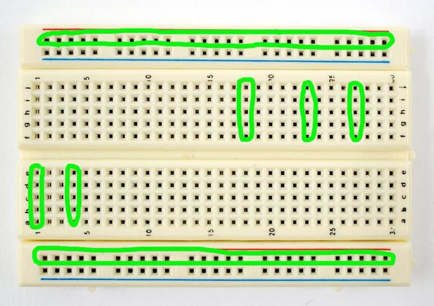
After watching the video and inspecting examples online, I got working. As Mr.Crompton had said in a previous class, there was something called a breadboard; a board used to connect electronic components (wires, resistors, capacitors, and coils) allowing for the conductivity of various experiments and projects. The breadboard is like a soccer field, and the electronic components are like the players. All the players are working together to ensure conductive success (in this case activating the fan).
All pieces used
The breadboard looks like this:
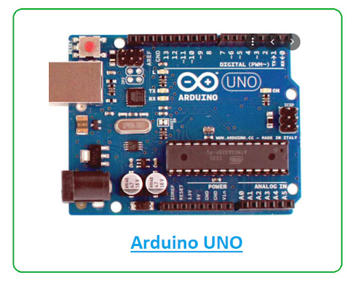
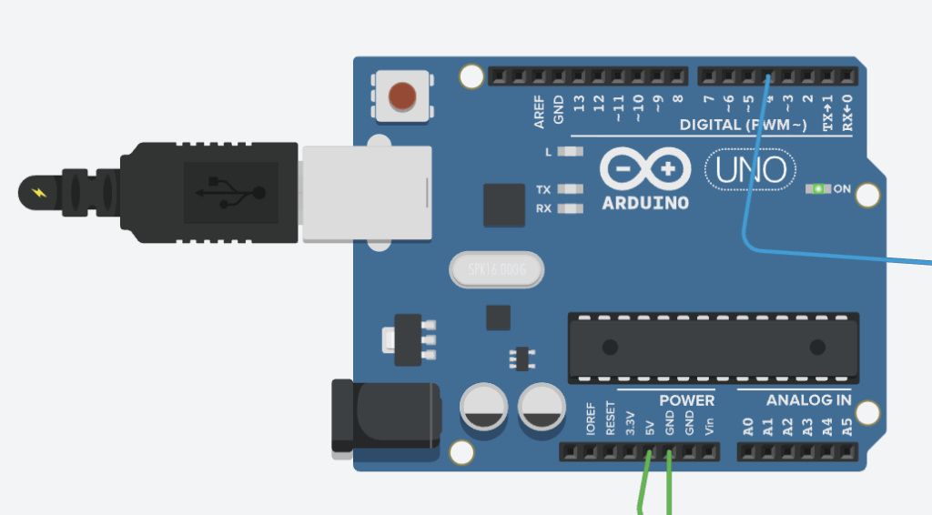
Beside the breadboard (connected via wires) is an Arduino UNO, which looks like this (will elaborate on all the pieces later on):
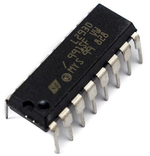
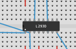
Connected to the breadboard is an L293D motor driver chip:
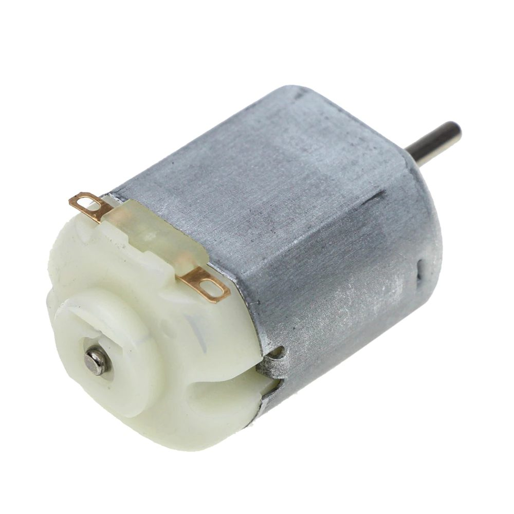
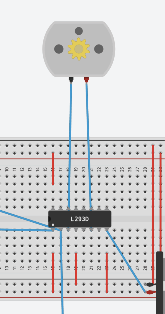
And a DC motor (the fan practically):
What does each component do?
The purpose of each piece
Breadboard:
Arduino UNO: The Arduino UNO is like the brain or head of the whole circuit. It is the component that processes all the code I write, which helps the circuit run smoother and operate more efficiently. It is also responsible for sending signals and giving directions to other components like LEDs, motors, or buzzers to perform actions. In my circuit, the Arduino sends a signal to turn my fan on or off.
L293D: The L293D’s job is controlling larger currents and voltages than the Arduino can handle directly. Its many ‘hands’ (as shown by the picture), otherwise known as its input, output, power, and enable pins, all connect wires to different places within the circuit. The wires connected to the L293D in my circuit are meant to direct electricity from the power source to my DC motor on the Arduino’s instructions.
DC Motor: The DC Motor is the component that actually uses the electricity, turning the energy into motion. The DC motor is like the finish line of a marathon and the other working components are like the coaches and guides along the track, making sure the electricity (the runner) reaches the motor safely and fairly quickly. In my circuit, the DC motor is the fan; the component that actually uses the electricity in order to serve its purpose.
TMP: The TMP is the component that measures temperature and activates the fan accordingly. For example, if my room were to become warmer, the TMP would activate other components (and wires), turning on the DC Motor (the fan).
Circuit at first glance
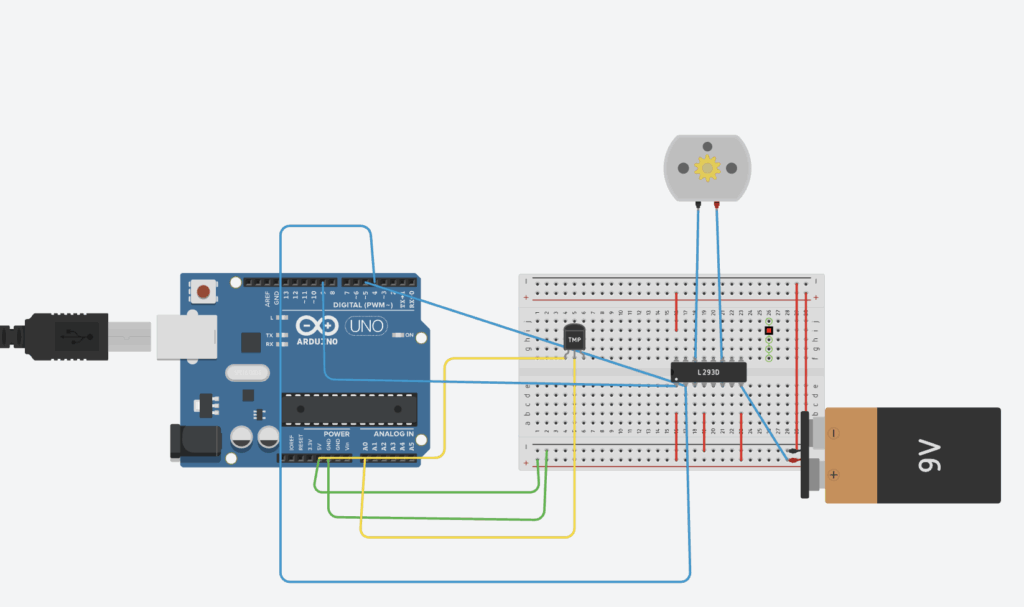
Here is what my circuit looks like (if you want to look at it and experiment yourself, here is the link): https://www.tinkercad.com/things/f53kffusogK-magnificent-lappi/editel?returnTo=https%3A%2F%2Fwww.tinkercad.com%2Fdashboard&sharecode=DcELQL0B3qmmEK7NdFA38dnDWPhRtq6y5R_xpi162y0
_ _ _ _ _ _ _ _ _ _ _ _ _ _ _ _ _ _ _ _ _ _ _ _ _ _ _ _ _ _ _ _ _ _
How does my circuit work?
As we can see, all the previously mentioned components have a role in my circuit. We can see the Arduino Uno (far left), the breadboard (middle), the L293D (attached to the middle of the breadboard), the DC Motor (top middle), and the TMP (middle left).
Additionally, all the wires (all colour coded based on different positions/purpose) can be seen attached to the different components.
Although not previously mentioned, I have added code to the circuit so everything can run without additional unnecessary parts. I will elaborate more on my code later on.
Here are the colour codes for all of the wires:
Blue = Connected to the L293D
Red = Connected within the breadboard
Green = Connected to the Arduino UNO/the DC Motor
Once I press the “Start simulation” button (top right of the circuit page), the Arduino UNO activates, plugging what I believe is a USB cable into the machine. This activates everything connected to it, which is where the wires come into play.
Here is a picture of the activated Arduino UNO:
How does my circuit work? (Part 2)
Once the Arduino is activated, it releases electricity/power through the connected wires into the components within the breadboard.
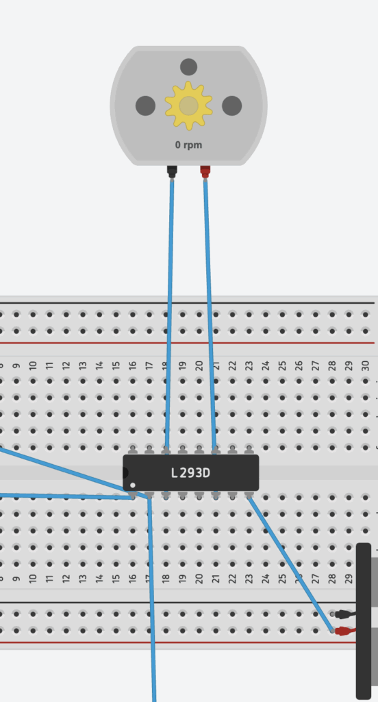
The blue wires all connect to the L293D, which was mentioned previously to be the controller of larger currents and voltages.
As you can see in the image below, the L293D possesses many pins or ‘hands’, two of which connect directly to the DC Motor and one connected to the Arduino UNO. The connected wires allow the component to direct the electricity from the power source directly to the DC motor.
Part 3
All the other seemingly ‘useless’ wires also play a major role in my circuit, as they prevent the L293D from not working or from exploding? Here’s what I mean:
Circuit with breadboard wires (first image) vs Circuit without breadboard wires (second image):
Experimenting process
I discovered this by simply experimenting and removing wires that I initially thought were useless, until realizing that they were equally important as the ones connected to the L293D. After researching the purpose of these wires, it appears that they help provide power to the different parts of my circuit, especially the L293D motor driver, which must have its own power connections to work. The red wires distribute power throughout the breadboard so that the L293D and the motor can actually receive electricity, serving a purpose I once questioned.
The TMP’s Purpose
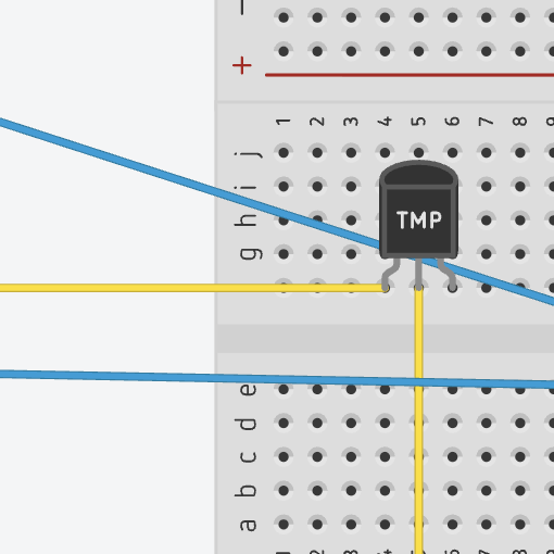
The TMP plays a major role in my circuit, as it allows the fan to only be activated when a certain temperature is present.
First, the TMP measures the temperature and sends a voltage to the Arduino Uno. Then, the Arduino Uno reads the temperature and decides when to run the DC Motor. The L293D reads the Arduino’s signal and powers the DC Motor with the 9V battery. The fans only turns on if the temperature is high enough.
Old Code
I added some code to the circuit in order to make less of a mess on the breadboard and make everything easier.
The first part of my code involves these three wires that go from the Arduino to the L293D pins:
int en1 = 5; // PWM pin → L293D Enable 1 (controls motor speed)
int in1 = 4; // Digital pin → L293D Input 1 (controls direction)
int in2 = 3; // Digital pin → L293D Input 2 (controls direction)
These match the L293D’s job:
EN1 = speed control (must be HIGH/PWM for motor to run)
IN1 + IN2 = direction control
_ _ _ _ _ _ _ _ _ _ _ _ _ _ _ _ _ _ _ _ _ _ _ _ _ _ _ _ _ _ _ _ _ _
My next part of the code tells the Arduino:
“I will be sending signals out of pins 3, 4, and 5.”
void setup() {
pinMode(en1, OUTPUT);
pinMode(in1, OUTPUT);
pinMode(in2, OUTPUT);
}
_ _ _ _ _ _ _ _ _ _ _ _ _ _ _ _ _ _ _ _ _ _ _ _ _ _ _ _ _ _ _ _ _ _
The next part of code tells the motor driver to spin the motor forward
digitalWrite(in1, HIGH);
digitalWrite(in2, LOW);
On the L293D, this combo means:
IN1 = HIGH
IN2 = LOW
_ _ _ _ _ _ _ _ _ _ _ _ _ _ _ _ _ _ _ _ _ _ _ _ _ _ _ _ _ _ _ _ _ _
Next, EN1 (the ‘enable 1’ pin on the L293D) receives a PWM signal (Pulse Width Modulation).
Range is 0–255
255 = full power
200 = medium-fast
0 = stopped
This controls how much power the L293D sends to the motor.
So here, the motor runs at speed 200.
_ _ _ _ _ _ _ _ _ _ _ _ _ _ _ _ _ _ _ _ _ _ _ _ _ _ _ _ _ _ _ _ _ _
Both of the “delay” codes don’t do much, other than basically telling the motor to keep running.
_ _ _ _ _ _ _ _ _ _ _ _ _ _ _ _ _ _ _ _ _ _ _ _ _ _ _ _ _ _ _ _ _ _
Finally, the ‘analog’ code tells the motor to stop running by cutting out power.
analogWrite(en1, 0);
Newly Implemented Code
void loop() {
int reading = analogRead(tempPin);
float voltage = reading * (5.0 / 1023.0);
float temperatureC = (voltage – 0.5) * 100.0; // TMP36 formula
Serial.print(“Temperature: “);
Serial.println(temperatureC);
if (temperatureC > 30.0) {
// Turn fan ON — clockwise direction
digitalWrite(motorPin1, HIGH);
digitalWrite(motorPin2, LOW);
analogWrite(enablePin, 255); // full speed
} else if (temperatureC < 25.0) {
// Turn fan OFF
analogWrite(enablePin, 0);
}
delay(500);
}
_ _ _ _ _ _ _ _ _ _ _ _ _ _ _ _ _ _ _ _ _ _ _ _ _ _ _ _ _ _ _ _ _ _
This code connects back to the temperature correlating to the DC motor, and how the temperature has to be high enough for the fan to activate.
BOM
Arduino UNO
Breadboard
Wires
L293D
DC Motor
AI Usage
Ai usage was minimal. Used it to help me come up with ideas and explain parts of circuits (not necessarily the ones I used in my circuit) and their purposes. Also helped me elaborate on the red wires and their purpose.
Here is a transcript of our chat(s)(on a google doc):
https://docs.google.com/document/d/1V-SQy_JlMjg0pC4guigWR4H_TfZ-3S7ViiJGEYKKPYQ/edit?tab=t.0
According to AI, every wire has a purpose which is something I learned along the way.
Thanks for listening.
Leave a Reply to macdaraw Cancel reply