Category: Uncategorized

  • Personal Project Update #1

    Problem that I am trying to solve

    Many laptops experience overheating issues that will reduce the performance of the computer and shorten the lifespan of the hardware. The market lacks an affordable automatic cooling machine for average users. However, the solution in the market right now isn’t portable to carry outside. In this case, I am building a portable automatic laptop cooling machine that people can bring out for use.

    Who am I solving this problem for

    This project is specifically for gamers and students who have a high demand on their laptop’s performance for long periods of time. These people may not have the budget to invest in a liquid cooling system that can automatically control the temperature, and they need to bring out laptops frequently.

    Research

    I gathered several sources from Amazon and other laptop cooling products.
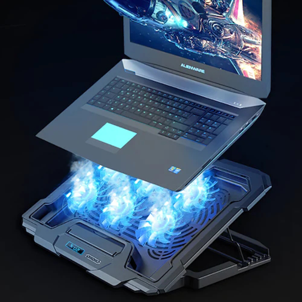
    1:

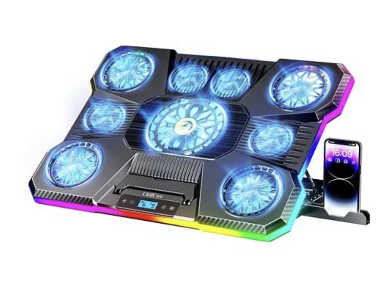
    This is an extremely common product on the market

    Strengths: This product has a strong ability to cool down the temperature of the computer, helping to prevent overheating and maintain performance. Moreover, the product is visually appealing with all the RGB lights, giving the consumers a modern and stylish look.

    Weaknesses: This product is not convenient for consumers to carry around outside due to its size. Limiting its consumability towards consumers preferring to game and work outside. User won’t be able to bring it to school or travel.

    2:

    This is another solution on the market

    Strengths: This is extremely portable and convenient for users to bring out for work, school, and travel. Moreover, considering the price, it is cheaper than the huge cooling pads with fans.

    Weaknesses: This product is not efficient compared to the huge cooling pads on the market, which will weaken the computer’s performance, especially when consumers are using a gaming laptop, which will be generating a huge amount of heat

    Solution

    My solution is to build a portable laptop cooling machine with automatic temperature control of the computer. For instance, when the computer detects that the laptop is heating up, it will start the fan and quickly cool down.

    Testing

    I am going to test it using my own gaming laptop, playing several games, and running some programs.

    Progress

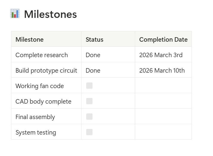
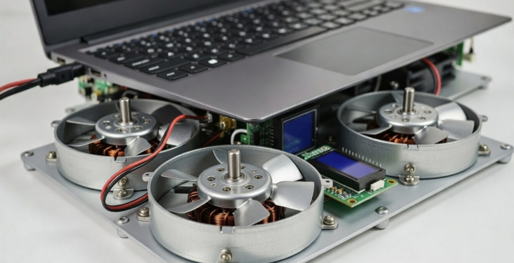
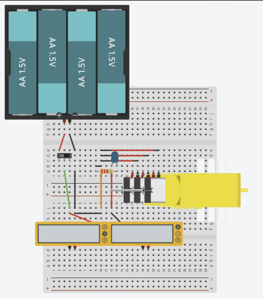
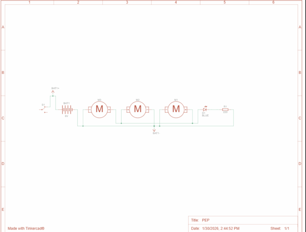
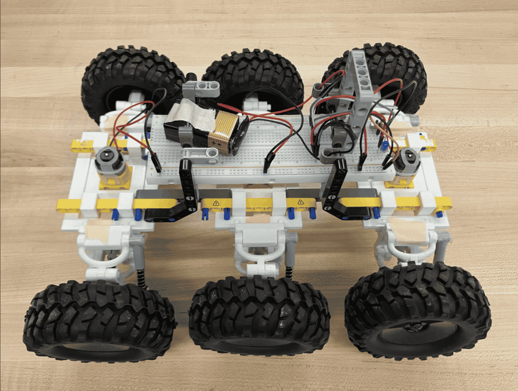
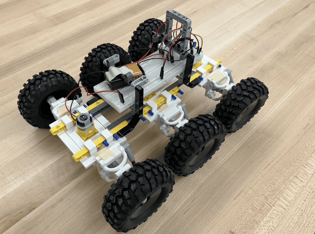
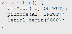
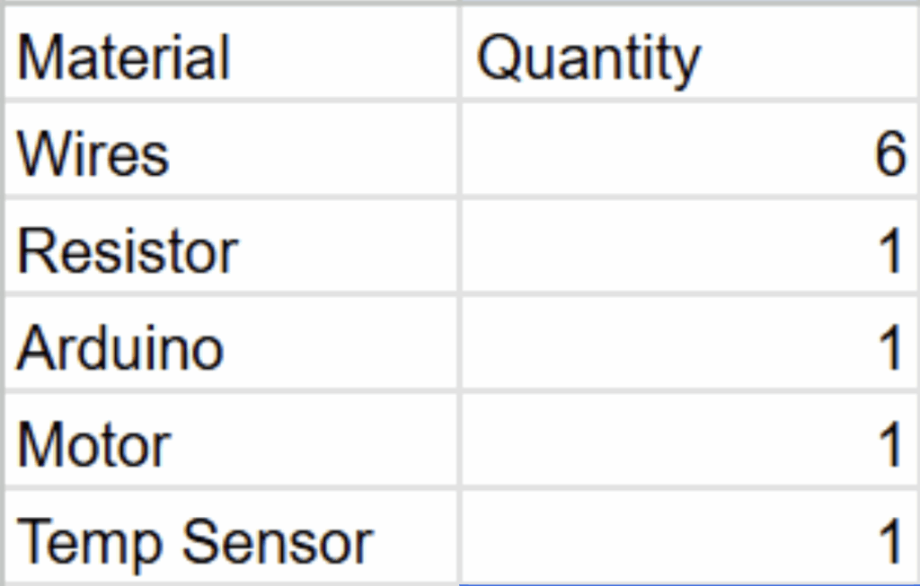
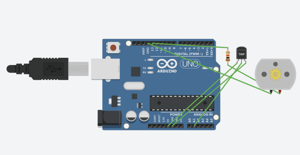
    This is the progress that I have made so far. I finished enhancing the circuit from my previous assignment, including the fan and temperature.

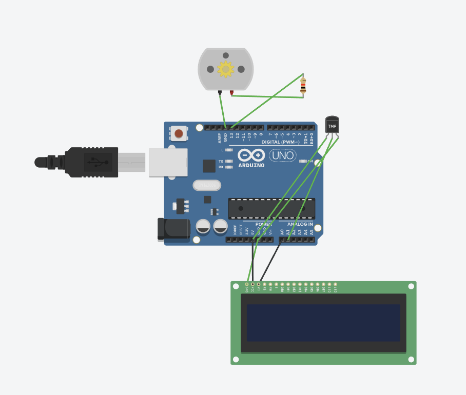
    “The prototype is functional, with the core components operating. The LCD section is not fully wired yet, but the essential setup is intact.”

    Challenges that I forsee

    I foresee a few significant challenges as I continue working on the prototype. First, coding is an area where I am still gaining experience, and writing the necessary programs for the LCD and other components will be difficult. I will need to test repeatedly to ensure it functions correctly. Second, constructing the physical body of the prototype needs to be given priority, as it requires estimation of the size of the prototype in assembly. I must plan the layout carefully, select appropriate materials, and ensure everything fits together. Despite these challenges, I see this as an opportunity to strengthen both my technical and problem-solving skills.

    What are your next steps?

    As written in the plan, my next plans are to code and to build out the physical prototype. Then, I will need to build out the body and assemble it, and ensure that it is ready for testing. Throughout this process, I will gain experience with prototyping, building, and identifying early problems before the final submission and evaluation.

    AI transparency statement

    I haven’t used AI so far in my project; however, there will be areas where I will need to use AI to support my work in the future.

  • Personal Project- First pitch

    Definition statement

    Many laptops experience overheating issues that will reduce the performance of the computer and shorten the lifespan of the hardware. The market lacks an affordable automatic cooling machine for average users.

    Who is this project for?

    This project is specifically for gamers and students who have a high demand on their laptop’s performance for long periods of time. These people may not have the budget to invest in a liquid cooling system that can automatically control the temperature.

    There value and requirements

    1: Reliablity

    2: Efficient

    3: Low cost

    Listing out the users’ requirements and needs can help me design a project that is suitable for people to use.

    Some of the ideas that I thought of

    1: Liquid cooling- it is rather expensive and complicated to achieve

    2: High voltage fan-cooling machine- It creates to much noise and contains potential safety issues.

    3: Physical heat conduction pad- It is not accessible and inefficient

    Through the comparisons between the different ideas I had, I chose to combine the fan-cooling machine and the idea of conduction to create this automatic fan cooling machine with a sensor detecting the temperature and adjusting the spinning speed of the fan. In this case, it balances efficiency, safety, and affordability.

    Potential prototype

    AI generated prototype

    Prototype description:
    It will be a circuit including 4 motors and a temperature sensor placed near the laptop. Moreover, there will be a high-voltage battery and an Arduino Uno for the control of the system.

    How it works:

    When the temperature sensor detects that the temperature increased, the fan will adjust automatically to a spin rate to cool the temperature of the laptop down. On the other hand, if the sensor detects that the temperature decreased to a normal range, then the system will decrease the spin rate of the fan to save energy and reduce noise.

    BOM (for now)

    1x Arduino UNO to process data and control the outputs

    1x Temperature sensor to detect the temperature

    1x DC motors as the cooling fans

    1x Breadboard for wiring

    Wires

    CAD for the designing of the pad

    Power source eg. Battery

    3D printed body part of the system

    Step-by-Step

    1: Research

    In this part, I will be researching other similar projects in the market and learn about how it works. Moreover, I will have an overview of what problems I might encounter and start learning how to solve them

    2: Designing, Building the circuit

    Designing and building the circuit will be the most essential part of this project. It includes writing code, connecting all the parts, and testing the accuracy.

    3: Programming

    This is a rather short period to figure out how to automatically control the spinning rate of the fan based on the temperature detected and program.

    4: Cad

    In this period, I will be creating the body part of the system based on the physical measurements of the assembled circuit, and finally printing it out

    5: Final Assembly

    I will be assembling all the parts of the circuit and body and put them together.

    6: Testing

    In this testing part, I will use my gaming laptop to operate a program that requires a strong GPU that will warm up the hardwares

    Reflection:

    Based on the planned process, it should be done by the start of May and be ready for the test. Moreover, I would have a notion page ready for the tracking of my progress throughout the whole process, from brainstorming to testing.

  • PEP Vehicle

    Problem Statement:

    Design a vehicle to consistently travel a 10 km round trip on uneven, rocky terrain, while protecting 3 astronauts and vital electronics from radiation, solar flares, and extreme surface temperatures.

    Roles:

    In the whole process, I helped with the part of brainstorming and vehicle design, and I also made contributions to the part of the CAD part, including making the suspension part and body part. The thing that I wish to learn from this process is my ability to design things. Moreover, I think that I also gained experience in dealing with unexpected scenarios

    Method/ Procedure

    Our solution to the problem statement is to focus on how to ensure that our vehicle can successfully travel 10km on rocky, uneven surfaces. We came up with an idea of adding a suspension system to cooperate with the wheels in order to have the vehicle move smoothly without being stuck on a hump. Moreover, a suspension system can allow all the wheels to stay in contact with the surface. Another key benefit that the suspension gives us is its ability to make the wheels move up and down. In this case, it helps the vehicle to cross obstacles, such as rocks, and absorbs the force created by them.

    Moreover, to ensure that our vehicle has a strong cross-country ability, we bought big wheels with good friction in order to make our vehivle to have good grip with the surface. Additionally, we also designed the vehicle holding 6 wheels to increase the grip.

    CAD

    Suspension system:

    This is the wishbone of our system.

    This is the center half. which is connected to the body part

    This the wheel attachment part, which connects with the wheels and the wishbones.

    Assembly

    This is the assembly of the whole system, which allows the wheel to travel over uneven surfaces or bumps, which will make the wheel move upward and downward. This motion transfers from the wheel to the wheel attachment part, then to the suspension spring, while the spring is compressed, and the force will be absorbed. After that, it will expand and release the force gradually to keep the vehicle balanced.

    How it works

    Driving system

    This is the joint of the universal Joint system.

    This is the part to connect the joints and connect the axle

    This is the assembly of the whole driving system. This system ensures that the axle wouldn’t bend when the wheel encounters uneven surfaces, and it is moving up and down. The universal joint allows the wheel and the axle to not be aligned perfectly. This ensures that the wheels will be moving consistently even when there is a change in allignments and it allows the wheels to be positioned at different angles to improve the stability.

    Power system

    This is the design of the circuit for the vehicle to work. First of all, when the switch is turned on, ene our target. However, because we planned to have 6 wheels and it takes 3 motorrgy flows toward the transistor, and once the transistor receives it, it allows the motor to start spinning, which powers them. Therefore, we have 2 more connected circuits to power the other 2 motors.

    Testing

    We chose to test our vehicle on gravel surfaces, since it matches the real conditions on our planet. Moreover, we also tested an incline as well since our vehicle might be facing some of the incline scenario and we want to make sure that our vehicle can have the ability to successfully cross the terrains that will potentially appear on the planet.

    Result:

    I would describe our testing process as extremely successful. We are the only group to cross the gravel surface; moreover, in our incline experiment, our vehicle successfully climbed up the incline. In our data, we recorded that our voltage is 6,15v and our current is 5.4 A. In our flat surface test, we had an average of 1.7s and an average of 1.637 s when it comes to incline.

    Gravel Surface:

    Building of the vehicle

    We focused on the other part of the problem statement, which is making the vehicle travel a 10 km round trip on rocky, uneven surfaces. We first thought of a suspension system and heavy-duty wheels. We noted that we could be taking advantage of some of the LEGO components to build the main parts. Through the brainstorm we set our first goal, which was to build the suspension system, print it out, and put it together. However, it took more time than we thought it would; we ended up missing the first test day. Through that, we made some adjustments, we reprinted the adaptors for the driving system, and reprinted the main axle. After that, Aston built the vehicle, and the parts were assembled. Unfortunately, we faced more questions, our components kept falling apart, our universal joint was too weak, our vehicle wasn’t motorized, and our wheels were too small for the rocky surfaces. To deal with these cases, we bought bigger wheels, built the circuit, reprinted the parts that were not stable, and improved our body structure. Finally, we came up with our final prototype.

    This is our vehicle with the small wheels.

    Calculation

    Energy input on gravel surface:

    E=IVT=5.4×6.15×1.07=35.5J

    Efficiency calculation on gravel surface

    Efficiency=0.65/35.5=0.01831

    Energy input on incline

    E=IVT=5.4×6.15×1.637=54.4J

    Efficiency calculation on incline

    Efficiency=0.65/54.4=0.012

    Energy output

    Energy output=0.93×9.8×0.074=0.67J

    Energy difference

    Energy difference= 54.4-35.5=18.9J

    Energy Efficiency

    Energy efficiency=0.675/18.9=3.57%

    Definition:

    In this specific project, energy is defined by how much energy the car generates when moving forward, considering the known current and voltage values. Moreover, efficiency is defined as how much distance the vehicle can travel with a specific amount of energy input.

    Analysis

    There is extra work used on the incline part, which can be shown in the data of using 0.675J, and there is an extra energy used on the incline. Moreover, regarding the efficiency, it showed that only3.57% of energy is used to lift the vehicle, and most of them are lost due to friction, gravity turning into non-useful

    processes.

    Conclusion:

    Overall, I believe that this project can be counted as successful, our vehicle passed the test that we designed for it. Moreover, we had a unique design for how to make the vehicle go. This project can be considered successful; our vehicle passed the test through uneven and rocky surfaces, which is the suspension system. During the test, our vehicle passed through the rocks and inclines smoothly; the suspension system did its job by keeping the vehicle stable and decreasing the bumps and shakes.

    Possible improvements in the future

    As mentioned above, we only focused on the second half of our problem statement. Although we did make it happen, I think that if we have more time, I would put some focus on designing the protection system for the vehicle as well. Whether it’s endurance in severe weather conditions or whether it is the protection system towards the radiation on Proxima Centauri B, I think it is worth to explore anmd come up with a plan to solve those issues. Additionally, coming back to our vehicle itself, considering the low efficiency that we calculated in the calculation part, I believe we could have thought of reducing the friction and using more efficient motors to improve the overall efficiency.

    AI transparency statement

    I used ChatGPT to support the process of our project

    https://docs.google.com/document/d/1WTE4LZiwhjcSo4YPTIlRDqXYyJOga0VarQ9-ucqL7-Y/edit?tab=t.0PT

  • PEP Assignment 1

    For this project, my group and I decided that we will be targeting our exploration towards the Proxima Centauri B, which is an exoplanet orbiting the dwarf star Proxima Centauri. When it comes to the specific reason why we are selecting these categories below

    1: Human Exploration

    Proxima Centauri B is only 4.24 light-years away from us, making it the closest potential habitable exoplanet. Moreover, it is Earth-sized and rocky, there are promising water resources on this planet, and most importantly, it is considered the most promising candidate for supporting life beyond Earth.

    2: Potential

    Proxima Centauri b has a solid surface instead of gas. Furthermore, it is located in a habitable zone from the star, also known as the “Goldilocks Zone,” where the temperature is just right for Liquid water to exist and for humans as well. It is located 7.5 million km away from its star. Although the distance between Proxima Centauri b and its star is much smaller than the distance between Earth and the Sun, considering that its star is a dwarf star that releases less energy and heat, which will make it suitable for biological activity as well

    ____________________________________________

    What Opportunities present themselves on PCb

    The most valuable opportunity that appeared on this planet is mostly exploring resources that can develop human’s technology level

    1: Resource development and Scientific investigation

    Further exploration. While exploring the planet, it is possible that we can find valuable resources. Some of them might actually adress to problems we have on Earth currently. Moreover, as a planet formed near a “Red Dwarf,” We can have some further exploration on Red dwarf stars to expand our knowledge in order to have a better understanding of the universe.

    2: Potential life out of the Solar system

    When it comes to exploring a planet, I think the point that everyone cares about is whether there is life appearing on that planet, especially when the target is Proxima Centauri b. According to the ALMA radio telescope, detecting the dust belt, and it seemed like there might be delivery of water. Furthermore, PCb is very similar to Earth in terms of size, and that gives a possibility of having a solid surface and even Oceans

    ____________________________________________

    What chllenges will I face

    1: Distance

    Distance is one of the most significant aspect of the challenge for this plan, how to bring human to a place that is 4 light years away from us

    2: Radiation

    As stated that Proxima Centauri b is located near a red dwarf star which will likely be emitting solar flares that is extremely deadly.

    3: Tidal Lock

    Due to the distance between the two stars, there might be a tidal lock scenario. This means that the planet stops spinning and only one side gets star light while the other side don’t which will cause extreme weathers.

    ____________________________________________

    How to design the vehicle

    1: Radiation shielding

    Due to the problem of radiation, a good method is to add a Radiation shield to protect the human and the mechine from the high radiation environment and ensure that all the machines will be working, I would suggest using lead and synthetic polymers to help protect the vehicle stops operating due to the strong radiation and more importantly to protect human from the strong radiation that will be likely causing serious damage towards our body.

    2: Temperature and cross- country setting

    First of all, it is extremely siginificant to have thermal material to lock the heat in from flowing out in order to keep the instruments in the vehicle work instead of collapsing in extrmeme temperatures, moreover is to keep human warm and safe from some extreme weathers. Additionally, it is definitely cruecial to design the vehicle with the speciality of cross country. Since there isn ‘t any road obviously, therefore, the condition of the surface we are moving cannot be determined. In this case, a strong, reliable system that can endure harsh roud conditions is neccessary.

    ____________________________________________

    How we know about the planet

    1:European southern observatory’s telescopes in Chile

    This is the first human telescope that actually discovered this planet and concluded that it is 4.24 light years away from us by using a radical velocity method. They also establish the conclusion that the distance between Earth and Proxima Centauri is the closest exoplanet from us. Moreover, they also identified the flares and chromospheric activity of the star and that gives the scientist a hypothesis of the possibility that an exoplanet might be orbitting it.

    2: Pale Red Dot project

    This is a project launched to prove the existence of Proxima Centauri b and they soon confirmed the theory that said that an exoplanet orbitting the Proxima Centauri b does exist by using the HARPS which is also known as the High Accuracy Radial velocity Planet Searcher which is a part of the ESO telescope.

    3 Sources

    A project determined the radius, the internal structure and indentified what kind of planet PCb is. Another project simulated how the planet will work with some variables.

    ____________________________________________

    APA format citation

    Brugger, B., Mousis, O., Deleuil, M., & Lunine, J. I. (2016). Possible internal structures and compositions of Proxima Centauri b. The Astrophysical Journal Letters, 831(2), L16. https://doi.org/10.3847/2041-8205/831/2/L16

    Cermak, A., & Cermak, A. (2025, July 30). Proxima Centauri b – NASA Science. NASA. https://science.nasa.gov/exoplanet-catalog/proxima-centauri-b/

    [email protected]. (n.d.). The Pale Red Dot campaign. ESO. https://www.eso.org/public/images/ann16002a/

    Martin, P. (2019, January 21). Planet Proxima Centauri b. exoplanet.eu. https://exoplanet.eu/catalog/proxima_centauri_b–4042/

    Noqtis. (2025, March 4). Proxima Centauri b: Earth’s nearest exoplanet neighbor. Starvium. https://starvium.com/planets/proxima-centauri-b

    Wikipedia contributors. (2025, November 13). Proxima Centauri b. Wikipedia. https://en.wikipedia.org/wiki/Proxima_Centauri_b

    Wu, Y., & Wang, Z. (2024). Progress in ionizing radiation shielding materials. Advanced Engineering Materials, 26(21). https://doi.org/10.1002/adem.202400855

    ____________________________________________

    Use of AI

    CHATGPT

  • Robotics Blog Post

    Introduction

    For this project, through some failed attempts, I gained a lot of experience with dealing with coding and wiring problems. What I did is a temperature controlled fan circuit, this means that whether the fan operates or not depends on the temperature shown on the temperature sensor

    This project simulates a scenario when we when we need an automatic temperature control of a living room. This system will be helping a lot by adjusting the temperature by opening the fan automatically

    Code

    Explanation

    This is a very cool thing that I discovered through this topic is to set a variable A and add int to say the stored integers

    These codes means that the whole thing will be running once when the Arduino starts. Moreover, I setted 13 as the output point and A1 as the input point and we ensured that the Arduino would be able to send data to my computer with adding Serial.begin

    These codes basically means that I want it to read the code from A1 fwhich is the temperature sensor data and stores it in variable A. Then, the Arduino will be sending data to my computer stored in A and pause 1 second

    This is the most essential part of the code, when the data stored in A showed that it is greater than 160( it is written as this due to the conversion) than it will set pin 13 to high which means opening the fan. However, if it is lower than 145 it will close the fan.

    Bill Of Materials

    Prototype

    How this works

    First of all, the temperature sensor will send data to the Variable stored and it will send it to the computer. After that, the data will be analyzed, and control the fan accordingly.

    Demonstration

    Summary

    This is one of the project that I really struggle with, however, with the help of Mr. Crompton I actually did it and challenged myself. All the wiring and coding are pretty complicated for me but I am glad that the final project turns out pretty well

    Use of AI

    CHATGPT

  • CAD Blog Post

    When I started thinking of this project, the first thing that I thought about was making a bottle container for any liquid. However, when I started making the cylinders, I was thinking about why not make it interesting. Therefore, I decided to make an engine, to be specific, not the whole engine with all the details, whcih might be costing months of time, I did the pumping cylinders part.

    Part 1

    This is the first part of the whole thing, it is just basically creating circles and making extrudes.

    Part 2

    This is another part using the tool of three point arc to make it symmetrical towards the original cylinder.

    Part 3

    This is the last part of the body which simply includes two cylinders and the 3 dimension shape that we made on the second part.This part is also the main rotation part of the engine that pumps the pistons up and down.

    This is the main part of the project, which is called the pistons, they are the things that goes up and down. I started this part by using the diameter of the cylinder in part 3 to create a circle. Then I created another circle slightly smaller and connected them together. Then used the extrude tool to make it 3d. Lastly using the revolve tool to make the top part.

    This is the whole thing connected together

    Another view…

    The interaction of the whole project will be including numerous ratational parts. First of all, between part 1 and part2 , there should be flexible and ratational. In this case, it can be spinning up and downto create energy. Moreover, the part in part3 that is letting the piston part hold should also be rotational in order to push the piston up. Lastly. the connection point between the part2s and part3s should also be rotational just to make sure the piston can be pushed.

    The drawing of the project

    The total materials needed:

    Revolute mate and fastened mate

    In this part I used a fastened mate in order to lock the air outlet part which is the coloured circular ring to the piston since I used different parts for them. Moreover, I used revolute mate to show how the rotational parts actually works.

    CAD url: engine | Assembly 1

    Conclusion:

    This is the first 3D model creating project, I thought I did pretty well on the logic of the whole project. However, I think it will be best if I can add more details to the pistons, or even make it more complicated such as a whole engine of a car.

  • Number game blog post

    1: As the project was announced, it actually made me quite struggle since I have nearly zero experience in Python so I have to go through how python code was made and the fundamentals.

    I started with thinking of doing something sports related like a bouncing ball code. However, It came out that the background and the ball image is hard to be crafted together. From this, I got inspired to make a number guessing game.

    ____________________________________________

    This is my Code for the project

    “欢迎使用 Colab”的副本 – Colab

    ____________________________________________

    This is the flow chart of the process

    ____________________________________________

    These are the definitions of what each code does

    1:

    This sentence is mainly telling the system that we are about to code a thing that requires random generates and define this number_guessing_game

    2:

    This sentence means we are letting the system randomly pick a number to start the game and greet the user

    3:

    These are basically the greeting sentences, and sets the attempts count

    4:

    These code are basically setting up the place for user to type in their guesses for the game and as they typed an answer, it will count as an attempt

    5:

    These codes are basically giving out hints when the user’s guess is lower or higher than the actual number

    6:

    These are the codes that calculates the attempts and show the user that they got the correct answer

    7:

    This is basically the part of how the system should do if the player input a non-number thing

    Function Definition

    These are the parts pf Function, creating a reusable code that includes the whole game in it

    Commentation

    In this project I do beleive that my code is fairly clear even though it is only a simple number guessing game , this project actually helps me learn the basics of coding like the variables, definition statements and how to make the system show words. Moreover, it is also significant as a prerequisite for future projects that will be involving coding part in it

    ____________________________________________

    The Complete AI Interaction

    AI Interactions

  • Hello world!

    Welcome to User’s blog Sites. This is your first post. Edit or delete it, then start writing!