Problem Statement:
Design a vehicle to consistently travel a 10 km round trip on uneven, rocky terrain, while protecting 3 astronauts and vital electronics from radiation, solar flares, and extreme surface temperatures.
Roles:
In the whole process, I helped with the part of brainstorming and vehicle design, and I also made contributions to the part of the CAD part, including making the suspension part and body part. The thing that I wish to learn from this process is my ability to design things. Moreover, I think that I also gained experience in dealing with unexpected scenarios
Method/ Procedure
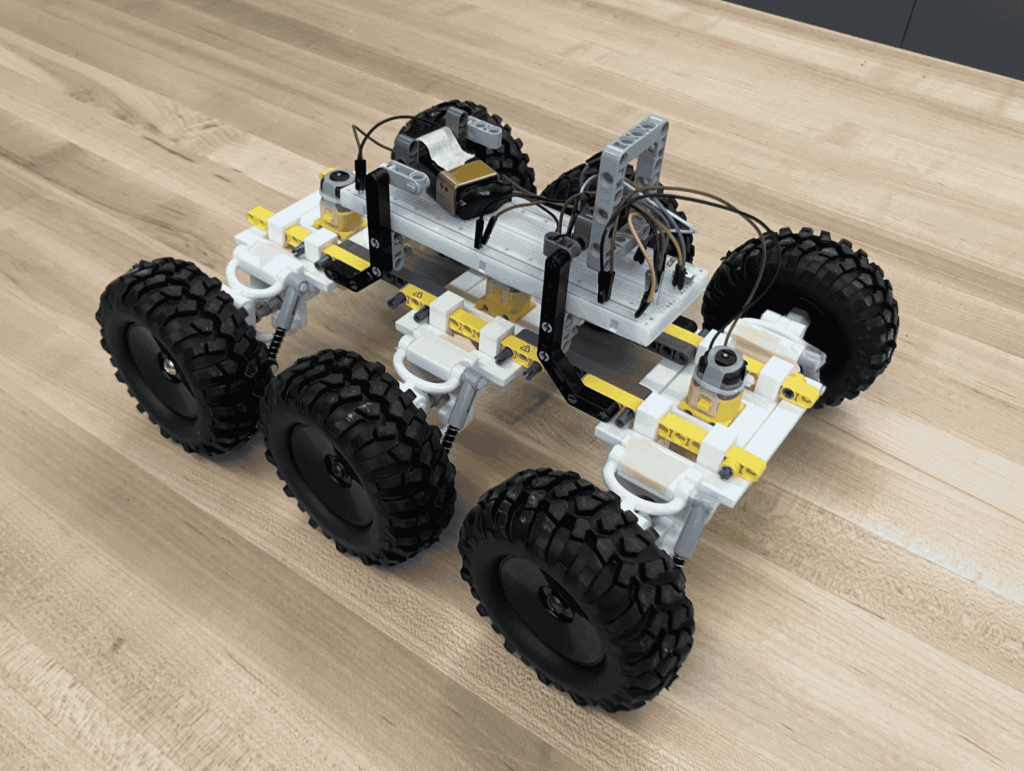
Our solution to the problem statement is to focus on how to ensure that our vehicle can successfully travel 10km on rocky, uneven surfaces. We came up with an idea of adding a suspension system to cooperate with the wheels in order to have the vehicle move smoothly without being stuck on a hump. Moreover, a suspension system can allow all the wheels to stay in contact with the surface. Another key benefit that the suspension gives us is its ability to make the wheels move up and down. In this case, it helps the vehicle to cross obstacles, such as rocks, and absorbs the force created by them.
Moreover, to ensure that our vehicle has a strong cross-country ability, we bought big wheels with good friction in order to make our vehivle to have good grip with the surface. Additionally, we also designed the vehicle holding 6 wheels to increase the grip.
CAD
Suspension system:
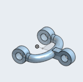
This is the wishbone of our system.
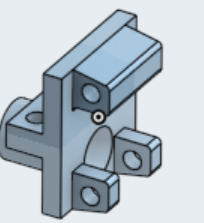
This is the center half. which is connected to the body part
This the wheel attachment part, which connects with the wheels and the wishbones.
Assembly
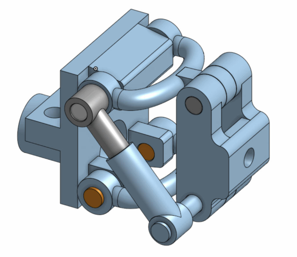
This is the assembly of the whole system, which allows the wheel to travel over uneven surfaces or bumps, which will make the wheel move upward and downward. This motion transfers from the wheel to the wheel attachment part, then to the suspension spring, while the spring is compressed, and the force will be absorbed. After that, it will expand and release the force gradually to keep the vehicle balanced.
How it works
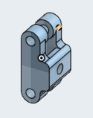
Driving system
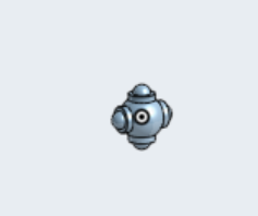
This is the joint of the universal Joint system.
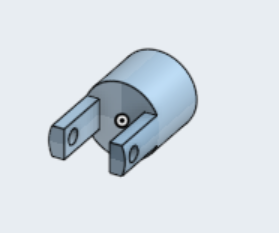
This is the part to connect the joints and connect the axle
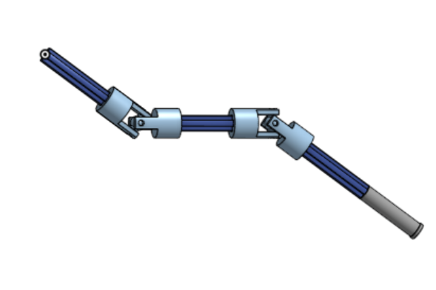
This is the assembly of the whole driving system. This system ensures that the axle wouldn’t bend when the wheel encounters uneven surfaces, and it is moving up and down. The universal joint allows the wheel and the axle to not be aligned perfectly. This ensures that the wheels will be moving consistently even when there is a change in allignments and it allows the wheels to be positioned at different angles to improve the stability.
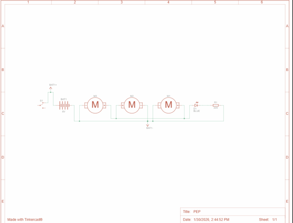
Power system
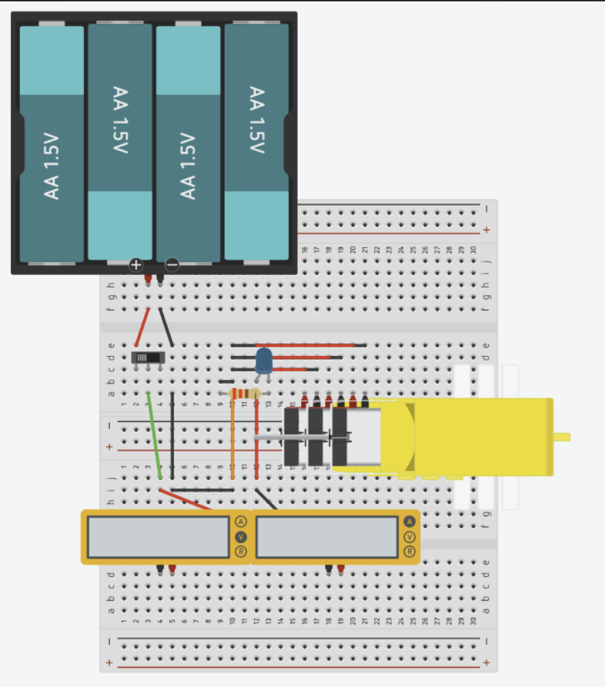
This is the design of the circuit for the vehicle to work. First of all, when the switch is turned on, ene our target. However, because we planned to have 6 wheels and it takes 3 motorrgy flows toward the transistor, and once the transistor receives it, it allows the motor to start spinning, which powers them. Therefore, we have 2 more connected circuits to power the other 2 motors.
Testing
We chose to test our vehicle on gravel surfaces, since it matches the real conditions on our planet. Moreover, we also tested an incline as well since our vehicle might be facing some of the incline scenario and we want to make sure that our vehicle can have the ability to successfully cross the terrains that will potentially appear on the planet.
Result:
I would describe our testing process as extremely successful. We are the only group to cross the gravel surface; moreover, in our incline experiment, our vehicle successfully climbed up the incline. In our data, we recorded that our voltage is 6,15v and our current is 5.4 A. In our flat surface test, we had an average of 1.7s and an average of 1.637 s when it comes to incline.
Gravel Surface:
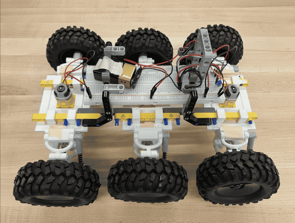
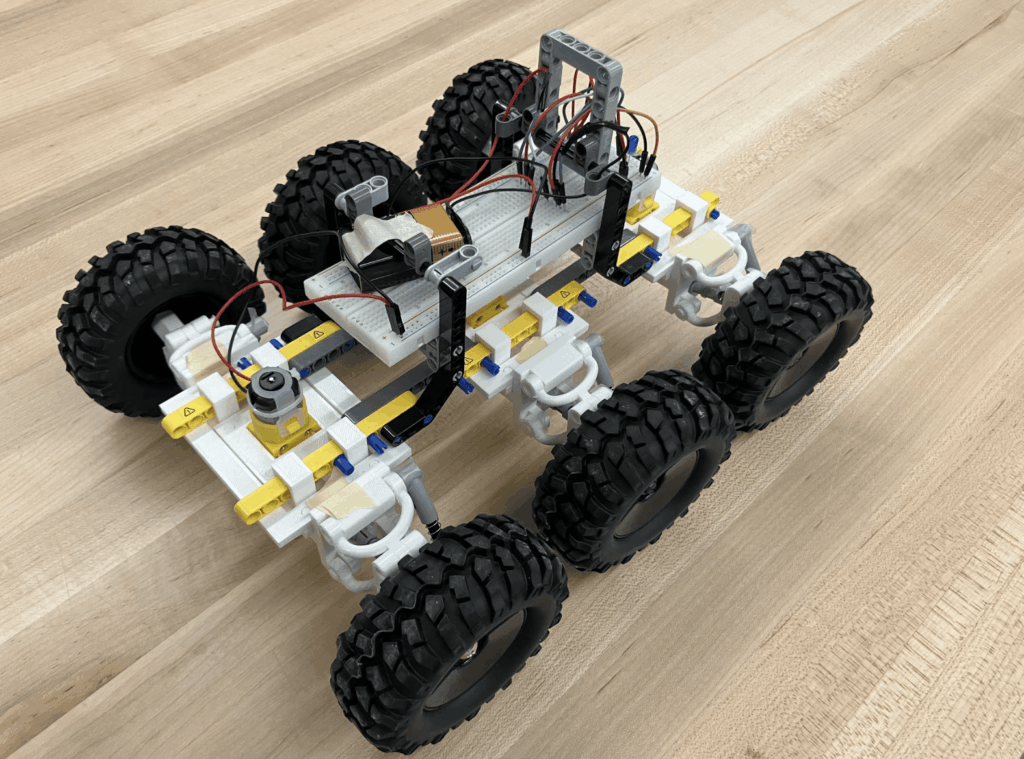
Building of the vehicle
We focused on the other part of the problem statement, which is making the vehicle travel a 10 km round trip on rocky, uneven surfaces. We first thought of a suspension system and heavy-duty wheels. We noted that we could be taking advantage of some of the LEGO components to build the main parts. Through the brainstorm we set our first goal, which was to build the suspension system, print it out, and put it together. However, it took more time than we thought it would; we ended up missing the first test day. Through that, we made some adjustments, we reprinted the adaptors for the driving system, and reprinted the main axle. After that, Aston built the vehicle, and the parts were assembled. Unfortunately, we faced more questions, our components kept falling apart, our universal joint was too weak, our vehicle wasn’t motorized, and our wheels were too small for the rocky surfaces. To deal with these cases, we bought bigger wheels, built the circuit, reprinted the parts that were not stable, and improved our body structure. Finally, we came up with our final prototype.
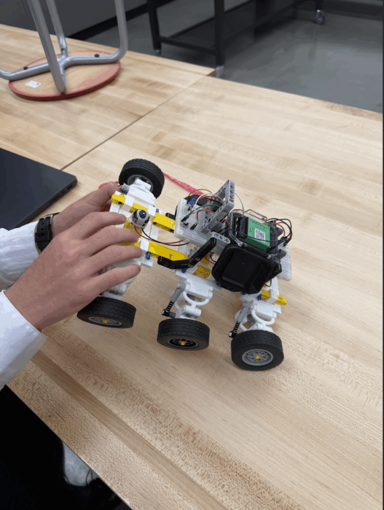
This is our vehicle with the small wheels.
Calculation
Energy input on gravel surface:

E=IVT=5.4×6.15×1.07=35.5J
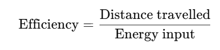
Efficiency calculation on gravel surface

Efficiency=0.65/35.5=0.01831
Energy input on incline

E=IVT=5.4×6.15×1.637=54.4J
Efficiency calculation on incline
Efficiency=0.65/54.4=0.012
Energy output
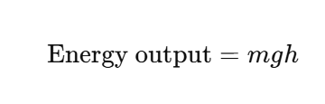
Energy output=0.93×9.8×0.074=0.67J
Energy difference
Energy difference= 54.4-35.5=18.9J
Energy Efficiency
Energy efficiency=0.675/18.9=3.57%
Definition:
In this specific project, energy is defined by how much energy the car generates when moving forward, considering the known current and voltage values. Moreover, efficiency is defined as how much distance the vehicle can travel with a specific amount of energy input.
Analysis
There is extra work used on the incline part, which can be shown in the data of using 0.675J, and there is an extra energy used on the incline. Moreover, regarding the efficiency, it showed that only3.57% of energy is used to lift the vehicle, and most of them are lost due to friction, gravity turning into non-useful
processes.

Conclusion:
Overall, I believe that this project can be counted as successful, our vehicle passed the test that we designed for it. Moreover, we had a unique design for how to make the vehicle go. This project can be considered successful; our vehicle passed the test through uneven and rocky surfaces, which is the suspension system. During the test, our vehicle passed through the rocks and inclines smoothly; the suspension system did its job by keeping the vehicle stable and decreasing the bumps and shakes.
Possible improvements in the future
As mentioned above, we only focused on the second half of our problem statement. Although we did make it happen, I think that if we have more time, I would put some focus on designing the protection system for the vehicle as well. Whether it’s endurance in severe weather conditions or whether it is the protection system towards the radiation on Proxima Centauri B, I think it is worth to explore anmd come up with a plan to solve those issues. Additionally, coming back to our vehicle itself, considering the low efficiency that we calculated in the calculation part, I believe we could have thought of reducing the friction and using more efficient motors to improve the overall efficiency.

AI transparency statement
I used ChatGPT to support the process of our project
https://docs.google.com/document/d/1WTE4LZiwhjcSo4YPTIlRDqXYyJOga0VarQ9-ucqL7-Y/edit?tab=t.0PT
Leave a Reply to Ms. Holmen Cancel reply