Definition Statement/Problem and Audience(Not changed):
Beginner and intermediate racing drivers often struggle to learn effective driving lines for their specific cars because most learning occurs on real racetracks, where practice is expensive, time-limited, and sometimes risky.
The main intended audience for this project is to beginner and intermediate drivers who may:
– Do not have professional coaching
– Cannot afford frequent track days/Don’t have time
– Interested to improve their racing in different tracks
Solution to the problem(for more details navigate to the initial pitch post)
Racing line simulation project. A simulation that is able to take in BASIC INFORMATION of a car and a track and generate the MOST OPTIMIZED line to the track of that car.
Research done
The most important and key part of the project is the physics and input I would need to have from the User to generate my output. From the research done, the simulation would require: CAR VARIABLES:
Vehicle Mass (kg)
Grip of the car
Engine Power (hp)
Maximun breaking force
Aerodynamic downforce (if possible but is optional)
TRACK VARIABLES
Corner Radius (m)
Corner Angle
Straight lengths (m)
Some of these variables would require calculation to get and also difficult to understand especially for beginner drivers for example the maximum breaking force and the grip of the car. For these specific variables, instead of inserting a value for this requirement, the plan is to make the user insert multiple other statistics about the car to calculate these variables.
Calculation and Physics
There are multiple physics models required for the calculation
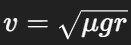
1. Cornering speeds (grip Limit of the car)
V = maximum speed through the corner (m/s) μ = tire grip coefficient g = gravity (9.81 m/s²) r = corner radius (m)
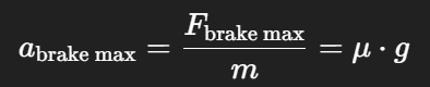
2. Maximum breaking force
F = maximum braking force (N) μ = tire-road friction coefficient m = mass of the car (kg) g = gravity (9.81 m/s²)
3. Maximum breaking acceleration
a = maximum possible braking acceleration (m/s²) μ = coefficient of friction between tires and road g = gravity (9.81 m/s²)
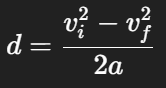
4. Braking Distance
d = distance needed to slow down(m) vi = initial speed before braking (m/s) vf = target vorner speed (m/s) a = braking acceleration(m/s²)
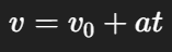
5. Acceleration
V = velocity after time t (m/s) v0 = initial velocity (m/s) a = acceleration (m/s²) t = time (s)
6. Distance while accelerating
s = distance traveled while accelerating (m) v0 = initial speed (m/s) a = acceleration (m/s²) t = time (s)
Challenges
The main challenges of this process if the amount and difficulty of the coding required to do all of the calculations and physics. One of the different takes that may influence the prjects could be implimenting machine learning into the simulation. Machine learning would be more efficient and probrably less difficult to accomplish.
Future steps
Due to the perspective of using machine learning in this project, more research would have to be conducted about AI in order for the project to be continued
Beginner and intermediate racing drivers often struggle to learn effective driving lines for their specific cars because most learning occurs on real racetracks, where practice is expensive, time-limited, and sometimes risky.
Audience
The main intended audience for this project is to beginner and intermediate drivers who may: – Do not have professional coaching – Cannot afford frequent track days/Don’t have time – Interested to improve their racing in different tracks
Idea list(Multiple different solutions)
Racing Plugin/Mod
Race Analyzer(Review not live)
Racing Line Calculator/Display
Racing Plugin/Mod
This idea was to create a plugin on an existing racing simulator that is able to support the driver while driving. It may create visual to indicate acceleration/decceleration points and also a racing line that will change live depending on the car’s current scenario.
Race Analyzer
The idea of the race analyzer is to make drivers able to visually see their race line/mistake and what could have been done better.
Racing Line calculator/Display
The idea was to create a software that can generate a 2d visual of a racing line on a designated track. The difference of this software and others is that this calculator created the most optimal line using data provided by the audience instead of the “perfect” line.
Chosen Idea – Racing Line Calculator/Display
The prototype will consist of a simplified but fully functional two dimensional racing line simulation software displayed from a bird’s eye perspective. The track layout will be clearly illustrated, and a moving point will represent the vehicle as it progresses through a full lap. Sections of the racing line will be colour coded to indicate vehicle behaviour(accelerate/brake), with green representing acceleration zones and red representing braking zones. This visual is intended to make changes in speed and driving strategy immediately understandable to the audience of this project. The prototype will include preset vehicles or an audience input bar to create/illustrate their vehicle by inputting basic data of their car, such as power, max speed, largest turn angle, and several others that may be required. The prototype will also include presets of tracks. The audience will be able to compare how different vehicles generate different braking points, apex positions, and cornering strategies on the same circuit.
A key feature of the prototype will be its interactive/educating component. The audience will be able to click on specific sections of the racing line/output, prompting a detailed explanation the reasoning behind the racing line in the section. For example, the system may explain why a late apex is selected to prioritize exit speed, why an earlier braking point is required for a higher powered vehicle, or how a lower powered car may carry more speed through a corner. This interactive element ensures that the prototype functions not only as a simulation tool but also as an educational platform that communicates the reasoning behind racing line decisions.
The goal of this project is to create a vehicle prototype that can test a prototype in an environment as close as possible to hat was stated in a definition statement created upon a chosen planet.
Definition statement
The vehicle need to be able to operate and traverse in cold underwater temperatures of −201.67 °C, keep stable in high pressure conditions, and stay energy efficient so the vehicle is able to travel at least 10 km at one filling of energy while not leaving a detrimental impact on the planet for future missions.
Due to practical limitations, the project focused on constructing and testing a scaled prototype in a controlled environment. The primary purpose of the test was to evaluate whether the vehicle could maintain proper orientation in water, manage buoyancy, and demonstrate propulsion. The test was also used to identify design limitations that would inform future improvements before attempting more complex operating conditions.
Method
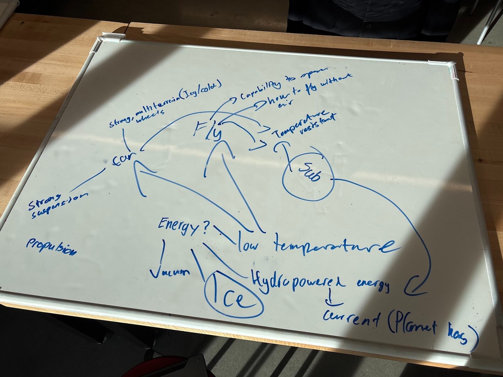
The project initiated when the team made the plan of creating a submarine prototype. A board with ideas were listed and it was later decided that a submarine would be the vehicle suitable for the planet that was chosen. Multiple precautions were also listed so these situations could be avoided. Unfortunately, buoyancy was not listed and did become a big problem factor in the first test.
Design
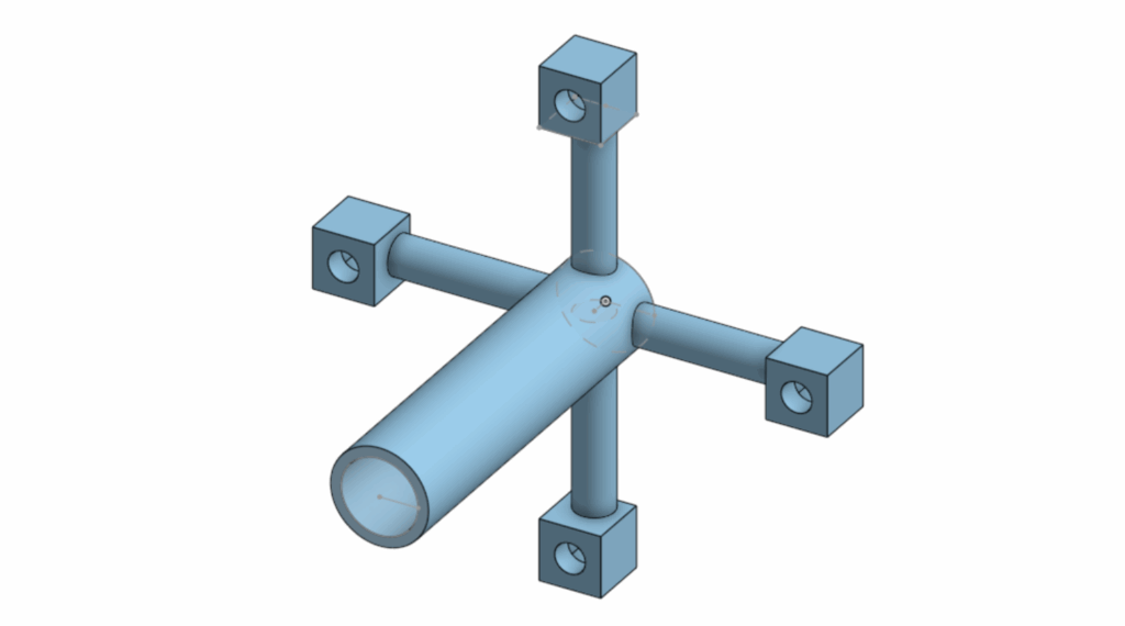
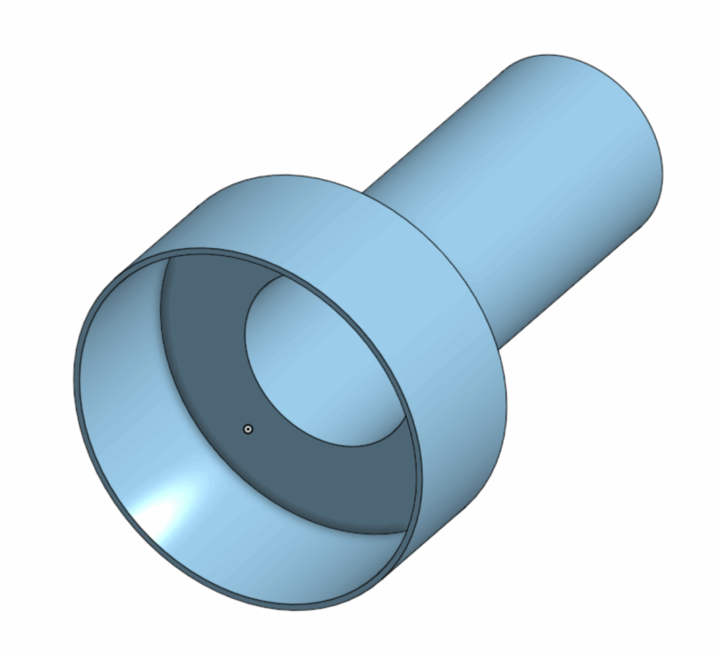
The first CAD design was created. The plan was to have the motor and battery completey sealed inside the submarine, the motor propels a propeller shaped module from the inside with magnets stuck to the module. Then a similar shaped module with propeller fans is on the otherside of the same wall with magnets in so the magnets would stick together in sync to propel the vehicle design. Due to a number of new changes there were not any saved photos of the first CAD design. The two photos listed below are the propeller modules.
The propeller module on the outside is also designed differently because the circular shape stuck to the wall would decrease the most amount of resistance while spinning in water so the actually propeller fan would push the submarine forward.
A watertight body was also created named Body V1 (version 1 – there were not any photos for this body), it is shaped a cylindar with 2 opennings 2 lids(second photo under NEW DESIGN section) were created to cover. There was also a motor holder to keep the motor up parallel to the cylinder. The plan was to put the battery and motor connected inside after attaching the module. Next, close the lids and then put the outer propelling module on the wall(one of the lids). After the lids go in the submarine is sealed with water resistant tape to watertight the submarine.
Test V1
In the actual test, the motor was not powerful enough to battle the friction between the modules and the lid which caused it to stop spinning. Instead, a watertight test was more appropraite since it could give some information needed and demonstrate progress. The results of the test stated that the vehicle was watertight, but unfortunately the buoyancy issue was not considered and the submarine was not able to submerge under water.
From the results of the test, a conclusion was made to stick with the original propelling plan but requiring a stronger(torque) motor. A shell was also designed to hold water to battle the buoyancy in the water so the submarine could submerge and travel under water. If the buoyancy issue is still unsolved extra weights would be applied to the vehicle.
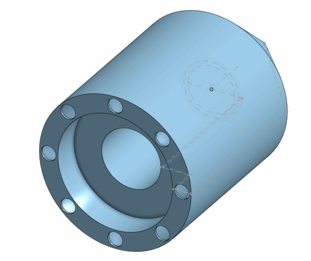
New design
The 3 photos above are the 3 main parts of the design. The first photo is the new body of the submarine. The body was no longer a shape of a cylinder, the design achieved taking away as much area for air as possible so the shell is not required to be really large. The second photo is the lid, the thickness of the wall was also minimized for better magnetic reactions between the magnets while still being watertight. The last photo is the shell, there are 8 holes designed around the side for water to flow in to counter the buoyancy. The larger hole in the middle was for the vahicle body to fit perfectly in. Water resistant tape is also added in the inside of the body to make sure the design was as watertight as possible.
The Final Test
When the test initiated, the method of making the motor spin inside the body was to place the motor into the body while the motor was running. The procedure was to open the lid, place the battery and the motor with the motor centering module on into the body while the motor was spinning, then close the lid as it also pushed the motor to a designated distance inside the body. After the lid is closed, water resistant tape was placed around the lid so that no water was able to get into the body. When the tape was on the last step was to align the magnets of the outer propeller with the inside module. The major problem was that the motor was spinning at a high speed meaning that the magnets were not able to stick together without trying to sync the magnet from the outside as well(a good reference to this scenario is a scene in the movie “Interstellar” by Christopher Nolan where the protagonists space ship had to rotate and sync with the larger ship so they can connect and travel further/survive). Methods were tried to sync the magnets onto the wall of the lid, for example humanly spinning the module at a speed but was not fast enough to sync with the rotation of the inside module causing this method to fail. Another method was also conducted which was to let the magnets sync on the lid before the motor was placed in the body humanly, but the hole fore the motor was too deep and the module rotating at high speeds was hitting the fingers of members who were trying to place the motor in. Multiple other methods were tried until the battery inside the body died and ran out meaning that the vehicle was not able to move.
Even thought the vehicle was unable to demonstrate movement, a buoyancy test was still performed on the vehicle afterwards. The results were that before extra weights added the submarine was able to submerge deeper than the first test due the the new shell design, but around a fifth of the shell was still unsubmerged. After adding weights to the vehicle, the submarine was able to submerge underwater and maintain the position and pointing direciton the vehicle was designed to(sideways in water).
Data
Unfortunately the test “failed” because the basic requirements for the prototype was not met. The vehicle was not able to move also meaning that the energy efficiency of the vehicle is 0%. The input energy was a 9V power source of a battery.
Analysis
Even though some data was retrieved, the important data of speed and distance was missing. Assumptions of these data had to be made for the analysis. The motor was strong but would have had to battle friction in the water so it may slow down. The fans of on the propeller were not angled aggressively so the speed would not be too fast. The shell was designed to be fluid dynamic. So the speed was estimated to be around 1m per second. The distance is estimated to the distance of the testing area in the pool. The distance of the pool is 15-20m
Using these assumptions, the energy efficiency was able to be calculated. With an input voltage of 9 V. AI was used to estimate the current and gemini provided data of 0.2-0.6 amps on a light motor, the system power was calculated to be 9 W. Assuming an estimated speed of 1 m/s and an expected travel distance of 15–20 m, the total operating time would be approximately 15–20 s. This results in an estimated electrical energy input of 135–180 J. Due to energy losses from water resistance, internal friction, and inefficiencies in the motor, only a fraction of this energy would be converted into useful mechanical motion. The energy efficiency is calculated to be 38.5%, the available mechanical energy would be in the range of 20–27 J. This analysis suggests that while the theoretical energy supply may have been sufficient for short-distance movement, inefficiencies in propulsion would cause a lack of forward motion/speed.
                                                         25J
Energy Efficiency = ------------------------
                                                9V x 0.4A x 18s
                                                  25
                                        = ------------
                                                 64.8
                                        = 38.5%
Conclusion
In conclusion, the vehicle prototype was not able to move, but through estimation of data the important information was retrieved. The design could have been improved in multiple ways. The vehicle could have been designed to propel in a different method. The vehicle could have also be design way better in a way so that buoyancy would not be an issue.
The assignment is for students to get into groups and choose planets that have potential in humans surviving through research. After choosing the planet, identify the challenges and opportunities so we are better fit for our design prompt given after this assignment. The Planet my group chose/coin flipped for was Enceladus.
Why Enceladus
Personally, my number one reason is because there is water on the moon. Despite its small area, the surface is completely frozen with ice and after research, information showed that there was liquid water under the frozen surface. It is also in the solar system so it would generally be easier to research about.
Basic information
Enceladus is a small icy moon of Saturn, about 500 kilometers wide, with a very bright and frozen surface. It is extremely cold, but beneath its ice is an ocean of liquid water. The south pole releases large plumes of water vapor and ice into space. These features make Enceladus a promising planet for potential design prompts for human survival.
Opportunities vs. Challenges
Eceladus presents multiple major opportunities for planetary exploration. The presence of water vapour, plumes, and heat escaping from the south pole suggests that there are oceans beneath the icy crust. The planet is also physically inside the solar system making it easy to reach and get to.
On the other hand, there are also several challenges on surviving on this planet. The surface of the planet is extremely cold and the low gravity would make landing significantly more difficult. The moon itself is also tidally locked to Saturn which means that the same face of the planet would always be facing Saturn(For example: If Earth was Tidally locked to the sun one side of the world will always be dark and one side will always be in daylight). There is also harsh radiation since there is not an atmosphere like earth on the moon, so advanced technology would be required to be on the planet.
What implications might there be for vehicle design?
Due to the moon’s special environment. The machine would have to be able to withstand cold temperatures, be able to manoeuvre on uneven terrain, and be able to be operated in low gravity. In this condition a flying probe would be more ideal than a landing vehicle.
How do we know what we know about your planet?
Human’s knowledge of Enceladus comes from the Cassini spacecraft, which studied Saturn and its moons from 2004 to 2017.Cassini’s instruments, including the Composite Infrared Spectrometer(measures radiation), Cosmic Dust Analyzer(detects dust particles that are really small), and Imaging Science Subsystem(digital camera), collected thermal measurements(temperature), particle samples, and high-resolution images. These devices detected heat at the south pole, measured the chemical makeup of the plumes, and mapped surface fractures. The data revealed water vapor, salts, organic molecules, and continuous geological activity.
This is an assignment to make students demonstate abilities to do circuit building and arduino programming. If we never did robotics before it would be an assignment to also demonstrate their learning process with either AI or other sources. Arduino is a programming language commonly seen in breadboard robot circuits.
I personally would be using Tinkercad to do my virtual schematic.
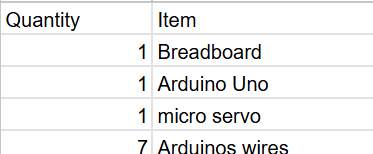
The assignment would require a circuit schematic, BOM(Bill of materials), and Code. Originally there was supposed to be a video record of the physical prototype, but due to the limited amount of Arduino Unos(mandatory for a project) and the bugs with mac computers inputting code into the Unos the physical prototype became optional.
Circuit schematic
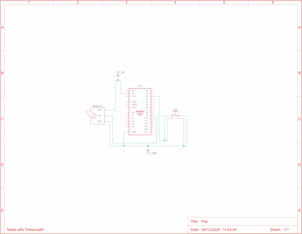
This is a really simple fan. To keep the code simple I used a positional servo but what it basically does is that once the button is clicked the servo spins once(in a positional servo that means 180).
Special thanks to Tiger Wei for helping me with some basics for example ground connects to ground in the wiring and power goes to 5V. And if multiple is needed I can go connect ground to – on the breadboard so the whole lane of – can be plugged for ground. Same for Power.
In here the signal pin on the continuous micro servo is connected to Digital pin 9 on the uno, and ground is connected to ground, power is connected to 5V on the breadboard.
Video
BOM
Code
#include <Servo.h>

const int buttonPin = 2;
const int servoPin = 9;

Servo fan;

const int positionA = 10;
const int positionB = 170;

int currentPosition = positionA;
int lastButtonState = HIGH;

void setup() {
  Serial.begin(9600);

  fan.attach(servoPin);
  pinMode(buttonPin, INPUT_PULLUP);

  fan.write(currentPosition);
}

void loop() {
  int currentButtonState = digitalRead(buttonPin);

  if (currentButtonState == LOW && lastButtonState == HIGH) {

    if (currentPosition == positionA) {
      currentPosition = positionB;
    } else {
      currentPosition = positionA;
    }

    fan.write(currentPosition);

    delay(50);
  }

  Serial.print("Button State: ");
  Serial.println(currentButtonState);

  lastButtonState = currentButtonState;
}
This is the complete code, it functions in a way so that when the button is pressed it rotates.
#include <Servo.h>
This tells the Arduino to load the Servo library, which contains all the code needed to control a servo motor. This is like import in Python.
const int buttonPin = 2;
const int servoPin = 9;
These lines create constant variables that define the hardware connections. buttonPin is set to 2, meaning the button’s signal wire is connected to Arduino Pin 2. servoPin is set to 9, meaning the servo’s signal wire is connected to Arduino Pin 9.
Servo fan;
This creates a servo object named fan. The word Servo tells Arduino what type of object it is. The word fan is the name you chose for this servo controller.
const int positionA = 10;
const int positionB = 170;
These lines define the two target angles for the servo. positionA is 10 degrees, and positionB is 170 degrees. The servo will toggle between these two fixed points.
int currentPosition = positionA;
int lastButtonState = HIGH;
These are state variables. currentPosition stores the servo’s current angle (starting at 10 degrees). lastButtonState tracks the button’s state from the previous check, and is initialized to HIGH because the pin will be high when the button is not pressed (due to INPUT_PULLUP).
When the Arduino starts, the setup() section runs one time to prepare everything. Inside it, Serial.begin(9600); starts communication for debugging.The servo is connected to Pin 9 using fan.attach(servoPin).pinMode(buttonPin, INPUT_PULLUP); sets Pin 2 to input mode and activates the internal pull-up resistor. This ensures the button pin is reliably high until the button is pressed (connecting the pin to ground).fan.write(currentPosition); moves the servo to its initial position of 10 degrees.
The loop() section runs continuously, checking the button and controlling the servo, int currentButtonState = digitalRead(buttonPin); reads the current status of the button (which will be LOW when pressed).The key condition if (currentButtonState == LOW && lastButtonState == HIGH) checks if the button is currently pressed (LOW) but was previously unpressed (HIGH). This ensures the action only triggers once for a single press.If the condition is met, the nested if/else block runs, it checks the currentPosition and flips the target between positionA (10 degrees) and positionB (170 degrees).fan.write(currentPosition), commands the servo to move to the new position.delay(50), pauses the sketch briefly to debounce the button press, ensuring electrical noise doesn’t cause false triggers.Finally, Serial.print displays the button status for debugging, and lastButtonState = currentButtonState; stores the current state for comparison in the next loop.
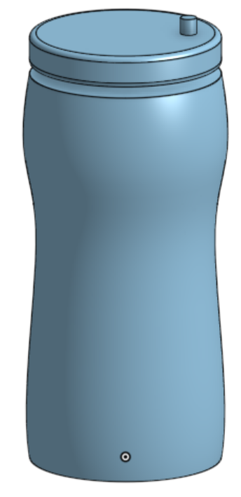
In this Fusion assignment I was assigned to do something not that complicated in CAD. I decided to do a water bottle brcause it was really easy and can show a decent amount of basic skill in CAD.
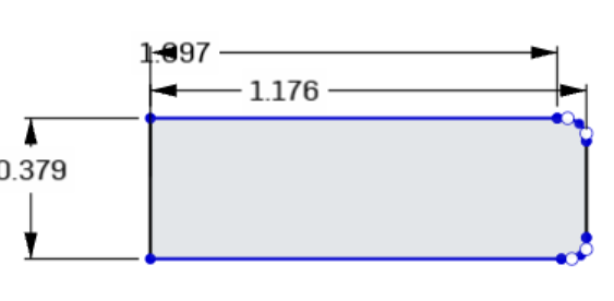
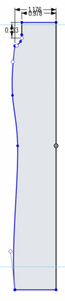
Sketching
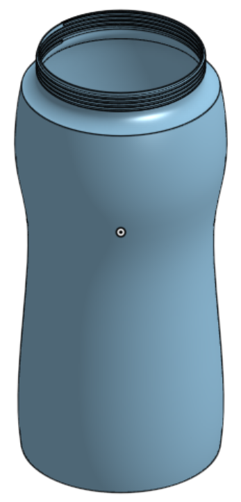
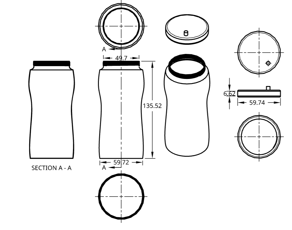
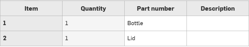
The first step was to do a sketch of the bottle. The bottle is in two parts, the first part is the actual bottle and the second bart is the lid. I made a sketch of half of it not really regarding the sizes.
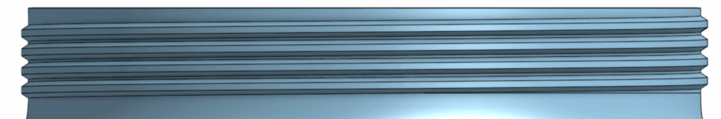
Extruding
Then I use the revolve tool to make the bottle shape. After that I had to worry about making a way the lit and bottle can fit together. So I started by using the helix tool and make a new sketch then use the sweep tool to create screw like teeths on the bottle.
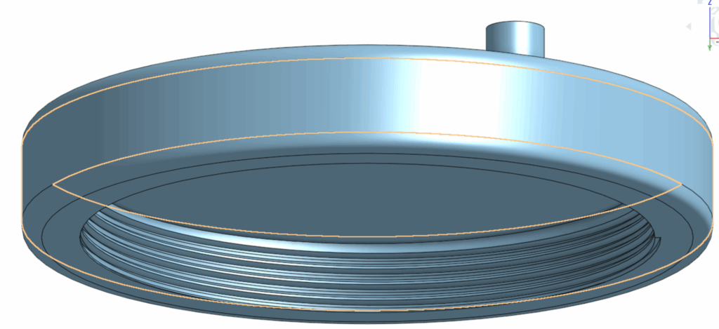
I did the same on the Lid but with the sweep I made it remove so it can perfectly fit onto the bottle. after making a hole that is the right size. in the cap I used a sketch and used the center point circle tool to make a circle then used the extrude tool to remove a hole through the original design.
For the cap you may have noticed a small cylinder on top of it, it was mainly used as a point to recognize if I did my assembly right in the future.
After these steps I still had to make a hole in the bottle. This time differently I used the shell tool because it was easy and also because the irregular shape of the bottle.
Assembly
The Last step was to do the assembling. First I created a fastened mate on the bottle to the origin point. After that I put a cylindrical mate on the cap to the bottle. Last I made used the screw motion tool to make the Lid act like a screw so it can go on the bottle as I designed it to. Now to explain why the cylinder on top of the Lid is added, the reason for that is because it is easy to see if the screw motion actually works because it it really hard to tell if the Lid is rotating in a circular motion without adding anything.
This is the first assignment of the fusion course. We as students are assigned to work with AI to create a full stack block of code in python with AI without the AI directly giving you the code. A flowchart was also requested to show my thinking process through creating the code.
Definition of some words
Python: Python is a basic coding language that is able to create and proccess functions to run what you tell a computer to do, for example if you want to let it return “Hello World”. You can simply type this into your coding application(pycharm or other):
print(“Hello World”)
Flowcharts: Flowcharts are basically a mind map that shows your thought process before you create your code. In my case it also constructs my questions I ask to Google gemini in order for it to help me.
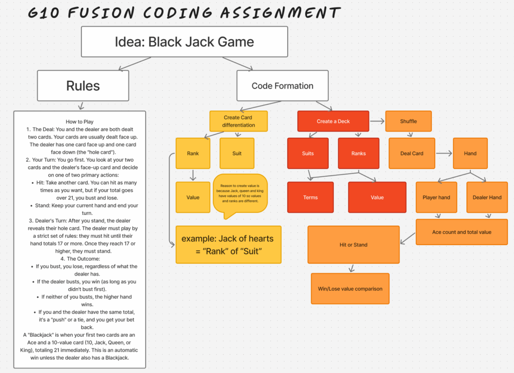
My Flowchart
I started with a flowchart to plan out how I am going to ask Gemini the questions and also how my code is going to be constructed.
In my flowchart there are 3 big parts, the first part is defining the attributes a card, my plan was to use suits and ranks for cards and later on define the value of each rank. The second part is when I created the Deck with suits and ranks. in my flowchart I connected suits to term since there are only 4 different suits and they do not interfere with the outcome, but ranks on the other hand do, so I wanted to give them values too. The third part was how the game would function including shuffling, dealing, the ace count since it is a changing variable.
My code
My decision was to make a game of Black Jack using python
Under here is my complete block of code:
import random
class Card:
    def __init__(self, suit, rank, value):
        self.suit = suit
        self.rank = rank
        self.value = value

    def __str__(self):
        return f"{self.rank} of {self.suit}"
class Deck:
    def __init__(self):
        suits = ["Hearts", "Diamonds", "Clubs", "Spades"]
        ranks = {
            "2": 2, "3": 3, "4": 4, "5": 5, "6": 6,
            "7": 7, "8": 8, "9": 9, "10": 10,
            "Jack": 10, "Queen": 10, "King": 10, "Ace": 11
        }
        self.cards = [Card(suit, rank, value) for suit in suits for rank, value in ranks.items()]
        random.shuffle(self.cards)
    def deal_card(self):
        return self.cards.pop()
class Hand:
    def __init__(self):
        self.cards = []
    def add_card(self, card):
        self.cards.append(card)
    def get_value(self):
        total = 0
        aces = 0
        for card in self.cards:
            total += card.value
            if card.rank == "Ace":
                aces += 1
        while total > 21 and aces:
            total -= 10
            aces -= 1
        return total
    def __str__(self):
        return ", ".join(str(card) for card in self.cards)
def play_blackjack():
    deck = Deck()
    player_hand = Hand()
    dealer_hand = Hand()
    player_hand.add_card(deck.deal_card())
    player_hand.add_card(deck.deal_card())
    dealer_hand.add_card(deck.deal_card())
    dealer_hand.add_card(deck.deal_card())
    while True:
        print(f"\nYour hand: {player_hand} (value: {player_hand.get_value()})")
        print(f"Dealer shows: {dealer_hand.cards[0]}")
        if player_hand.get_value() > 21:
            print("You bust! Dealer wins.")
            return
        choice = input("Do you want to (h)it or (s)tand? ").lower()
        if choice == "h":
            player_hand.add_card(deck.deal_card())
        elif choice == "s":
            break
    print(f"\nDealer's hand: {dealer_hand} (value: {dealer_hand.get_value()})")
    while dealer_hand.get_value() < 17:
        dealer_hand.add_card(deck.deal_card())
        print(f"Dealer hits: {dealer_hand} (value: {dealer_hand.get_value()})")
    player_total = player_hand.get_value()
    dealer_total = dealer_hand.get_value()
    if dealer_total > 21 or player_total > dealer_total:
        print("You win!")
    elif player_total < dealer_total:
        print("Dealer wins!")
    else:
        print("It's a tie!")
if __name__ == "__main__":
    play_blackjack()
Description – (words in bold are parts of the code)
Defining a Card
The Card class represents a single playing card. Each card has a suit (like Hearts), a rank (like Ace or 7), and a value (the number it’s worth in Blackjack). The __str__ method is what makes the card print nicely, such as "Ace of Hearts".
import random
class Card:
    def __init__(self, suit, rank, value):
        self.suit = suit
        self.rank = rank
        self.value = value

    def __str__(self):
        return f"{self.rank} of {self.suit}"
Creating a Deck
The Deck class represents the whole 52-card deck. Inside the constructor, we define all four suits and the possible ranks with their values. Then we build every combination (suit + rank) into a list of Card objects. After that, we shuffle the deck using random.shuffle(). The deal_card method removes the top card from the deck and gives it to a player.
class Deck:
    def __init__(self):
        suits = ["Hearts", "Diamonds", "Clubs", "Spades"]
        ranks = {
            "2": 2, "3": 3, "4": 4, "5": 5, "6": 6,
            "7": 7, "8": 8, "9": 9, "10": 10,
            "Jack": 10, "Queen": 10, "King": 10, "Ace": 11
        }
        self.cards = [Card(suit, rank, value) for suit in suits for rank, value in ranks.items()]
        random.shuffle(self.cards)
    def deal_card(self):
        return self.cards.pop()
Creating hands for player and dealer
The Hand class represents the cards that a player or the dealer holds. It starts empty. The add_card method lets us add a card to the hand. The get_value method calculates the total Blackjack score of the hand, treating Aces as 11 but changing them to 1 if the total goes over 21. The __str__ method makes the hand print as a list of cards separated by commas.
class Hand:
    def __init__(self):
        self.cards = []
    def add_card(self, card):
        self.cards.append(card)
    def get_value(self):
        total = 0
        aces = 0
        for card in self.cards:
            total += card.value
            if card.rank == "Ace":
                aces += 1
        while total > 21 and aces:
            total -= 10
            aces -= 1
        return total
    def __str__(self):
        return ", ".join(str(card) for card in self.cards)
Game Setup
The play_blackjack function is the main game. It first makes a shuffled Deck, then creates empty Hand objects for the player and the dealer. Each of them is then dealt two cards to begin the game.
During the player’s turn, the program shows the player’s full hand and one of the dealer’s cards. If the player’s hand is already over 21, they “bust” and lose immediately. Otherwise, the player can choose to hit (take another card) or stand (keep their current hand). Hitting adds a card, and standing moves to the dealer’s turn.
while True:
        print(f"\nYour hand: {player_hand} (value: {player_hand.get_value()})")
        print(f"Dealer shows: {dealer_hand.cards[0]}")
        if player_hand.get_value() > 21:
            print("You bust! Dealer wins.")
            return
        choice = input("Do you want to (h)it or (s)tand? ").lower()
        if choice == "h":
            player_hand.add_card(deck.deal_card())
        elif choice == "s":
            break
Dealer’s Turn
Once the player is done, the dealer’s full hand is revealed. The dealer must follow Blackjack rules: keep hitting until the hand is worth at least 17. Each time the dealer takes a card, the program shows the new hand and its total.
After both turns are finished, the program compares the totals. If the dealer goes over 21, the player automatically wins. Otherwise, whoever has the higher total without going over 21 wins. If both totals are equal, the game ends in a tie.
player_total = player_hand.get_value()
    dealer_total = dealer_hand.get_value()
    if dealer_total > 21 or player_total > dealer_total:
        print("You win!")
    elif player_total < dealer_total:
        print("Dealer wins!")
    else:
        print("It's a tie!")
How to play
When you run the game with the code, your console would pop up and it will show 3 lines. the first line shows your cards and the total count of your cards, the second line shows 1 of the dealer’s cards, and the third line would ask if you would like to hit or stand. To hit simply enter “h” and then click enter on your keyboard. To stand enter “s” and then click enter on your keyboard. The game will keep going if you keep hitting until you bust, and when you stand the dealer will process through hitting until his cards are either larger than yours in count, or until he busts.