The goal of this project is to create a vehicle prototype that can test a prototype in an environment as close as possible to hat was stated in a definition statement created upon a chosen planet.
Definition statement
The vehicle need to be able to operate and traverse in cold underwater temperatures of −201.67 °C, keep stable in high pressure conditions, and stay energy efficient so the vehicle is able to travel at least 10 km at one filling of energy while not leaving a detrimental impact on the planet for future missions.
Due to practical limitations, the project focused on constructing and testing a scaled prototype in a controlled environment. The primary purpose of the test was to evaluate whether the vehicle could maintain proper orientation in water, manage buoyancy, and demonstrate propulsion. The test was also used to identify design limitations that would inform future improvements before attempting more complex operating conditions.
Method
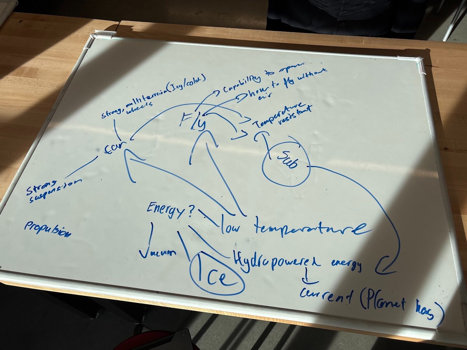
The project initiated when the team made the plan of creating a submarine prototype. A board with ideas were listed and it was later decided that a submarine would be the vehicle suitable for the planet that was chosen. Multiple precautions were also listed so these situations could be avoided. Unfortunately, buoyancy was not listed and did become a big problem factor in the first test.
Design
The first CAD design was created. The plan was to have the motor and battery completey sealed inside the submarine, the motor propels a propeller shaped module from the inside with magnets stuck to the module. Then a similar shaped module with propeller fans is on the otherside of the same wall with magnets in so the magnets would stick together in sync to propel the vehicle design. Due to a number of new changes there were not any saved photos of the first CAD design. The two photos listed below are the propeller modules.
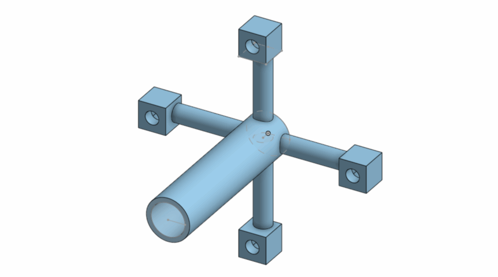
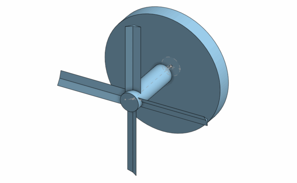
The propeller module on the outside is also designed differently because the circular shape stuck to the wall would decrease the most amount of resistance while spinning in water so the actually propeller fan would push the submarine forward.
A watertight body was also created named Body V1 (version 1 – there were not any photos for this body), it is shaped a cylindar with 2 opennings 2 lids(second photo under NEW DESIGN section) were created to cover. There was also a motor holder to keep the motor up parallel to the cylinder. The plan was to put the battery and motor connected inside after attaching the module. Next, close the lids and then put the outer propelling module on the wall(one of the lids). After the lids go in the submarine is sealed with water resistant tape to watertight the submarine.
Test V1
In the actual test, the motor was not powerful enough to battle the friction between the modules and the lid which caused it to stop spinning. Instead, a watertight test was more appropraite since it could give some information needed and demonstrate progress. The results of the test stated that the vehicle was watertight, but unfortunately the buoyancy issue was not considered and the submarine was not able to submerge under water.
From the results of the test, a conclusion was made to stick with the original propelling plan but requiring a stronger(torque) motor. A shell was also designed to hold water to battle the buoyancy in the water so the submarine could submerge and travel under water. If the buoyancy issue is still unsolved extra weights would be applied to the vehicle.
New design
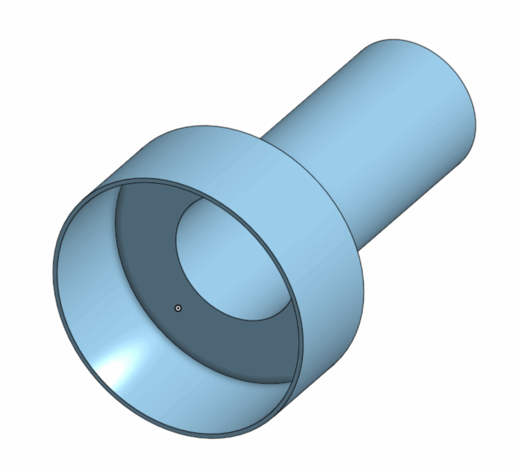
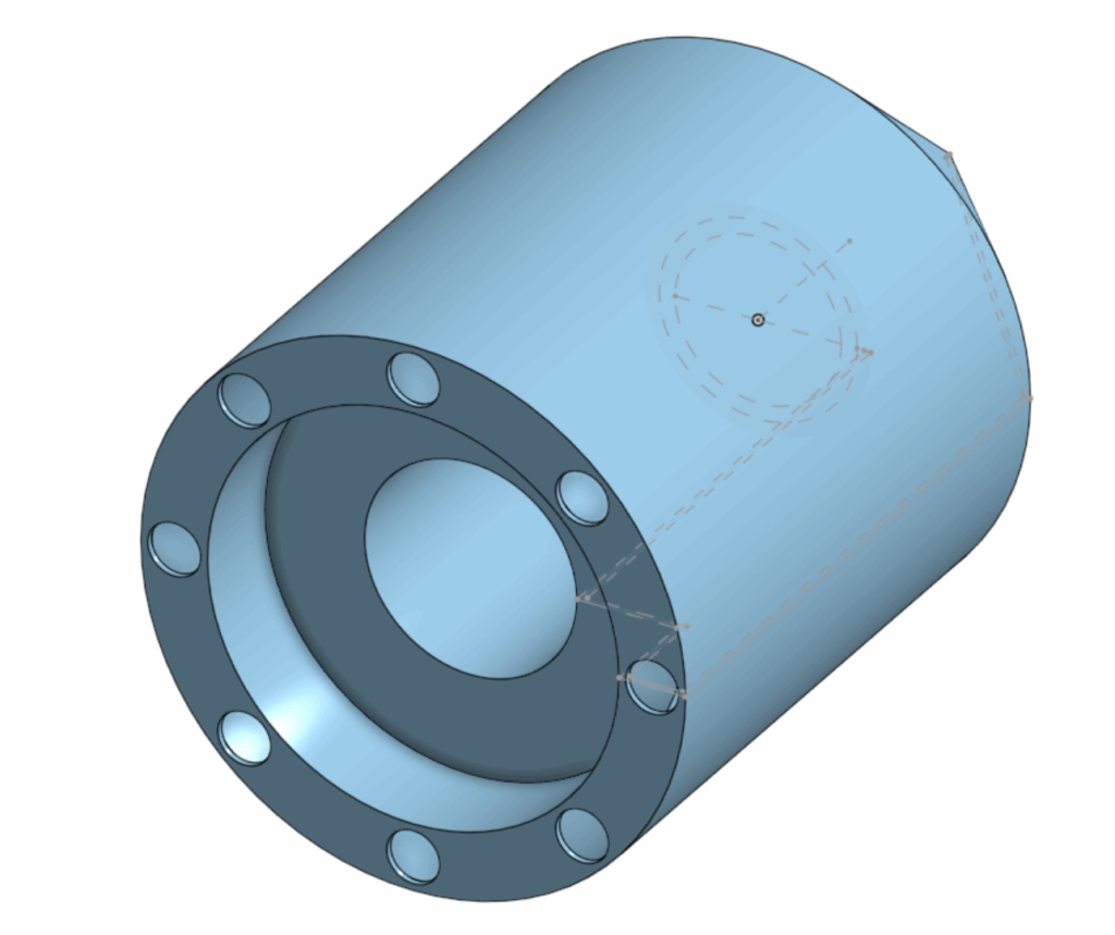
The 3 photos above are the 3 main parts of the design. The first photo is the new body of the submarine. The body was no longer a shape of a cylinder, the design achieved taking away as much area for air as possible so the shell is not required to be really large. The second photo is the lid, the thickness of the wall was also minimized for better magnetic reactions between the magnets while still being watertight. The last photo is the shell, there are 8 holes designed around the side for water to flow in to counter the buoyancy. The larger hole in the middle was for the vahicle body to fit perfectly in. Water resistant tape is also added in the inside of the body to make sure the design was as watertight as possible.
The Final Test
When the test initiated, the method of making the motor spin inside the body was to place the motor into the body while the motor was running. The procedure was to open the lid, place the battery and the motor with the motor centering module on into the body while the motor was spinning, then close the lid as it also pushed the motor to a designated distance inside the body. After the lid is closed, water resistant tape was placed around the lid so that no water was able to get into the body. When the tape was on the last step was to align the magnets of the outer propeller with the inside module. The major problem was that the motor was spinning at a high speed meaning that the magnets were not able to stick together without trying to sync the magnet from the outside as well(a good reference to this scenario is a scene in the movie “Interstellar” by Christopher Nolan where the protagonists space ship had to rotate and sync with the larger ship so they can connect and travel further/survive). Methods were tried to sync the magnets onto the wall of the lid, for example humanly spinning the module at a speed but was not fast enough to sync with the rotation of the inside module causing this method to fail. Another method was also conducted which was to let the magnets sync on the lid before the motor was placed in the body humanly, but the hole fore the motor was too deep and the module rotating at high speeds was hitting the fingers of members who were trying to place the motor in. Multiple other methods were tried until the battery inside the body died and ran out meaning that the vehicle was not able to move.
Even thought the vehicle was unable to demonstrate movement, a buoyancy test was still performed on the vehicle afterwards. The results were that before extra weights added the submarine was able to submerge deeper than the first test due the the new shell design, but around a fifth of the shell was still unsubmerged. After adding weights to the vehicle, the submarine was able to submerge underwater and maintain the position and pointing direciton the vehicle was designed to(sideways in water).
Data
Unfortunately the test “failed” because the basic requirements for the prototype was not met. The vehicle was not able to move also meaning that the energy efficiency of the vehicle is 0%. The input energy was a 9V power source of a battery.
Analysis
Even though some data was retrieved, the important data of speed and distance was missing. Assumptions of these data had to be made for the analysis. The motor was strong but would have had to battle friction in the water so it may slow down. The fans of on the propeller were not angled aggressively so the speed would not be too fast. The shell was designed to be fluid dynamic. So the speed was estimated to be around 1m per second. The distance is estimated to the distance of the testing area in the pool. The distance of the pool is 15-20m
Using these assumptions, the energy efficiency was able to be calculated. With an input voltage of 9 V. AI was used to estimate the current and gemini provided data of 0.2-0.6 amps on a light motor, the system power was calculated to be 9 W. Assuming an estimated speed of 1 m/s and an expected travel distance of 15–20 m, the total operating time would be approximately 15–20 s. This results in an estimated electrical energy input of 135–180 J. Due to energy losses from water resistance, internal friction, and inefficiencies in the motor, only a fraction of this energy would be converted into useful mechanical motion. The energy efficiency is calculated to be 38.5%, the available mechanical energy would be in the range of 20–27 J. This analysis suggests that while the theoretical energy supply may have been sufficient for short-distance movement, inefficiencies in propulsion would cause a lack of forward motion/speed.
                                                         25J
Energy Efficiency = ------------------------
                                                9V x 0.4A x 18s
                                                  25
                                        = ------------
                                                 64.8
                                        = 38.5%
Conclusion
In conclusion, the vehicle prototype was not able to move, but through estimation of data the important information was retrieved. The design could have been improved in multiple ways. The vehicle could have been designed to propel in a different method. The vehicle could have also be design way better in a way so that buoyancy would not be an issue.
AI
Leave a Reply to jacoby Cancel reply