Physical Prototype
Arduino Code
#include <Servo.h>

int red = 9;
int yellow = 8;
int green = 7;

Servo signServo;

int servoPin = 13;

void setup(){

  pinMode(red, OUTPUT);
  pinMode(yellow, OUTPUT);
  pinMode(green,  OUTPUT);

  signServo.attach(servoPin);
  signServo.write(0);

}
void loop(){
digitalWrite(red, HIGH);
 delay(3000);
digitalWrite(red,  LOW);
signServo.write(180);

  digitalWrite(yellow, HIGH);
delay(1000);
  digitalWrite(yellow,  LOW);
delay(500);

digitalWrite(green, HIGH);
delay(2000);
digitalWrite(green,  LOW);
signServo.write(0);

digitalWrite(yellow, HIGH);
delay(1000);
  digitalWrite(yellow,  LOW);
delay(500);

}
For my robotics assignment, I decided to create a simple traffic light mechanism. I chose to keep this project simple due to my limited prior experience in robotics, and specifically Arduino. To provide an overview, this mechanism utilizes three LED lights to represent the red, yellow, and green lights in a traffic light. The LEDs are controlled by a timer, which triggers the swap of the active LED at the appropriate time. A mechanism rotates to change the sign from “Go” to “Stop” whenever the active LED changes.
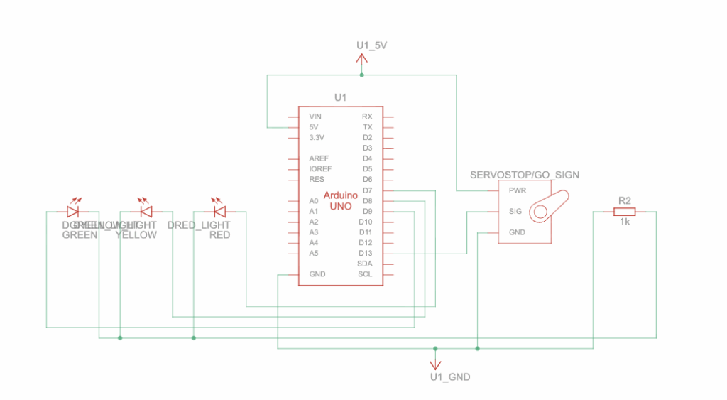
This circuit schematic demonstrates how the Arduino circuit actually functions. To start, the Arduino UNO acts as the brain of the circuit, and controls which LED is turned on at which time and when the servo motor moves. Specifically, the Arduino UNO is the power source of the circuit, providing power to the lights and motor and storing the uploaded code. Next, the LEDs are split into 3 colours: green, yellow, and red. Each of these LEDs have two pins that conduct power from pins D7, D8, and D9 on the Arduino. The LEDs are connected to a resistor, marked by R2 on the right, with a resistance of 1k Ohms to limit the current flowing from the Arduino pins and prevent overloading the circuit.
Following this, the Servo Motor (Stop & Go Sign) has three ports, each with a unique purpose, that receive power from the Arduino to rotate a small motor, which swaps the signs. As indicated by the wires, the power port connects to the 5 Volts output on the Arduino, which gives the servo the electricity needed to function. The GND port connects to the Ground, which completes the circuit so the current can flow properly. Lastly, the SIG port connects to the signal, which allows the Arduino to send instructions from the code to the servo, allowing it to rotate at the appropriate time.
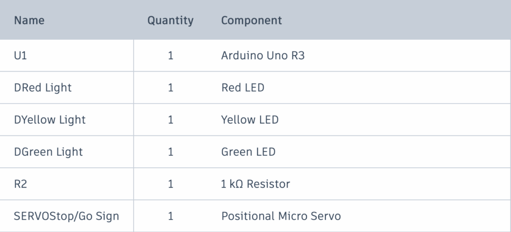
Attached above is the Bill of Materials for my traffic light project. The Arduino UNO R3 is the model of the actual Arduino circuit board. The LEDs, combined with the resistor, act as the traffic lights. The Positional Micro Servo indicates a motor that rotates based on given positions, rather than in continuous motion. Aside from this, female-male and male-male wires, as well as a breadboard, are needed to create the design.
#include <Servo.h>
// import the servo motor library

int red = 9;
int yellow = 8;
int green = 7;
// define which pins on the Arduino each LED is connected to.
// set the variable values to "Integers" to accommodate the Arduino pins.

// lines 1-8
The code for this project is relatively simple due to the repeated use of similar commands. To start, the #include <Servo.h> imports a special library into the code that allows the Arduino to control the servo motors with many pre-set functions with parameters. Next, 3 variables are defined for the 3 LED traffic lights. The values of the variables determine which pins on the Arduino the LEDs are connected to.”int” restricts the variables’ defined values to integers to accommodate the integer numbers on the pins on the Arduino board.
Servo signServo;
// Connects the servo motor to the Arduino board and allow the Arduino to send commands to the motor.

int servoPin = 13;
// Define the Arduino pin the servo motor is connected to.

// Lines 10-14
Following this, a servo object is created using the imported “Servo.h” library. “Servo” prepares a servo object to be used from this library, while the “signServo” function gives this object a name. Because the servo motor is physically connected to the Arduino board, this function acts like a remote control that allows the Arduino to send commands to the servo. Similar to the LEDs, the “int servoPin” defines which Arduino pin the servo will draw power from.
void setup(){
// Prepare the LEDs and servo motor for use.

  pinMode(red, OUTPUT);
  pinMode(yellow, OUTPUT);
  pinMode(green,  OUTPUT);
// Tells the Arduino that the LEDs will output power

  signServo.attach(servoPin);
// Connects the previously defined servo to the defined pin (13).
  signServo.write(0);
// Set the servo to its original position.

}

// Lines 16-29
Moving on to the setup function, the main purpose of this portion of the code is to prepare the LEDs and the servo for use, which will be defined in the next few lines. Firstly, the “void” command tells the Arduino code that the following function will not return a result, as it will instead direct power to the LED pins. The “pinMode(colour, OUTPUT)” tells the Arduino that the LED pins are sending power out. The “signServo.attach(servoPin);” connects the previously prepared servo to the “servoPin”, which was defined as pin 13 on the physical Arduino. Finally, the “signServo.write” function sets the position of the servo motor to 0 degrees (starting position).
void loop(){
// Creates a forever loop
digitalWrite(red, HIGH);
// Determines whether when an LED needs to be active, and setting its power to high to turn it on.
 delay(5000);
// Causes the above LED to stay on for 5 seconds before changing.
digitalWrite(red, LOW);
// Turns the active LED off.
signServo.write(180);
// Turns the servo 180 degrees, flipping it from its starting position to display a new sign.

}

// Lines 31-40
To end, the loop function, without any parameters, keeps the rotation between the green, yellow, and red lights running forever. The “digitalWrite” function sets the power of the LEDs. In the showcased example, the red LED starts at a high power, turning it on. The “delay” function, counted in milliseconds, ensures that this function runs for 5 seconds before switching the red LED’s power to low, turning it off. Following this, the servo’s position is updated to 180 degrees, effectively flipping it from its starting position to display a new sign. This code is repeated for each of the 3 LEDs, and restarts at the end due to the forever loop.
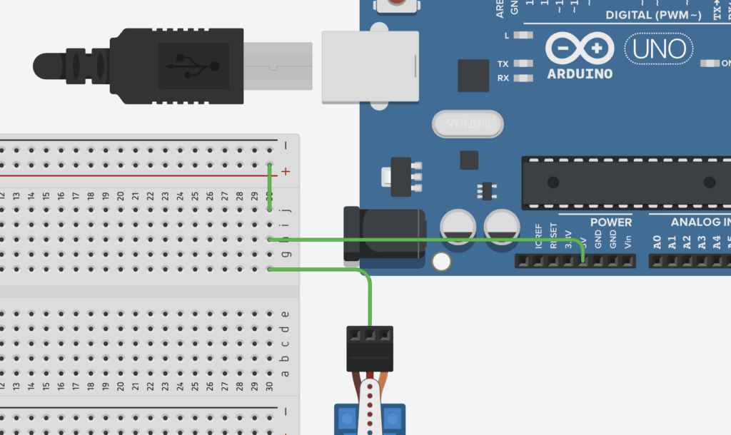
Showcasing the physical model, a key difference in circuitry I noticed between it and the virtual prototype was that multiple wires could be connected to a single port on the virtual version. For instance, the power for the LEDs and the Servo Motors could be directly attached to the 5V output on the Arduino Board, whereas on the physical model, I had to find a workaround by connecting the 5V pin to a single line on the breadboard, before attaching the LED and servo wires to that line.
Despite this, I found that the process of making my physical prototype was an overall success, as it was easier than expected to connect each wire to the correct port, to upload the code to the Arduino, to find the correct parts, etc. In the end, I decided against attaching a Stop/Go sign to my servo motor so as to not damage the motor, but I am content understanding that the design functions properly.
AI Transcript
Below is a transcript of my AI usage. Because of my limited prior experience using Arduino in robotics, my main purpose for the use of AI was to learn the foundations of Arduino components and their specific coding language. I found that ChatGPT was the most suitable tool for this as it is able to explain complicated functions in simple terms, as well as with the help of useful analogies.
Leave a Reply