Introduction
This planetary explorations project provided my team members and myself with the unique opportunity to explore an exoplanet of our choosing and design a prototype for a hypothetical vehicle that could traverse it. Throughout the design process of this vehicle, we considered factors such as terrain, energy efficiency, and structural integrity, to create an effective and innovative solution. Ultimately, heading into the testing phase of this project, we sought to build a vehicle prototype that overcame these challenges, taught us valuable lessons (about engineering and design), and revealed the implications of these test results on our exoplanet, Teegarden’s Star b.
During the early stages of the project, we developed a specific, and clear definition statement to guide us through the process. It details all of the challenges that the vehicle needed to overcome, the exoplanet’s conditions, and the implications of these elements for our proposed solution. Here is the full definition statement:
Four human astronauts need a safe and efficient way to travel 10 continuous km across Teegarden’s Star b due to unique atmospheric, gravitational, and geological conditions. We must overcome challenges such as a differing gravitational pull, rocky terrain, and uncertain atmosphere by creating a testing environment that models these conditions.
Our solution to overcome the several challenges stated in the introduction experienced several changes/alterations from the beginning to the end of this exploration.
Early Stages
In the early stages of ideation, we honed in on specific functions of the vehicle, brainstorming solutions for each function. We later put together our findings for each function to create a vehicle that could traverse the terrain of Teegarden’s Star b.
Mobility:
Based on our background research for our planet’s surface, we believed that our system for mobility must include traction, stability, power, and endurance. We considered three primary features: A solid wheel based system, treads, and spider legs (for climbing rocky terrain).
Here is an image of our physical brainstorming whiteboard:
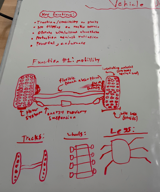
- Wheel based system
For a wheel based system, we conducted research on several off-roading and heavy duty vehicles, allowing us to take inspiration and apply it to our vehicle. Firstly, we made the observation that many vehicles built to traverse mountainous terrain, such as the Jeep Wrangler use a wide tire base, along with a mud terrain tire pattern. We learned that a wide tire base could be essential in providing stability, weight distribution, and traction surface. It does this by distributing the vehicle’s weight over a larger surface area, resulting in a lower ground pressure. Secondly, we learned that suspension would be essential in maximizing traction, absorbing high-impact shocks from rough terrain, and providing stability. During our initial research, we observed that many of these off-roading vehicles use a coiled spring suspension, which is what we later used in our vehicle design. Finally, we found that the axle must be firm yet flexible, allowing the parts of the vehicle to move in unison, and increasing its ability to climb rocky slopes.
- Treads
Throughout our research, we found that several secure vehicles such as tanks utilize treads to reduce ground pressure, increase off-road mobility, and provide better grip for climbing steep hills compared to wheels. This was intriguing to us, during our initial research, however we also considered the negative effects of treads. These included a significantly limited maximum vehicle speed, a poor energy efficiency, and a reduced control system.
- Spider legs
For a large part of the early stages of our project, we considered spider legs due to their unique ability to effectively climb mountainous terrain, provide stability, and reduce dependence on atmospheric conditions. Unfortunately, our research showed that spider legs also included risky features such as a high centre of gravity, maintenance requirements, and weight vulnerability. Choosing not to proceed with this mobility system was a significant change throughout our process.
Body design:
Based on our background research, we believed that the body of our vehicle must focus on three primary elements: shape, thermal insulation, and the optimal materials. Although all of these elements are crucial in testing our vehicle on Teegarden’s Star b itself, this project narrowed our focus down to the vehicle’s shape. This was due to the fact that radiation and solar flares were extremely difficult to test and may have provided misinformation about our vehicle’s performance.
Here is an image of our physical brainstorming whiteboard:
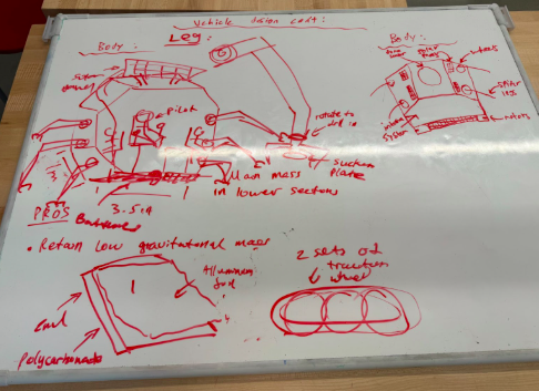
- Shape
Regardless of the mobility system we chose, we concluded that our vehicle’s shape must include hexagonal designs. Hexagons have been proven to provide the most structural stability, optimal weight distribution, and largest surface area. Structural stability and weight distribution are essential in traversing the rocky terrain of Teegarden’s Star b; Specifically, when climbing steep slopes, hexagons share the pressure from external force and weight, preventing the bending or collapsing of walls. For these reasons, we believed that a hexagon would be optimal for our test, however we also considered other angular configurations such as trapezoids and rectangles. For similar reasons, we concluded that while hexagons are optimal, these angular shapes would also be suitable.
- Thermal insulation + Material
While we could not directly test thermal insulation during this project, it remained a significant factor to consider, given Teegarden’s solar flares and potential radiation. Conducting extensive research led us to the conclusion that we would use polycarbonate in the form of rigid hexagonal panels, as an outer shell. Polycarbonate blocks almost the entire UV spectrum, including UVA and UVB rays, which would significantly protect our vehicle throughout its journey. Moreover, through utilizing this material in the form of micro hexagonal panels, and their rigid fit, we learned that our vehicle could safely reflect or absorb radiation.
Energy, Fuel, & Power
Modeling our solutions for energy, fuel and power were difficult, which is why we ultimately used an Arduino circuit. However, during our early brainstorming sessions we established three primary features of this system: solar panels, a motherboard (to control all vehicle systems), and a lithium ion battery pack.
Here is an image of our physical brainstorming whiteboard:
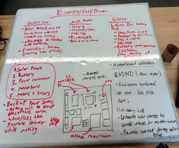
- Solar panels
Due to the extensive exposure to solar radiation and flares, we sought to leverage our environment to our advantage through harnessing its energy. Through the installation of solar panels, our vehicle would intake energy without dependence on an atmosphere, which was a significant reason for this choice. Moreover, making these solar panels adjustable to intake solar radiation from various angles and quantities, would equip our vehicle with the longevity to successfully travel the required distance.
- Motherboard
Our initial motivation behind a motherboard was a simple way to control all systems of the vehicle, from one compartmentalized place. However, after conducting research, we also found that the Mars rover RAD750 uses a motherboard similar to what we envisioned. Therefore, we were able to draw inspiration from this, including components such as a bridge chip, a voltage revolver, an L2 cash, and others. For more information on the motherboard, here is a visual of what it would have looked like.
- Lithium Ion Battery Pack
Finally, for another source of energy, in the event of a hardware issue in the solar panels, we chose a lithium ion battery. We found that these could be rechargeable, provide short and strong bursts in crucial situations, and easily integrated into the vehicle system. For these reasons, we chose this for our backup option, however we simulated this through the use of a traditional AAV battery pack.
Design Path Selection & Justification
Selecting an effective and efficient path for each of the elements previously discussed was crucial in shaping the process of our vehicle design. These fundamental aspects of the vehicle included its shape, mobility method, and additional features.
- Shape
While we did consider a hexagonal shape at first, the shape’s geometry presented challenges when mounting motors and aligning axles, as the angled edges reduced the available flat surfaces required to attach additional components. This led us to pivot towards a rectangular shape for our first test and for the rest of this project, as it provided long, parallel edges that simplified motor installation, improved axle alignment, and increased structural support for the materials at hand. Moreover, we reasoned that for our first test, the priority would be testing the robotics components to ensure that the vehicle moved efficiently and carried enough energy to traverse our terrain.
- Mobility Method
In terms of our choice between treads, spider legs, and wheels, we ultimately decided to proceed with a wheel based system. We deemed that the risks of the spider legs supporting the vehicle’s weight and effectively moving in direction eliminated this option for our prototype. In addition, we found that using treads would expose the vehicle to rapid changes in direction, and the slope of mountainous terrain. Therefore, we selected a wheel based system, because reviewing our background research reminded us that the sheer size and detailed patterns of the tires would be best for our planet’s terrain.
- Additional Features
In terms of adding additional features to support and guide the vehicle strategically through the test environment, we sought out to create a ramp and a suspension system. However, the need for these systems were evident after our first test, as prior to this test, we believed in a simplistic design which included simply the essential features. More on these features after the debrief of our first test and iteration.
1st Physical Iteration
CAD Design:
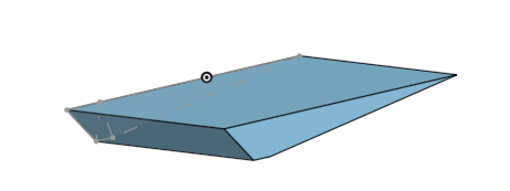
In the development of our 1st iteration of our vehicle, we used CAD minimally, as we did not find a need for 3D printing or complex features. However, we did use it to visualize the base of our vehicle.
Here is an image of our base in Onshape:
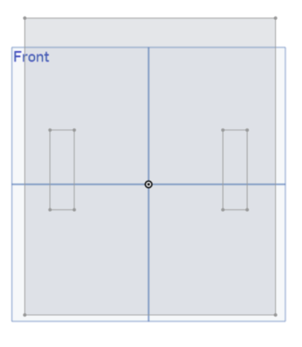
As mentioned previously, this rectangular base would serve as a suitable base for our first test, as we learned to acquaint ourselves with the movement of our vehicle.
Physical prototype:
- Base
For the rectangular base of this first prototype, we used a sheet of foam board about 16 x 18 cm. We believed that foam board would be a sturdy, yet lightweight material for our first test, and that these dimensions would be an optimal balance to secure our centre of gravity.
- Wheels
In terms of the specific wheels that we chose, we reasoned that standard Arduino wheels would be optimal for our base due to their appropriate size and deeply engraved tire patterns.
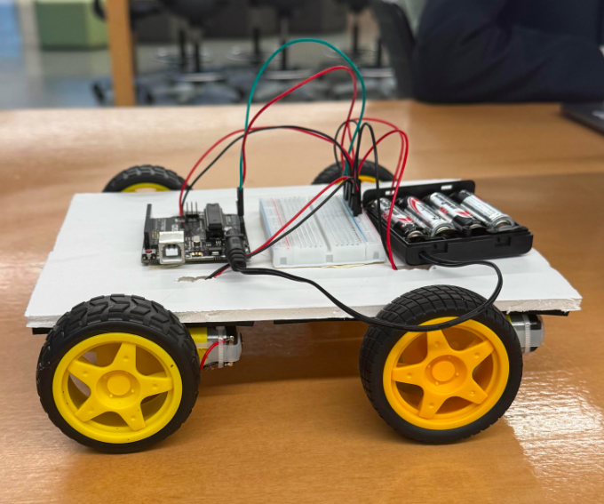
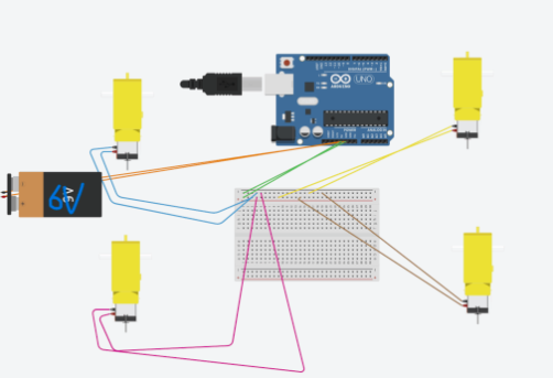
- Electronics
For the electronics portion of our first prototype, we used a simple Arduino Uno and a breadboard to distribute power to all motors. Our circuit also included 4 AA batteries placed in a battery holder and connected to the Arduino Uno, effectively powering the vehicle. Finally, we wired the motors to the power source, by connecting 2 male-male wires from the 5V and the GND of the Arduino to the VCC power rail and the GND power rail.
Here is an online image of our circuit:
Test Day #1
The purpose of our first physical prototype was to test how effective its mobility system would be against both flat surfaces and mountainous terrain. At this stage, we prioritized whether or not it could overcome such terrain with the current wheel based system, rather than testing specific features that would assist it in this. Energy efficiency testing would come during our second phase.
Specifically, we decided to test the vehicle’s ability to traverse and combat various conditions and terrain.
- Flat/smooth surface
Before testing any unique sorts of terrain, we decided to establish the traditional plywood base as a constant used to measure relative performance. We tested the vehicle’s performance travelling 2 metres in a straight line, and this proved to be an overall success. However, the back left wheel was positioned too high on the side of the base, therefore it was unable to turn effectively, causing a reduced efficiency in the vehicle. This significantly impacted its ability to travel in a straight line, hindering its sense of direction. Finally, we had to hold the battery pack and walk as the vehicle moved, which was problematic, as we had no way of turning the vehicle on and off from a distance.
- Paper balls
A similar yet even more challenging test can be discussed for our vehicle when analyzing its performance against paper balls. While we faced similar challenges to our first test in terms of the various elements such as electronics, this obstacle brought to the surface a new fundamental problem. This problem was the fact that our vehicle had no suspension system or way to climb uneven terrain or overcome obstacles. To combat this, we learned that we would need to implement a strategic suspension system that would allow the vehicle to climb mountainous terrain.
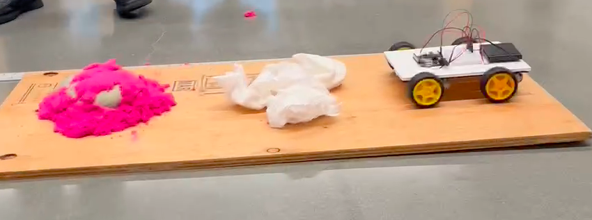
- Rocky Terrain + Sand
For this aspect of our project, our vehicle could not climb over the rocks or the slope of the sand. This was our final reminder that we absolutely needed to prioritize a suspension system. Finally, to facilitate this test, we used foam rocks and kinetic sand.
Here are some videos of our first test:
2nd Physical Iteration
For the second iteration of our vehicle design, we decided to hone in on a way to climb slopes and mountainous terrain. At the same time, we also had to ensure energy efficiency.
Design alterations:
- Spring suspension system
As previously mentioned, it was evident that we needed a way to climb mountainous terrain, because our previous design was too low profile and delicate. Through utilizing a spring suspension system, we aimed to tackle these problems, and maximize energy efficiency during climbing phases.
- Underside ramp
In addition to a suspension system, we also needed a feature that would allow the vehicle to have a large amount of momentum during its uphill ascent of a slope. This where a ramp on the underside was implemented.
- Wooden base
After witnessing how the first prototype’s delicacy hindered its ability to overcome various obstacles and terrain, we decided to create a new, wooden base. This base was installed to stabilize the vehicle and allow it to climb with more security.
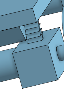
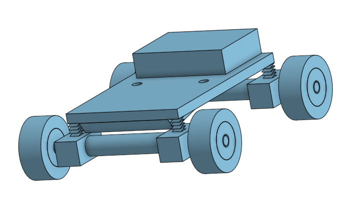
Final CAD Design:
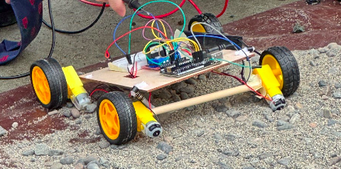
Test Day #2
For our second test day, our vehicle unfortunately did not function at all; it simply did not move across our intended terrain. For context, our testing environment for this test was in large part similar to our first test, however the only change was that instead of foam rocks, we used gravel. This was a direct result of our electronics components and structural designs.
Firstly, the copper wires that we used were thin and flexible, making them unable to reach the holes on the breadboard. As a result, the wires did not receive current from the breadboard, causing the test to fail.
Secondly, the spring suspension was not securely attached to the base and motors. This was extremely problematic due to the fact that the vehicle became fragile and easily prone to structural damage.
Thirdly, the wheels of the vehicle were far too wide, and the corresponding wooden dowels used as the axes were also too long. Although this happened to be a mistake in our measurements, it was still a major flaw in our design due to the fact that it made the vehicle fragile.
Energy Efficiency
Subsequently, a failure in our vehicles movement ability led us to an energy efficiency of 0%. Due to the fact that the voltage being supplied was not turned into useful energy, it led us to realize that we would not be able to measure other values and calculate efficiency. However, to gain a better understanding of how our vehicle would fare with a functioning electronic system, we used the measured values of another group’s vehicle to perform calculations.
Here is an image of the calculations performed by hand:
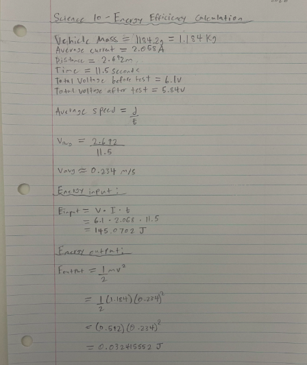
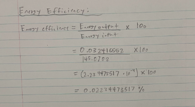
The final efficiency we found for this comparative test was about 0.02234 %, which is an accurate representation of what our energy efficiency would have been, based on our structural flaws.
While it was simple to calculate this energy efficiency, we did formulate an original plan to measure it for our own vehicle. This plan included, using the formula for energy efficiency through values such as input and output energy. Our input energy would have been found using the formula in which the average voltage, average current, and time are multiplied.
Meanwhile, our output energy would have been found using the formula for kinetic energy, as it represents the useful energy that was used by the vehicle. Other than this comparative calculation, there was nothing else that we could have measured when calculating energy efficiency. The same can be said for creating graphs and other visual representations of data.
Conclusion
After undergoing the design process, I have drawn the conclusion that for a project such as this past vehicle project, it is wisest to begin and solely focus on the vehicle’s mobility and structure. In the beginning of this project, we spent some time considering fuel and power, however those considerations did not prove to be useful for our tests, due to our usage of standard electronics.
Moreover, this project reminded me of the importance of self advocacy and establishing firm boundaries within team projects. Our group did not successfully work together to achieve one goal, and had it shown cooperation from all members, our final result would have been different. Finally, the largest takeaway from this project for me was the importance of a flexible, yet rigid wheel base.
After watching other groups’ tests, I learned that many of them used wheel bases that could adjust according to the vehicle’s movements. For example, the Trappist 1 group’s usage of a “rocker bogey” system taught me the importance of flexibility, as it allowed their vehicle to persist amid all conditions.
The implications for this vehicle on the surface of Teegarden’s star b would not lead to success. This is due to the vehicle’s lack of a secure suspension system, and flexibility in the wheel base, causing it to struggle significantly when climbing mountainous terrain.
Ultimately, I learned about several unique elements of design, the application of physics, and other skills such as team cohesiveness throughout this project. It was a truly unique experience that I will forever learn from.
AI Usage
Artificial Intelligence was used to guide me through my relatively novice CAD skills in Onshape.
Here is a transcript of my usage:
Leave a Reply to mcrompton Cancel reply