November 1st, 2025
This project was intended to demonstrate an ability to showcase basic robotics skills through the usage of Arduinos (both virtually in TinkerCad and physically built). As someone who had never even heard of Arduinos or robotic terms before, this project was certainly a challenge for me. Over the course of this project, I had to learn basic TinkerCad skills, circuit building with Arduinos, what Arduinos were and how I was going to use them, Arduino programming language, and much more. I relied on AI, specifically Chat GPT heavily throughout the project, to guide me, teach me, and educate me on several different topics. A reflection on my usage of it will be present at the very end of this post.
As for the project itself, I decided to create a basic (not so basic for me as a beginner) gate which would open and close. I built this through the use of a servo motor which was programmed by my code and connected to the Arduino. In this blog post I will cover each part of the project, however keep in mind that I did not create the physical model due to technical difficulties and alterations to the original assignment.
Virtual Prototype
Step 1: Bill of Materials (BOM)
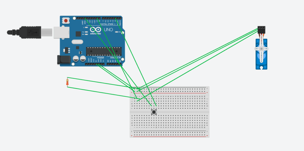
Of course, before beginning the construction of the virtual prototype, I had to determine exactly which various parts would be needed. Firstly, an Arduino Uno R3 would be needed to facilitate the project. Secondly, a breadboard was needed because while I first wondered why we could not just connect wires from component to component directly, I learned that a breadboard would avoid the need to solder wires physically. Thirdly, a micro servo was needed to rotate the gate. Fourthly, a push button was needed for the user to engage with the circuit. Fifthly, a resistor was needed to prevent the over supplement of energy to the button. Finally, jumper wires were needed to connect all of the components to the breadboard.
| Component name: | Quantity: | Notes: |
| Arduino Uno R3 | 1 | Microcontroller controlling servo |
| Breadboard | 1 | For connecting components without soldering |
| Micro Servo | 1 | Connected to pin 9 |
| Push Button | 1 | Connected to pin 2 |
| Resistor (220 Ω) | 1 | Pull-down for button |
| Jumper Wires | 10 | Connects components on breadboard |
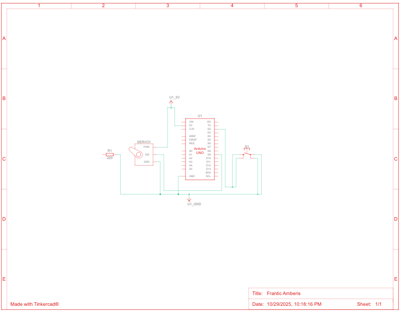
Step 2: Circuit Building (Schematic View)
As for the circuit itself, it uses components such as specific wired connections through the breadboard to function efficiently. Firstly, the servo’s ground wire (brown) is connected to the breadboard’s – rail, which is also connected to the GND pin on the Arduino board. This allows ground to be delivered from the Arduino to the servo and vice versa. The servo’s red wire connects to the + rail which is also connected to the Arduino’s 5v pin. This allows voltage to be supplied from the Arduino to the servo. The servo’s signal wire (yellow) is connected to row 2, which is connected to pin 9 through the breadboard. This allows the servo to perform functions through the Arduino’s pin 9.
The arduino’s pin 2 is connected to row 10 on the breadboard which is the same row that the push buttons terminals 2b and 1a are connected to. This again, allows the Arduino to read on and off signals based on the button’s press. The ground pin on the Arduino connects to row 8 on the breadboard to allow other components such as the resistor and the button’s other two legs to read “low” (when the button is not pressed), so that the circuit can return to ground.
Finally, the resistor is connected to the ground rail on the breadboard and row 3 to prevent an overload of power flowing through the circuit.
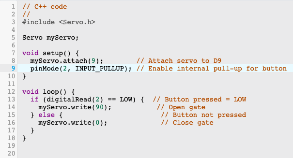
Step 3: Coding
For the coding portion of this project, I asked Chat GPT to first write it out, then explain it to me, and then guide me through writing it out myself. This portion may have been the most challenging for me, as I had to learn a whole new language. However, throughout the process of learning this language, I related it back to my understanding of Python commands, which helped me understand similar concepts in different words.
Line 3 tells the Arduino to load the servo library, so that it can understand future commands such as “myServo.attatch(9);”.
Line 5 is like defining a variable in python. It gives a name to the servo motor, so that Arduino knows that there will be a servo involved and what it is called.
Line 7 starts the setup function which occurs when the Arduino is turned on or resets. The curly bracket stores the setup commands to come.
Line 8 attaches the servo to pin 9, telling it which pin to send control signals to.
Line 9 tells Arduino to treat pin 2 as an input pin. This means that through this pin, it will read whether the button is pressed or not, setting up later commands.
Lines 12 through 18 contain a loop that repeats forever containing crucial if else statements that form the base of the code. It says that if the button is pressed (reads LOW), the servo will rotate 90 degrees, and if not, it will return to the same position (0 degrees).
Step 4: Functioning Prototype Video
Here is a video of the functioning prototype!
Step 5: Physical Building Attempt and Learning
I was not able to document my attempt at a physical prototype, however I did learn some things during the process. One thing I learned was that, while you may connect more than 1 wire to a pin in TinkerCad virtually, you cannot do the same physically. This is why I ended up adjusting my virtual model to look more like a physical one. I also got a general feel for physical circuit building, connecting wires, buttons, and other components. While I did not end up creating a functional physical prototype, I did give it an attempt, and learn some things along the way which I would not have through my virtual prototype alone.
Throughout this project I relied heavily on AI to teach me how to build my virtual prototype, write my code, come up with my BOM, and educate myself on how Arduinos and circuits work. As a beginner, I feel that I used it to enhance my learning, and I felt that I needed to rely on it as much as I did to eventually understand the concepts that were once completely foreign to me. Here is a transcript of my AI usage:
Robotics Project AI Transcript
To conclude this entry, this was my robotics project, and stay updated on my blog for more posts!
Leave a Reply to mcrompton Cancel reply