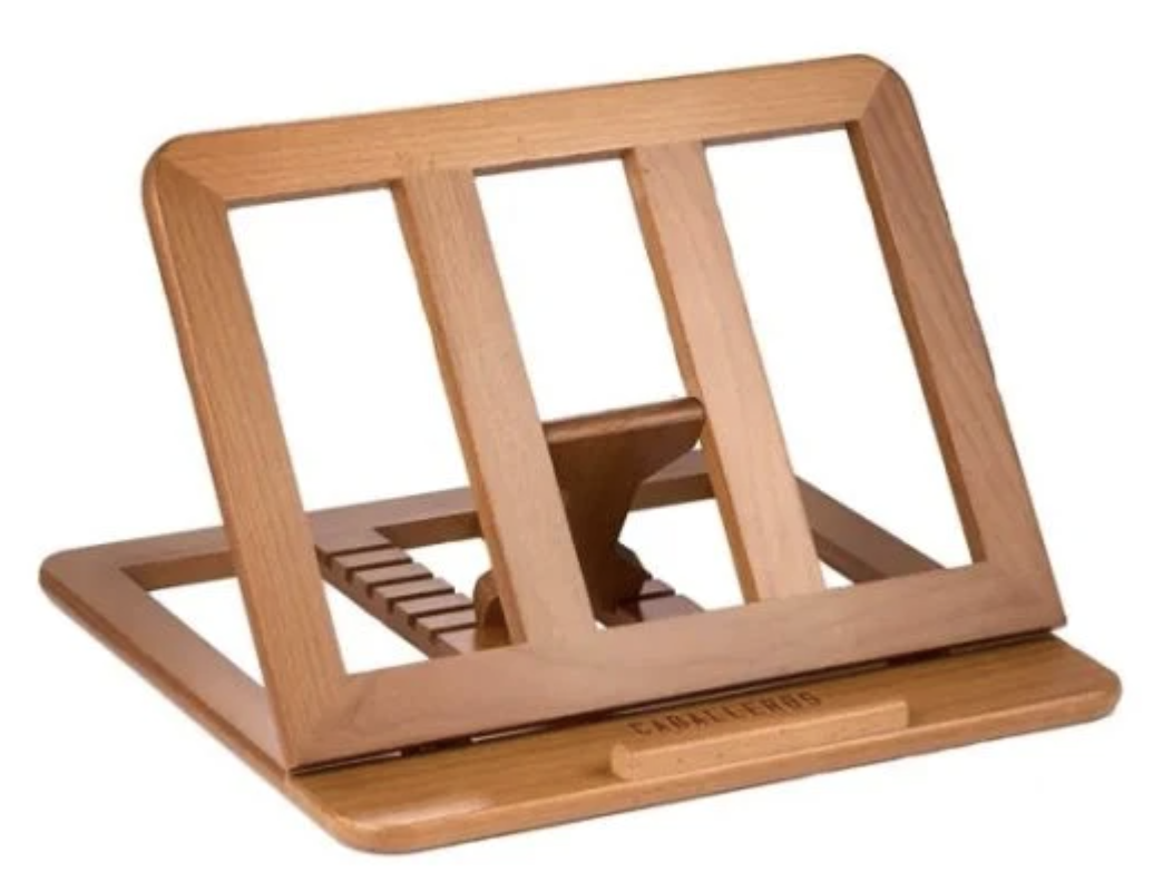
Portable Foldable Wooden Laptop Stand: SKRIVA
Problem
Most laptop stands that are made to carry around feel cheap, wobbly, and like they’re going to break after a week. I want a stand so my screen is at a better height and my laptop doesn’t get too hot, but a lot of people (including me) just leave them at home because they’re ugly or hard to bring places. That means we end up using laptops flat on tables in cafés, libraries, or class, which hurts our neck and wrists and makes the laptop run hotter, especially gaming or powerful ones.
Who I’m solving it for
Students like me who need to carry a stand to school, cafés, libraries, or when I’m traveling. Also anyone with a gaming or powerful laptop who wants better airflow and a good viewing angle at home or on the go, but doesn’t want something huge and clunky.
Definition Statement A lot of laptop stands are either too big to carry every day or they get wobbly, ugly, and don’t let air flow well when they’re made small. I want to build a slim, foldable wooden stand that’s light, looks nice, has adjustable heights for good posture, keeps the laptop cool, and doesn’t shake around, so people can actually bring it with them and use it wherever.
Research
I looked up a few things to make sure this is a real problem and to see what stands are missing.
Portability issues
Lots of stands are hard to carry or feel junky when they’re foldable.
Evidence: Remtek Workplace Buying Guide
https://remtekworkplace.com/knowledge-hub/laptop-stand-buying-guide/
They say portable stands are good for travel and working away from home, but a lot of them aren’t stable or strong enough because they’re trying to be light. People end up not taking them because they’re annoying or feel weak.
That’s why I’m making mine fold in half on both pieces so it gets really slim (3–4 cm thick) and still stays solid.
Durability and wear
Foldable stands break or get loose pretty fast, hinges get wiggly, parts bend, cheap stuff scratches or falls apart.
Evidence: Ace Office Systems blog on pros and cons of laptop stands
https://aceofficesystems.com/blogs/news/pros-and-cons-of-laptop-stand
They say portable stands have problems with durability, especially the moving parts like hinges that loosen up or wear out, so they don’t last long.
That’s why I’m using 12 mm birch plywood and a strong block in the middle with square notches wood lasts longer than plastic and won’t wear out as fast from opening and closing it.
Ventilation and overheating
Laptops get hot sitting flat or on bad stands, which makes them slow down and the fans loud.
Evidence: Ace Office Systems (same link)
https://aceofficesystems.com/blogs/news/pros-and-cons-of-laptop-stand
They say one good thing about stands is better airflow underneath, which helps cool the laptop and stops overheating. Solid or closed designs block the vents and make it worse.
That’s why I’m putting rectangular slots around the edges of the top panel so air can get under the laptop easily.
Ergonomics and posture problems
Using a laptop flat makes you hunch over, which hurts your neck and wrists after a while.
Evidence: Wired article on ergonomic experts
https://www.wired.com/story/ergonomic-experts-convinced-me-ive-been-using-laptops-all-wrong/
They say laptops make bad posture because the screen is too low and the keyboard is too high compared to your arms. A stand lifts the screen to eye level and fixes the angle, but lots of portable ones don’t adjust right or hurt your wrists.
That’s why I’m doing 4-5 different slots so I can change the angle (steep for watching stuff, flat for typing) and a lip so the laptop doesn’t slide.
Solution
I’m building a foldable wooden laptop stand out of 12 mm birch plywood. It folds small (aiming for 3–4 cm thick when closed), looks nice with real wood, and has adjustable angles with good airflow.
What I’m building (main parts):
- Base: 32 cm wide × 24 cm deep, folds in half down the middle at 12 cm.
- Top panel: 32 cm wide × 20 cm deep, folds in half at 10 cm, with a 2.5 cm high × 24 cm wide lip in the front (centered) so the laptop doesn’t slide off.
- Tilting: 4-5 slots on the base (at 6.5 cm, 7.5 cm, 9 cm, 15.5 cm, 17 cm from front), each 4 cm wide and centered. A small block (3.3 cm wide × 7 cm deep × 10 mm thick) attaches to the bottom of the top panel (centered, 3 cm from back edge) with a metal rod that lets it pivot.
- Ventilation: Cut-out slots around the edges of the top panel so air can flow under the laptop.
- When folded: The two halves stack together and connect with magnets or a latch so it stays as one piece.
How I’ll test it
I’ll check if it actually works for the definition statement with these tests:
- Portability: Fold it up completely → measure thickness (want 4 cm or less) and weight (want around 600–800 g). See if it fits in my backpack pocket easily.
- Stability: Put my laptop or 2–4 kg weight on it at every angle → type hard and push side to side → make sure it doesn’t wobble or slide.
- Adjustable tilt: Measure how high the back lifts at each slot → want 10–25° range (screen at eye level, wrists comfortable). Try typing and watching videos for 15–20 min to see if it feels good.
- Ventilation: Run a heavy app or game flat on the desk → check temps (using a program like HWMonitor). Do it again on the stand → see if it’s 5–10°C cooler.
- Looks and feel: Does it look nice on a table? I’ll ask a couple friends: “Would you carry this?” “Does it feel strong and good quality?”
Progress So Far
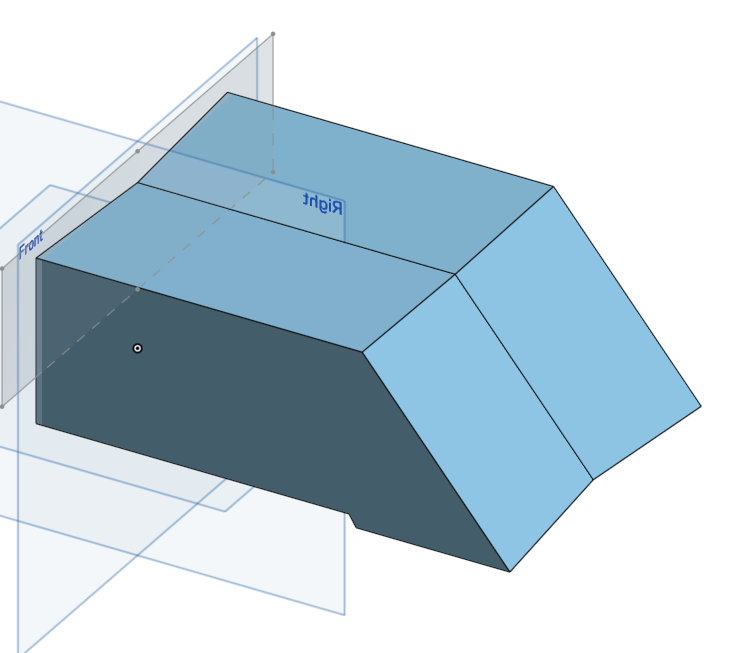
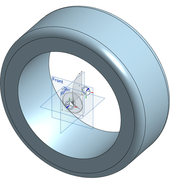
I started with paper sketches, now I have a basic 3D model in Onshape. It’s not finished — just the main idea — but it shows how the parts fit together in real life.
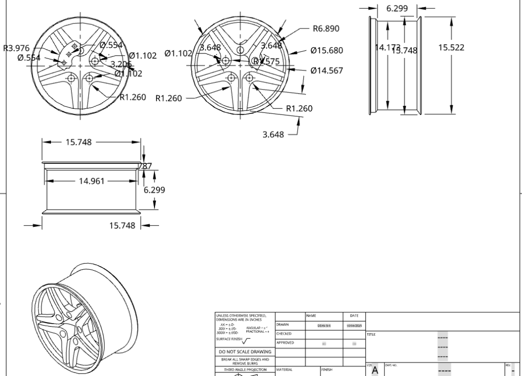
What’s in the model right now:
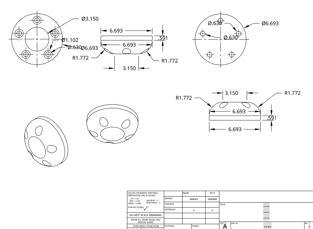
Base panel (32×24×12 mm) with hinge line at 12 cm and 4-5 centered slots (4 cm wide, 5 mm deep) at my depths.
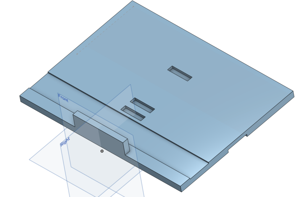
Top panel (32×20×12 mm) with hinge line at 10 cm and front lip (2.5 cm high × 24 cm wide, centered).
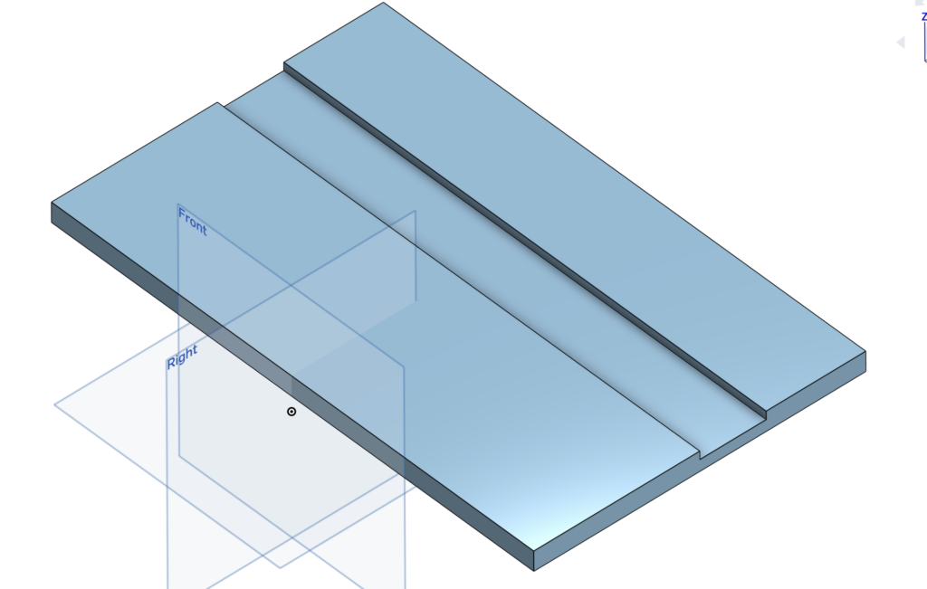
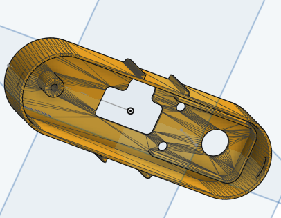
I made a recessed area at the back edge of the base for the tilting hinges (1.5–2 mm deep so they sit flat and don’t add extra thickness when closed).
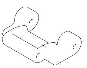
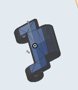
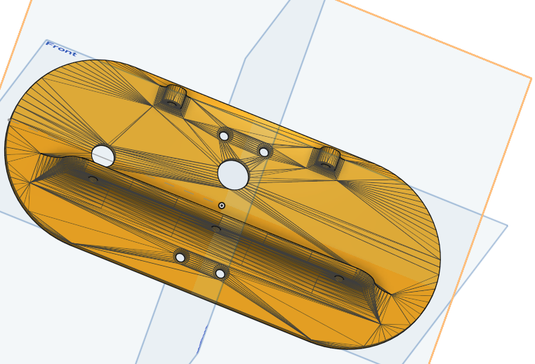
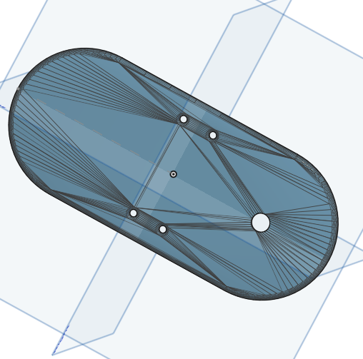
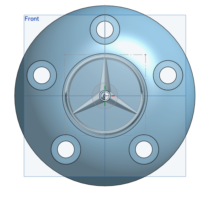
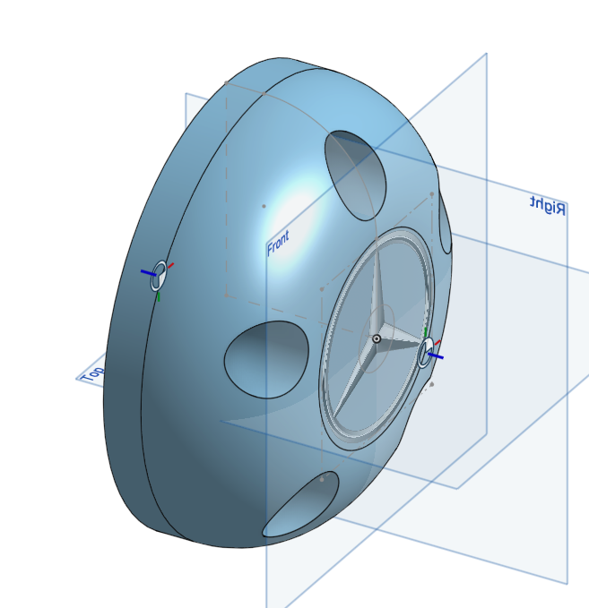
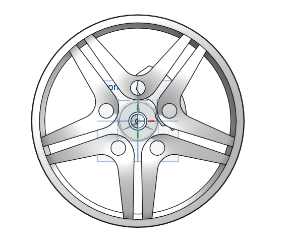
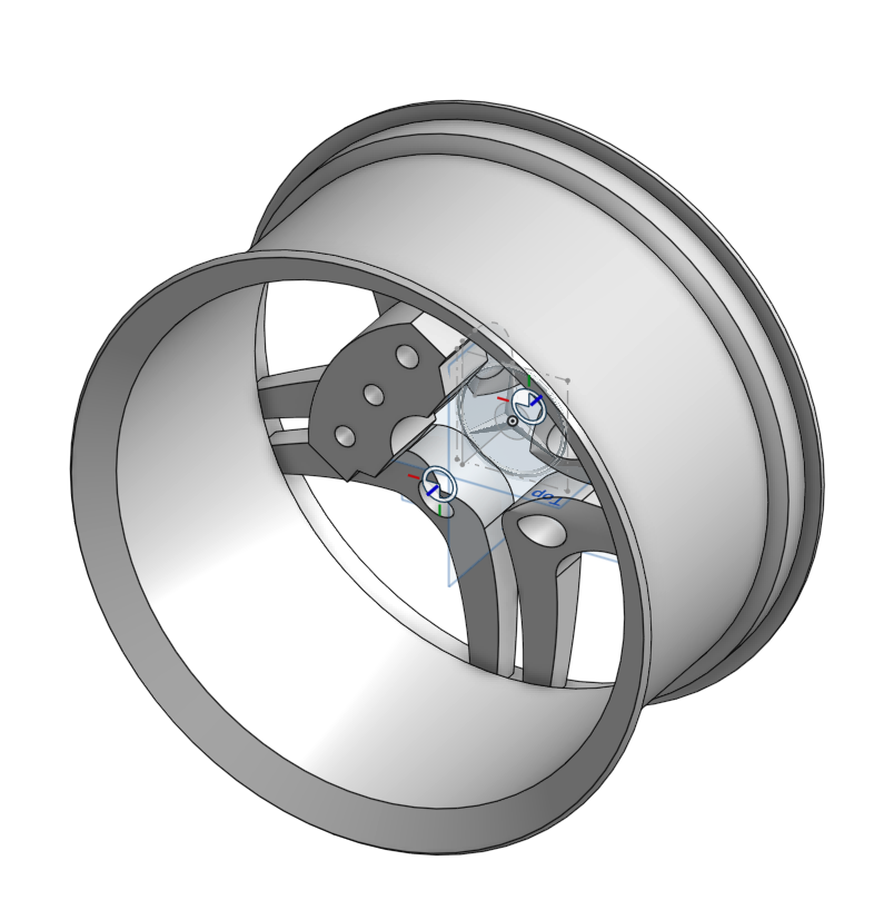
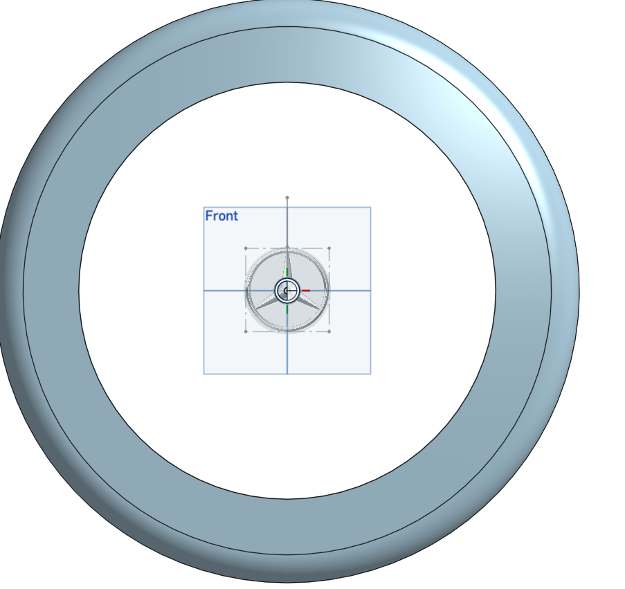
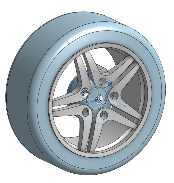
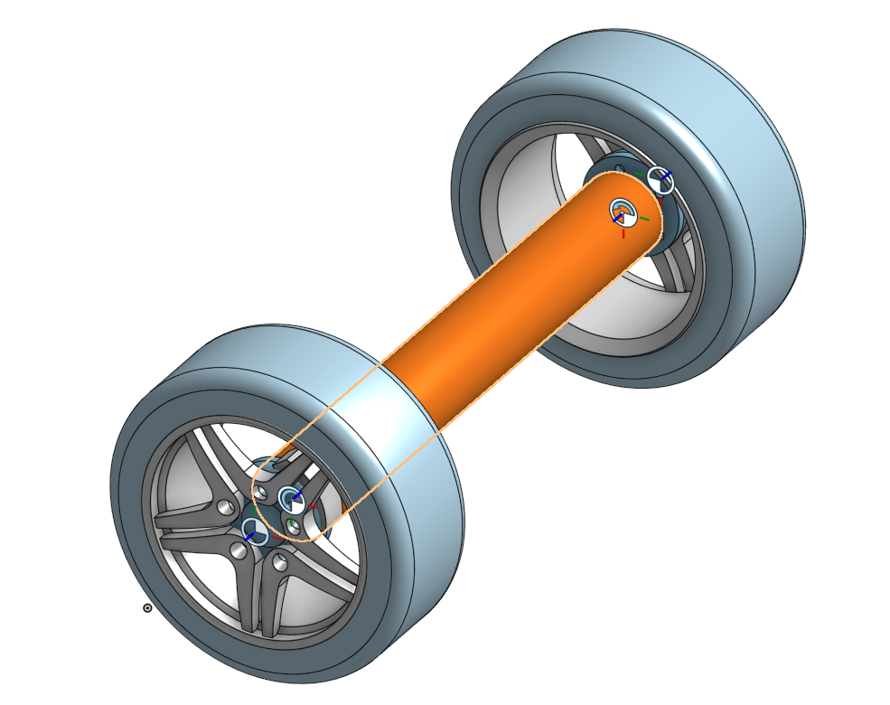
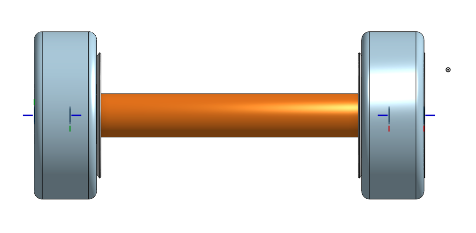
Assembled view:
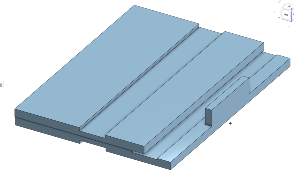
Isometric
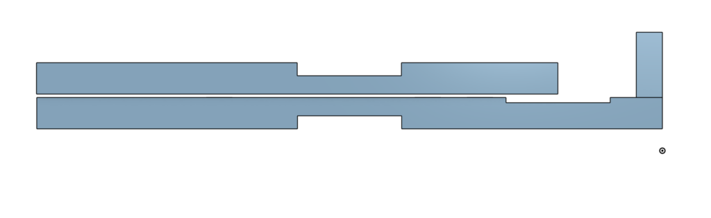
Side view
I haven’t added the block or hinges yet, those are next.
The CAD makes it easier to see how the block will fit when folded and where the hinges go. Adding the recess was important to keep the whole thing slim when folded.
Challenges I Foresee
- Getting the folded thickness to stay under 4 cm including hinges, block, and small gaps add up fast; might have to try 10 mm plywood.
- Block pivot: Drilling the hole straight through the top panel and lining it up with the block so it moves smooth without wobbling.
- Cutting the slots exactly 5 mm deep and 4 cm wide in real wood need to be careful with the router or chisel so it doesn’t splinter or go uneven.
- Hinge recess: Cutting 1.5–2 mm deep pockets exactly so the hinges sit flat (too deep = weak spot, too shallow = bump).
- Sourcing: Birch plywood is easy to find in Calgary, but if I want to switch to bamboo later, it might be harder to get or cost more.
Next Steps
- Finish the CAD: Add the support block (3.3 cm wide, 7 cm deep, 10 mm thick, centered, 3 cm from back edge) and the axle hole; add the tilting hinges (2–3 small butt hinges, recessed).
- Cardboard prototype: Cut base (32×24 cm) and top (32×20 cm) from cardboard, tape the hinge lines, cut the 4-5 slots (4 cm wide, 5 mm deep, centered), make a fake block, and test the tilt and stability with my laptop or some weight.
- Source materials: BOM