For this project, I designed a wheel assembly in Onshape as part of a CAD assignment.
For my design, I am modeling realistic car wheels and an axle, but simplified for this project. It is not a full car or engine just the wheel system. The assembly includes a center disc, wheel rim with brake disc, tire, and axle, and later I copied the wheel to put two wheels on the same axle, allowing me to test rotation of the wheel. The parts should fit together logically, look realistic, and spin properly in the assembly, but they don’t need to handle real forces or loads.
PT1: CENTER DISC
The first part I designed was the center disc, a circular cover that fits into the center opening of the wheel rim.
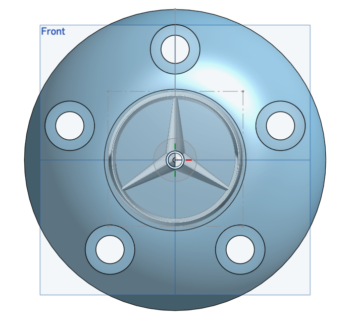
–The circular shape of the disc with a slight dome.
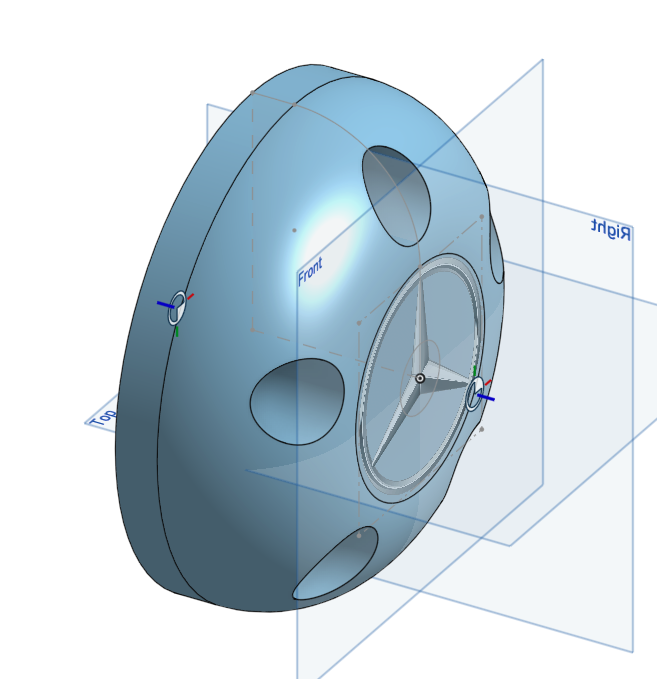
–An isometric view of the disc.
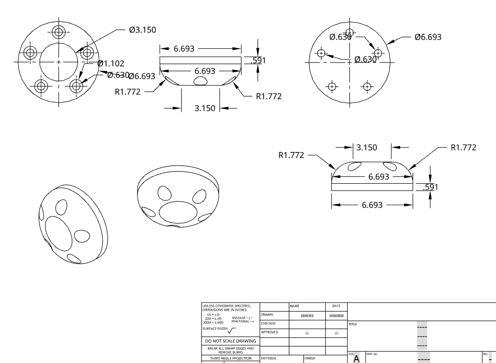
–Mechanical drawing of the disc.
The center cap disc works well and fits properly, but it’s a bit small compared to the rest of the wheel. Making it larger would help it fill the hub better and make the wheel look more balanced overall. A slightly bigger disc would also be stronger for 3D printing, because thin edges can easily break or warp during printing or handling.
PT2: WHEEL RIM
The second part I designed was the wheel rim, which serves as the main structural component of the wheel, and the brake disc, positioned inside the rim near the hub.
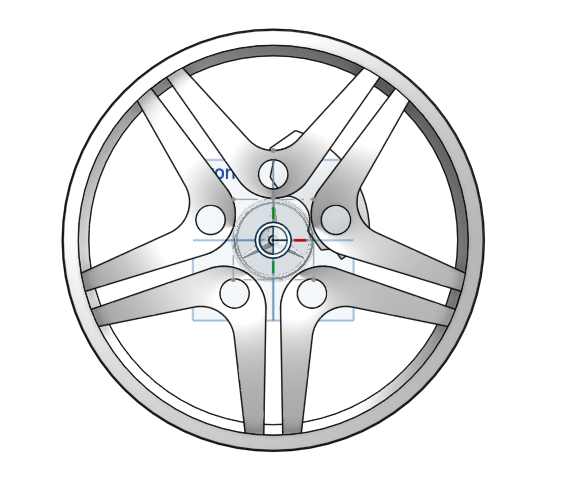
–The front view of the wheel rim showing the design and the brake.
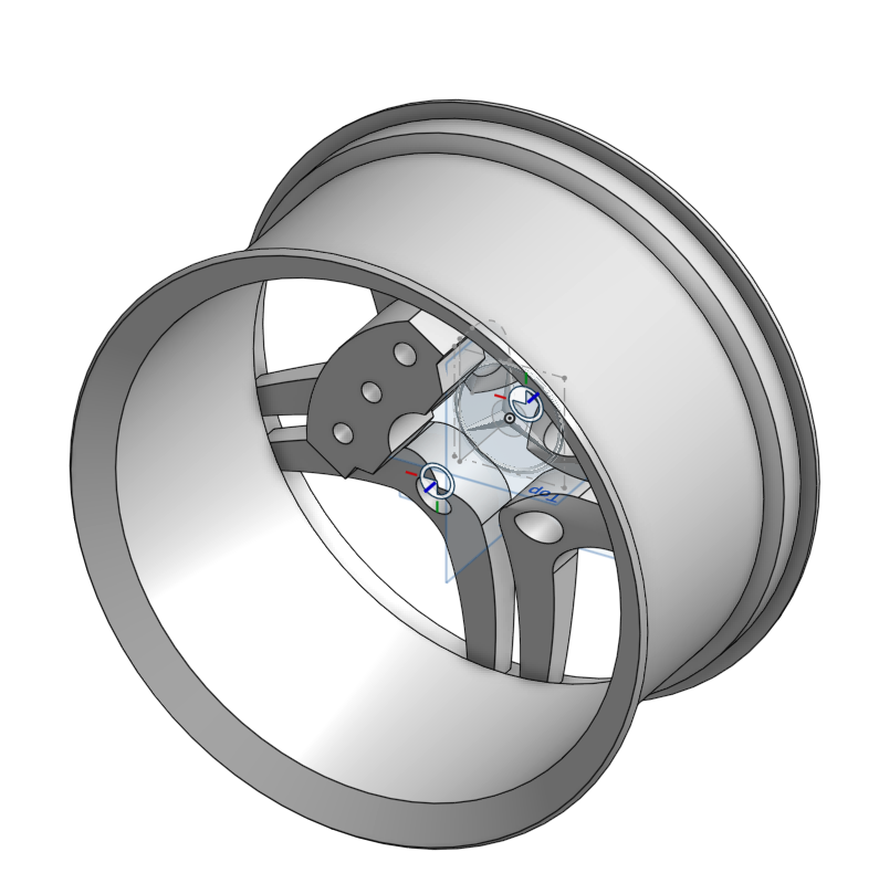
–The isometric view of the wheel rim, and this angle clearly shows the brake inside the rim.
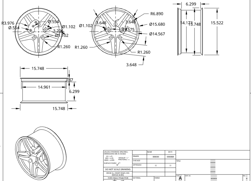
–The mechanical drawing of the wheel rim.
The wheel rim and brake came out looking pretty solid, and they fit together well in the assembly. I like how the cutouts make the rim look realistic, but I think the spacing could be adjusted a bit to make it feel stronger and more balanced. The brake disc lines up nicely with the hub, but it might look better if it were slightly thicker to match the proportions of the rim.
PT3: TIRE
The third part I designed was the tire, which wraps around the wheel rim and provides the interface between the wheel and the ground.
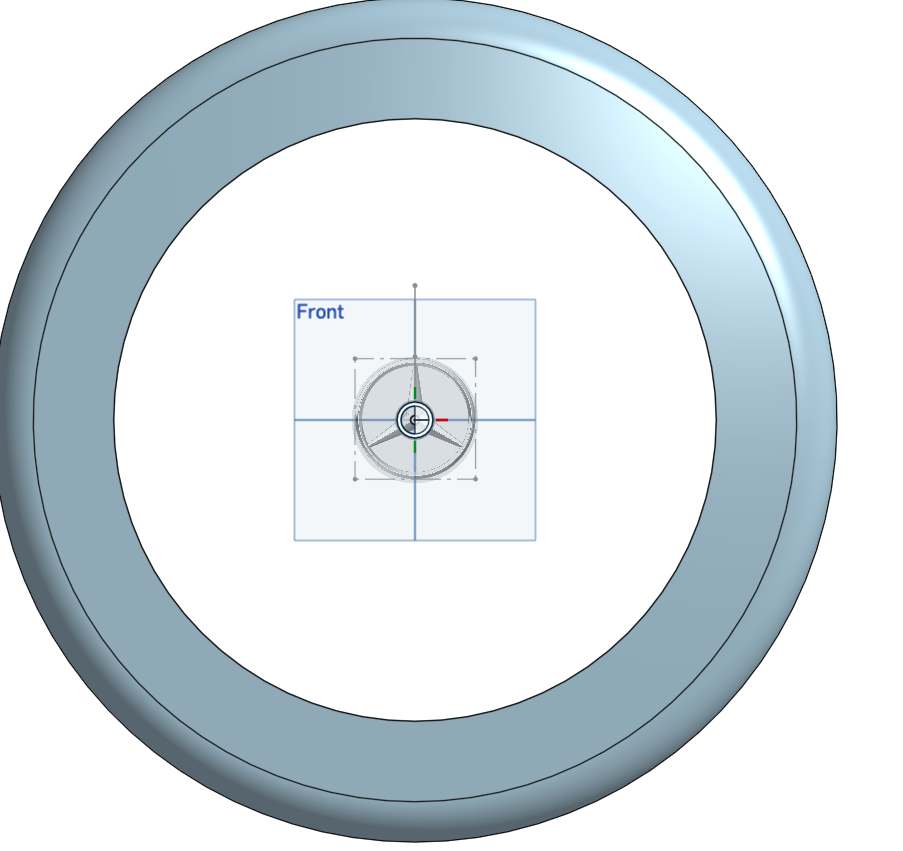
–The front view of the tire.
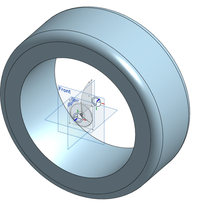
–The isometric view of the tire.
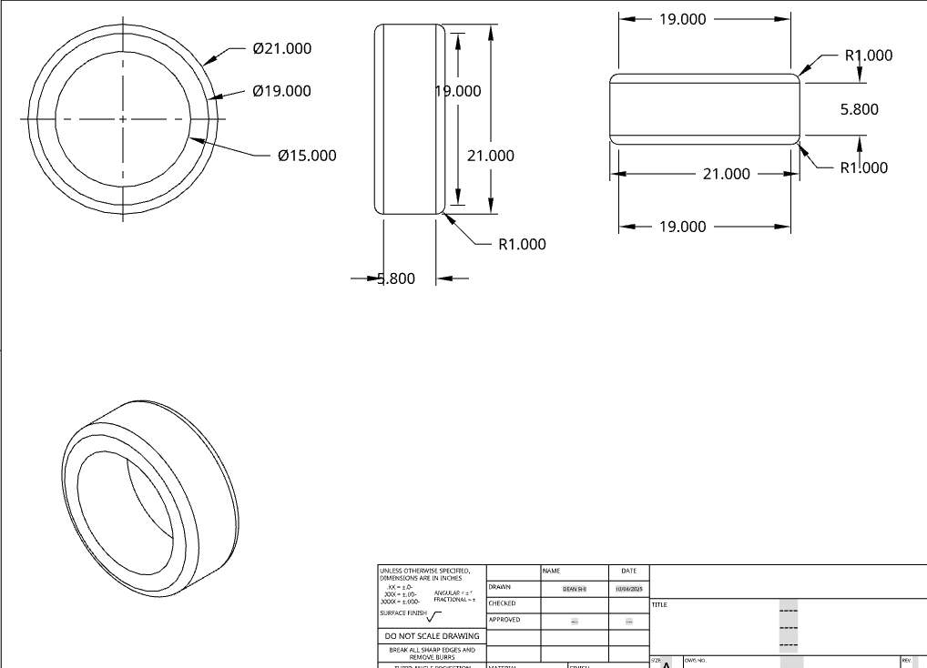
–The mechanical drawing of the tire.
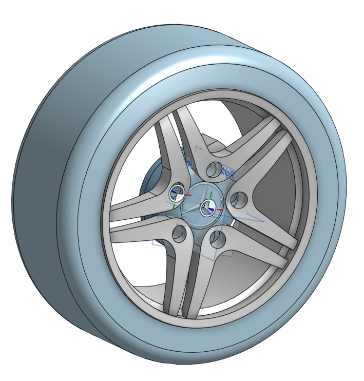
Putting everything we have so far together…
PT4: AXLE
The final part I designed was the axle, which passes through the center of the wheel and connects the assembly to the rest of the mechanism.
–Side view of the axle.
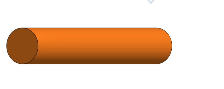
–Isometric view of the axle.
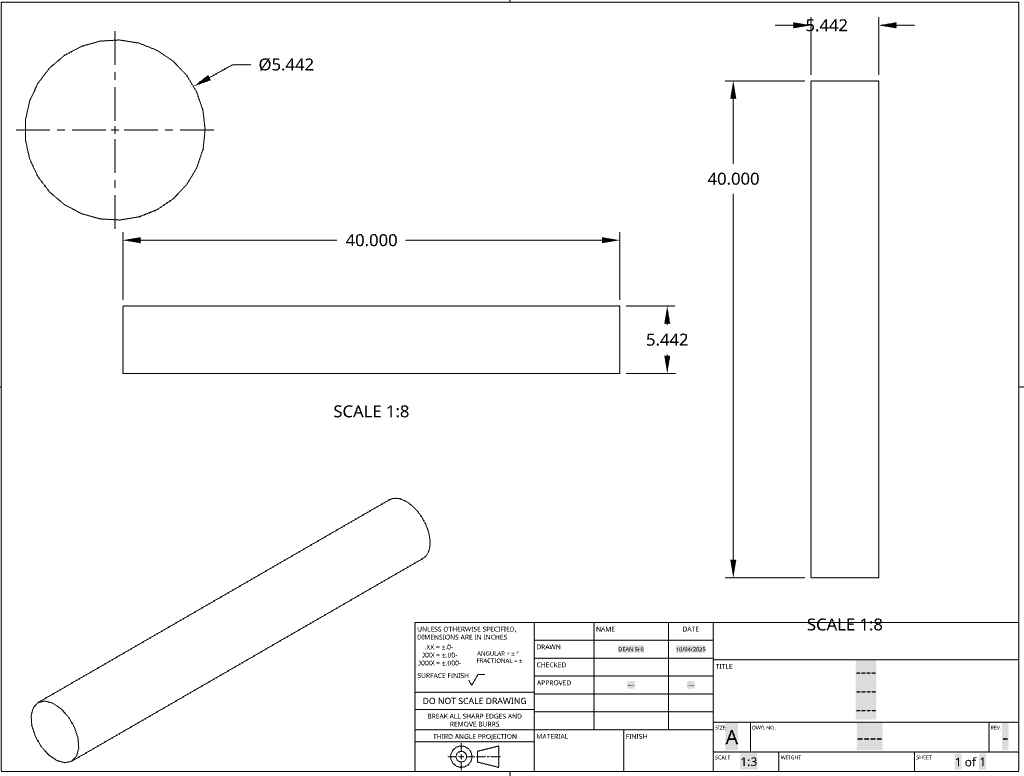
–The mechanical drawing of the axle.
The axle functions well and holds the wheel together properly, but it feels a little long compared to the rest of the assembly. Shortening it slightly could make the overall design look cleaner and more compact. The step-downs help with alignment, but maybe adding some small grooves or visual details could make it look more realistic.
PT5: ASSEMBLY
The assembly combines all the components: center disc, wheel rim with brake, tire, and axle. After completing the first wheel, I duplicated it so that there are two wheels on the same axle
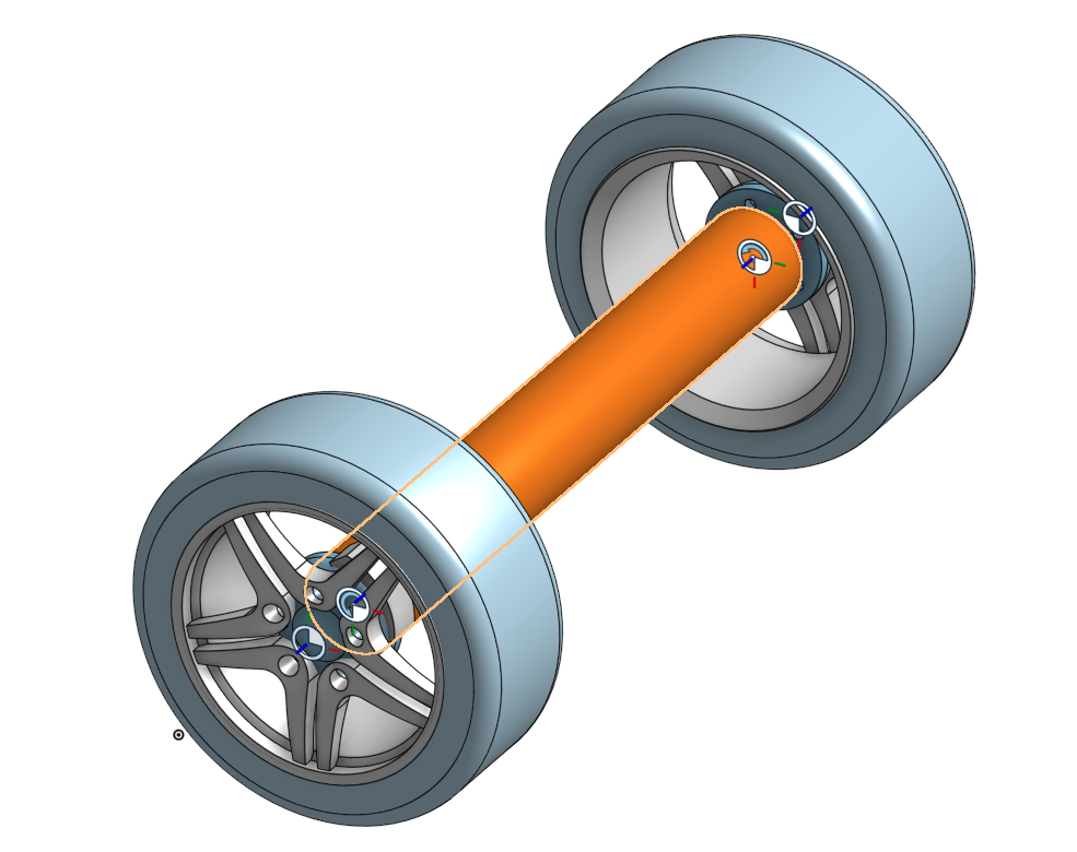
–The axle passes through the hubs of both wheels, keeping them aligned and in position.
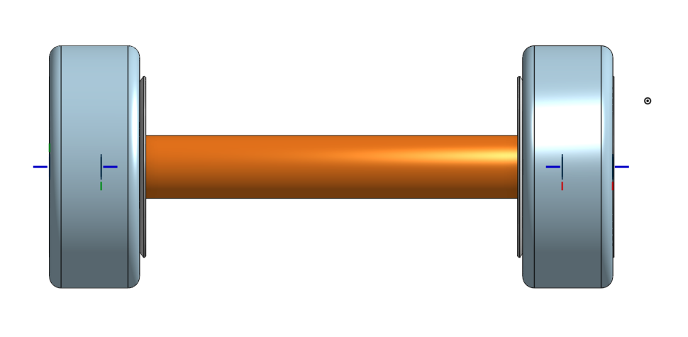
The two wheels are spaced evenly on the axle, allowing proper rotation without interference.
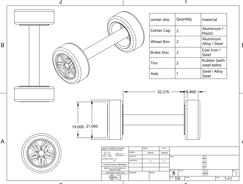
–Mechanical drawing of the assembly
The assembly turned out really well, wheels spin smoothly, everything fits neatly, and the design looks solid. Duplicating the wheel was simple but effective, and seeing them rotate together makes the assembly feel complete and polished.
PT6: CONCLUSION
The wheel project turned out really well. Each part, the center disc, wheel rim with brake, tire, and axle, they fit together neatly, and duplicating the wheel to create two on the same axle works smoothly. The wheels rotate properly, and the assembly demonstrates how all the components interact in a functional system. While some details, like the size of the center disc or spacing of the rim cutouts, could be improved, the overall design is realistic, balanced, and visually appealing. This project allowed me to practice all core CAD skills such as sketching, extruding, assembling, creating mechanical drawings, and generating a BOM.
Leave a Reply