This project intends to demonstrate the basics of robotics through the use of Arduino. I was really interested in the Geneva Drive mechanism, so I decided to base my project around it.
I designed a display stand that can rotate to show four different things. However, a constantly rotating display stand would make it hard to see each thing clearly. By using a Geneva drive, I can transform a constant turning motion into separate 90° turns with pauses in between. Additionally, I added LEDs to light up each display item with a different colour and set them up to match the rotations of the display.
I selected four Lego Ninjago Minifigures to put on the display as Lego Ninjago is one of my favourite tv show and an integral part of my childhood.
Video Demo
https://drive.google.com/file/d/1XJ2-KDv5k0xWASW0IL4BOMyf_LY_ffpl/view
Virtual Prototype
◈ Onshape Design
Geneva Drive Mechanism Demo
Geneva Drive Mechanism (Driven Wheel, Driving Wheel, and Wheel Guide)
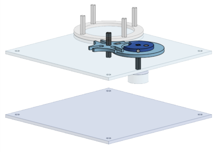
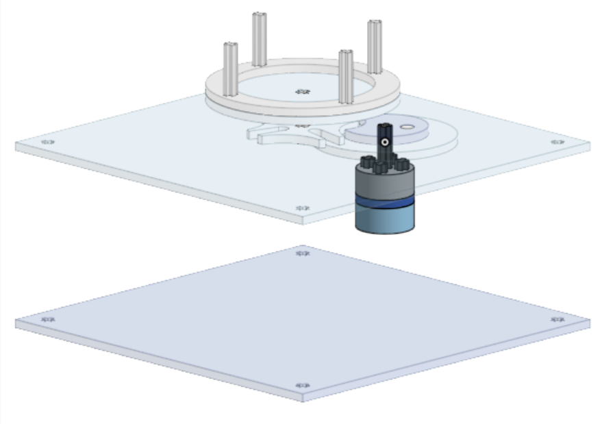
Motor Adapter and Connector to Driving Wheel and Wheel Guide
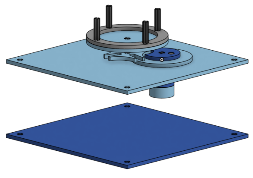
Display Stand and Connector to Driven Wheel
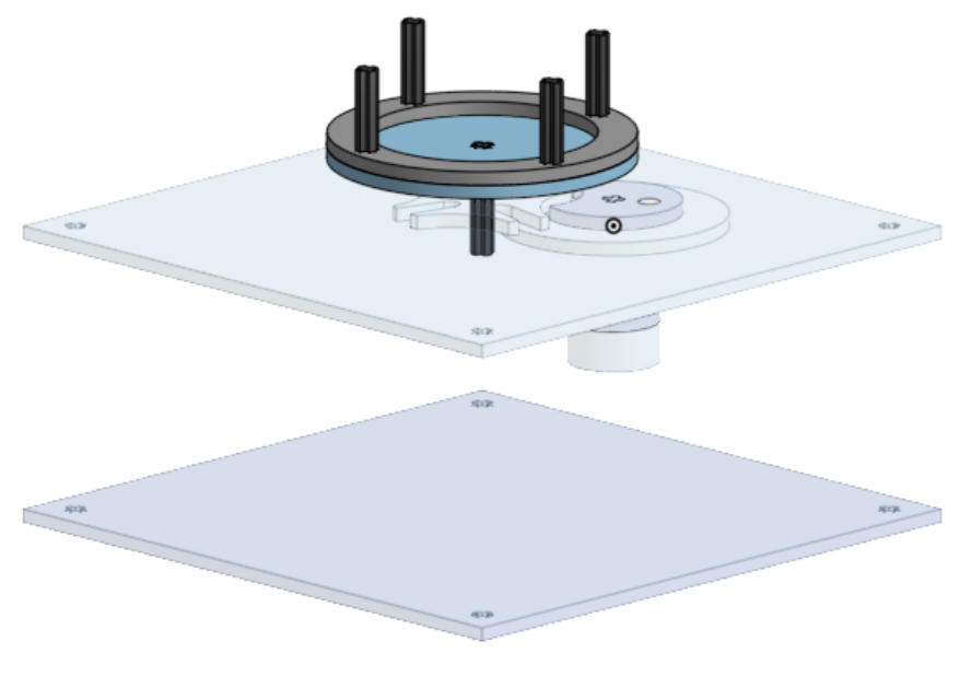
Full Assembly
◈ Circuit Schematic
TinkerCAD Circuit
Auto-Generated TinkerCAD Circuit Schematic
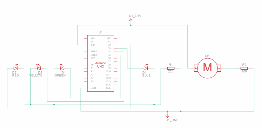
The Motor is connected to a 3.3V and a different grounded resistor. I tested many different resistance values to find a suitable rotation speed and landed with a 10Ω resistor.
The 4 LEDs are each connected to a different Arduino Pin (D2 to D5) and then to the same grounded resistor (220Ω).
◈ Bill of Materials (BOM)
Auto-Generated TinkerCAD Bill of Materials
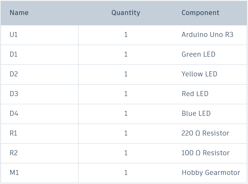
I also need many wires and a breadboard to connect these components.
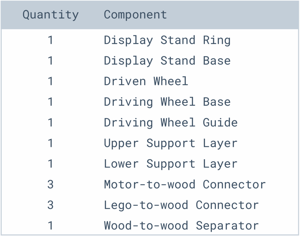
Laser-cut pieces
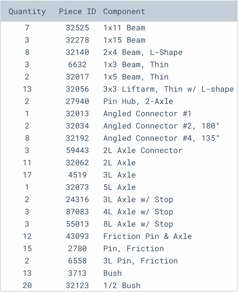
Lego pieces
◈ Arduino Code
const int PINS[] = {2, 3, 4, 5};
const int RPM = 30;
const int DELAYMS = 60000 / RPM;
int idx = 3;

void setup() {
  for (int pin : PINS) {
    pinMode(pin, OUTPUT);
    digitalWrite(pin, LOW);
  }
  // Serial.begin(9600);
}

void loop() {
  digitalWrite(PINS[idx], LOW);
  idx = (idx + 1) % 4;
  digitalWrite(PINS[idx], HIGH);
  delay(DELAYMS);
}
I included 3 constants in my code:
- “PINS” is an array that stores which pins are connected to the LEDs.
- “RPM” is a constant that stores how many rotations per minute the motor spins.
- “DELAYMS” is the number of milliseconds per revolution given the RPM.
The “setup” function runs on start, sets pins 2 through 5 to OUTPUT pin mode, and turns them off.
The “loop” function loops continuously and turns off the previous light and turns on the next light. “loop” will repeat once every revolution.
Physical Prototype
◈ From Virtual to Physical
My virtual prototype did not account for gravity. In the physical prototype, many of the axles were wobbling and leaning to the sides. To fix this issue, I added many support structures to stabilize the axles.
To keep the entire Arduino system within the physical base, I used a separate battery source to power the Arduino, rather than connecting to my computer.
My virtual prototype lacked a switch to control the motor. It was annoying to have to take out and put back the wires to control the motor, so I decided to connect a switch between the 3.3V source and motor.
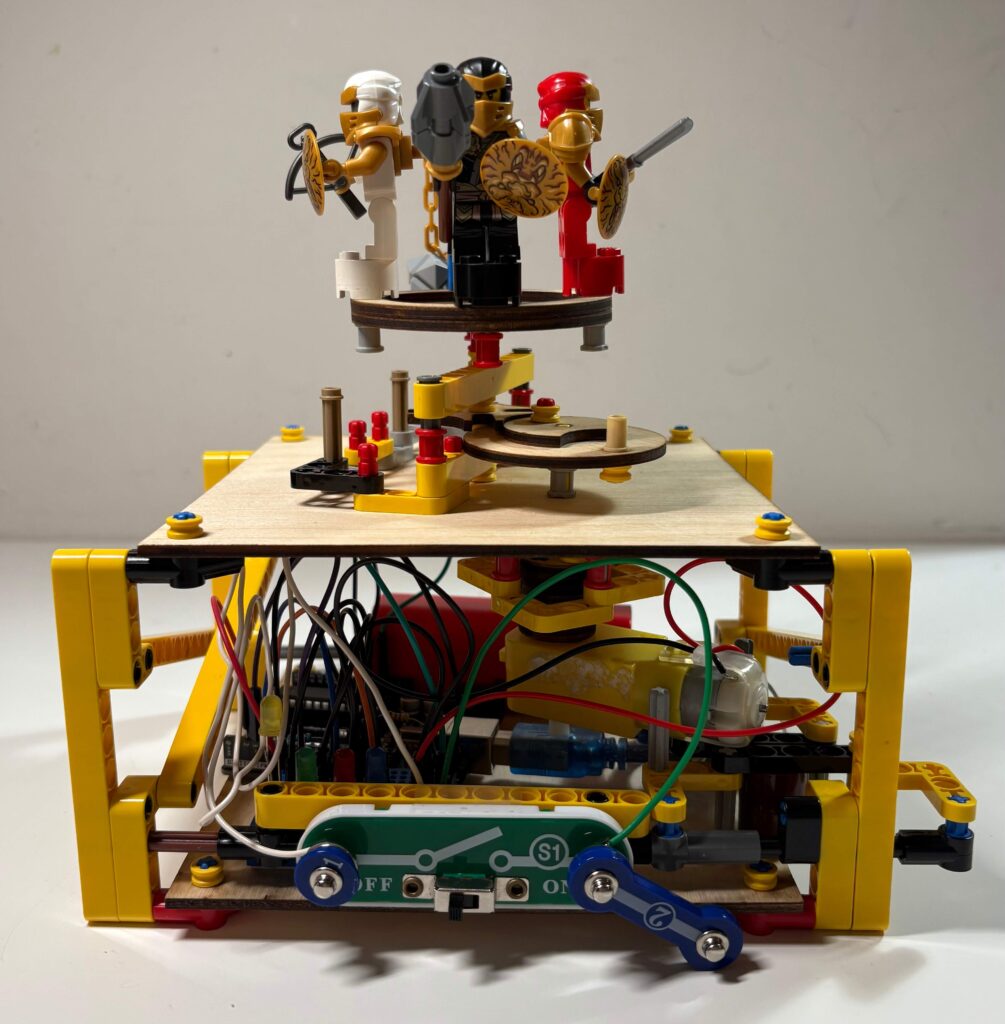
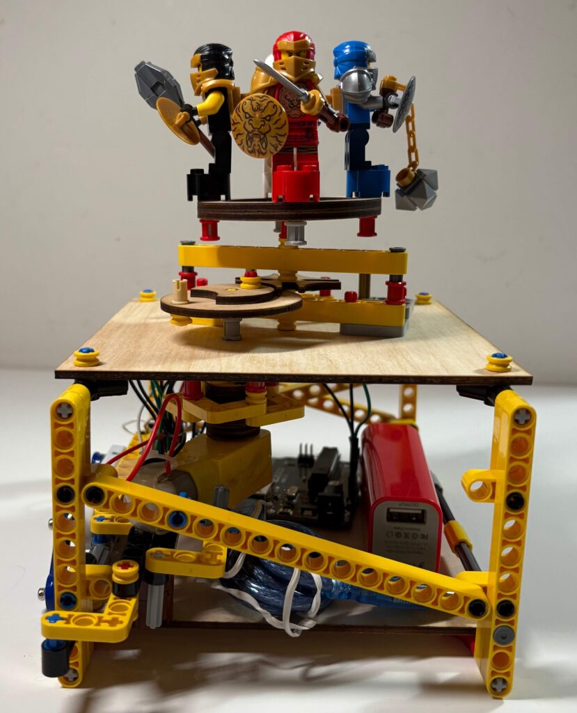
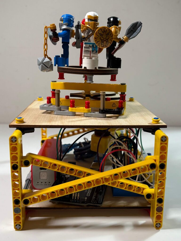
◈ Photos
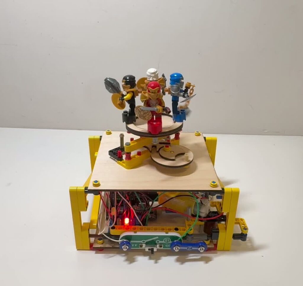
Rotating Display System From Four Sides
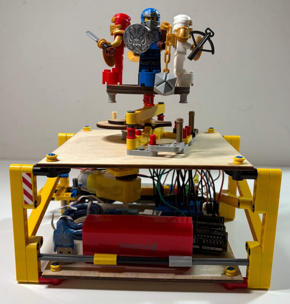
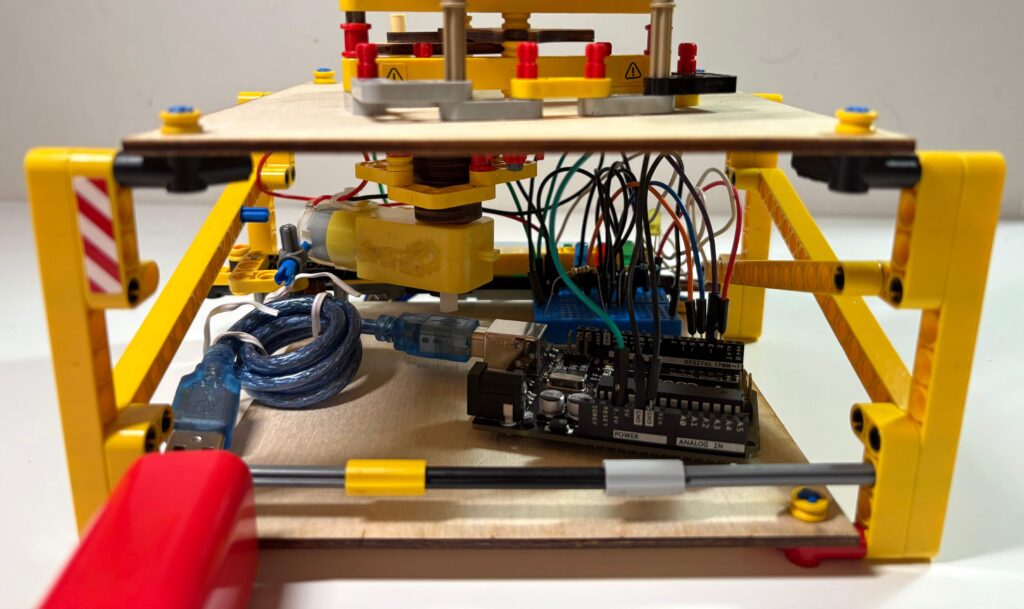
Close-up Inner Assembly (Breadboard, Arduino, Battery, Motor, Wiring)
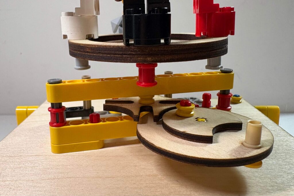
Close-up Geneva Drive Mechanism
AI Usage
As I had some experience with robotics already, I did not need to use AI to learn robotics.
Revision
This is my revised design of circuit that allows the arduino to control the starting and stopping of the motor that rotates my display.
◈ Circuit Schematic
TinkerCAD Circuit
Auto-Generated TinkerCAD Circuit Schematic
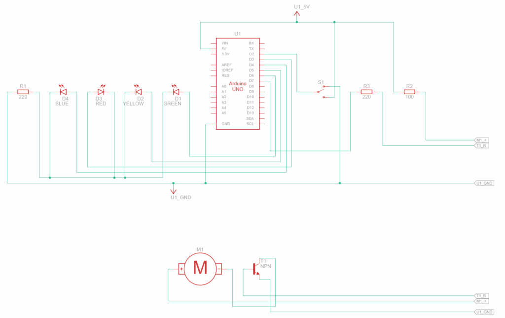
I added an NPN transistor to control the motor, and a slideswitch to get user input.
The Motor is connected to the collector pin of the NPN transistor and a 5V power source through a resistor.
The NPN transistor’s emitter pin is connected to ground and its base pin is connected to Arduino Pin 7 through a 220Ω resistor. This allows the Arduino to control when the motor is “on” or “off” through Arduion Pin 7.
The slideswitch is connected to power, ground, and Arduino Pin 2, which is in “input_pullup” mode to read the user’s slideswitch input.
◈ Bill of Materials (BOM)
Auto-Generated TinkerCAD Bill of Materials
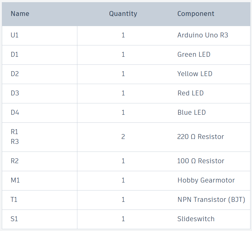
I also need many wires and a breadboard to connect these components.
◈ Arduino Code
const int PINS[] = {3, 4, 5, 6};
const int PIN_M = 7;
const int PIN_S = 2;
const int RPM = 30;
const int eps = 53;
const int DELAYMS = 60000 / RPM - eps;
int idx = 0;

void setup() {
  for (int pin : PINS) {
    pinMode(pin, OUTPUT);
    digitalWrite(pin, LOW);
  }
  pinMode(PIN_M, OUTPUT);
  digitalWrite(PIN_M, LOW);
  pinMode(PIN_S, INPUT_PULLUP);
}

void loop() {
  if (digitalRead(PIN_S) != 1) {
    digitalWrite(PINS[idx], HIGH);
    digitalWrite(PIN_M, HIGH);
    delay(DELAYMS);
    digitalWrite(PINS[idx], LOW);
    digitalWrite(PIN_M, LOW);
    idx = (idx + 1) % 4;
    delay(1000);
  } else {
    delay(100);
  }
}
I added 3 new constants in my code to control the motor:
- “PIN_M” is a constant that stores which pin controls the motor.
- “PIN_S” is a constant that stores which pin reads the slideswitch input.
- “eps” is a constant that adjusts for rotation error. The motor spins at RPM rotations per minute but turning it off after DELAYMS milliseconds isn’t perfect, so we use “eps” to fix it.
I changed the “setup” function accordingly with the 2 new pins.
I also added slideswitch input handling (if statement) and motor on/off control (digitalWrite(PIN_M)) to the “loop” function.
Additionally, I added a short 1 second delay to increase the pause between each rotation. In turn, this makes each side of the display stop for a longer time.
Leave a Reply to astonw Cancel reply