Since my previous update, I’ve progressed on my project. I am trying to build a connection between a brain and a computer, and perhaps eventually the body. I define the problem below
There are 15.4 million people with spinal cord injury, which disrupts the connection between their brain and muscles. Current technology does not reliably restore intuitive voluntary movement. A system that would be able to understand what the user wants to do and stimulate their muscles would restore voluntary movement.
Since the last update, I’ve done research to better understand the potential target market to allow me to focus my project more specifically.
There are two main parts of paralysis I’m looking at: paraplegia and tetraplegia. Paraplegia is the paralysis of the legs while tetraplegia is the paralysis of all 4 limbs and the torso.
I have decided I will start as simple as possible. My procedure is as follows: Use the BCI CV 2a Dataset to train a classification model that gets a minimum 95% accuracy score. Then, I will purchase an affordable EEG headset. I will need to make a new model based off the previous one for the specifications of the new headset.
The main part of the definition statement this focuses on is “understand what the user wants to do.” That part is much safer to focus on because once the human body gets involved, I am at risk of harming someone, for example if I tested it on myself(which I probably would), I might damage something in my body.
The biggest challenge I foresee is coding the classification model because it has been some time since I’ve done any big coding projects, so it might take some time for me to remember.
As of right now, my next step is to create the classifier model.
I have used AI to assist me in my project to help me unpack such a complex topic. The transcripts are listed below:
There are 15.4 million people with spinal cord injury, which disrupts the connection between their brain and muscles. Current technology does not reliably restore intuitive voluntary movement. A system that would be able to understand what the user wants to do and stimulate their muscles would restore voluntary movement.
I am solving this problem for the 15.4 million people who deal with spinal cord injury today. There are two main types of SCI: Tetraplegia which is paralysis of all 4 limbs and some of the torso, and paraplegia where the legs cannot move but the arms still work. I will. specifically focus on helping people with Cervical SCI to help restore upper-limb movement.
Possible Solutions
Noninvasive BCIs connected to electrodes to externally stimulate muscle contraction
This idea is the best for my current position. I do not have access to a lab to implant electrodes and BCIs. Noninvasive BCIs are not as powerful because of the noise that they pick up alongside the brain activity. However, using AI I will be able to remove some noise to detect brain intent.
Invasive BCIs connected to electrodes to stimulate muscle contraction
Although this idea would be much more powerful than the previous, I do not have access to a lab where I could implant an invasive BCI, nor do I have the license to.
Electrodes on the spine to restore connection between brain and muscles
This idea would also require a lab to insert the electrodes on the spine, which is not feasible in my position. However, this idea could potentially be more powerful than idea #2 because instead of getting signals directly from the brain and externally stimulating the muscles, this would theoretically restore the original movement because it is the link between the brain and the muscles.
Implant electrodes inside muscle tissue to make precise movement connected with BCIs
This is not so much of a standalone idea as something to add on to another idea because implanting electrodes in the muscles to get more precise movement would be much better when retraining motor control to help restore fine movements.
BCI controlled exoskeleton
A BCI controlled exoskeleton although it would be simpler than stimulating the muscles, it is bulky and the goal of the BCI solution is to make something discreet to make the people who suffer from SCIs feel more normal.
Possible Prototype for #1
The prototype would be a non-invasive BCI to get signals from the brain. Because the brain still sends the same signals to the body even when they can’t move the body parts, those signals can be read to send signals to different electrodes placed on the body. When the electrodes send a small electrical pulse, the muscle contracts.
What I hope to have ready in May at the minimum is a noninvasive BCI that I can read the signals from to determine some sort of action the user would like to do. Depending on how much progress I make I could either show the results on the computer and make the user do something such as play a simple game like flappy bird/dinosaur jump, or I could connect it to electrodes on my muscles to stimulate them, if I am allowed.
Plan for this Project
The first step of this project is understanding software. I will use an EEG dataset to make a classification algorithm to classify motor intent. Then I will simulate it to see if it works and iterate.
Once I have a working algorithm, I will purchase a noninvasive EEG and use the algorithm to decode the signals from my brain. I will attempt decoding starting at simple left and right imagery, then go into more complex commands and see how good my algorithm is. I will iterate with the algorithm until it is strong enough to use.
After this I will purchase an electrode to attempt stimulating my muscle. I will need to be very careful at this stage because doing it wrong could cause harm to the wearer, which would be me. I may decide not to use an electrode but instead use the signal to send signal to a robot arm, which would move based on the commands.
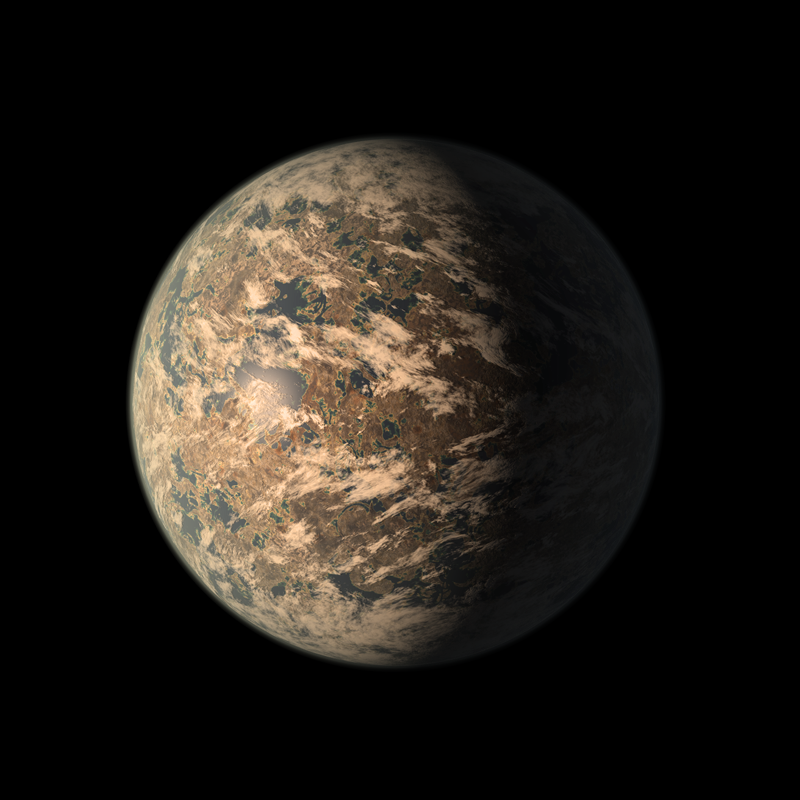
TRAPPIST-1e is one of Earth’s best opportunities for a home beyond Earth. It is a rocky planet with a density very similar to Earth, located about 40 light years away from Earth. Because of the distance from the planet to its star, TRAPPIST-1, it lies in an area called the Habitable Zone. This zone is special because it means there is a higher likelihood of liquid water being present on the planet.
In order to take advantage of this we must build a vehicle to travel through the planet. So we narrowed down the project into one statement.
The Definition Statement
We need to build a vehicle that can withstand TRAPPIST-1e’s extreme contrasting temperatures, traverse the uneven and rocky terrain, and endure the immense radiation emitted by TRAPPIST-1e’s star. Additionally, the vehicle must be large enough to hold at least four individuals and have enough fuel to travel 10km, unless powered by another source such as advanced radiation solar power.
We spent a few days looking over this idea in order to decide how we would go about this process. We focused on one main part of this prompt that is possible to test in Earth’s atmosphere: uneven rocky terrain.
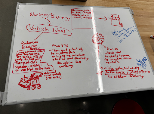
Below is our whiteboard where we drafted many ideas for our vehicle.
Radiation Powered Rover
We thought of harnessing TRAPPIST-1’s powerful radiation with special solar panels in order to power the vehicle. We identified the problem that the atmosphere of TRAPPIST-1e would significantly reduce the radiation.
Rocker-Bogie System
We saw on the Mars rover, they use a special suspension called the Rocker-Bogie system, which is very good at climbing tall hills and uneven surfaces.
Traction Wheels
We decided to use traction wheels in order to have a strong grip on the rocky, uneven terrain our vehicle would have to drive on during its voyages.
Method / Procedure:
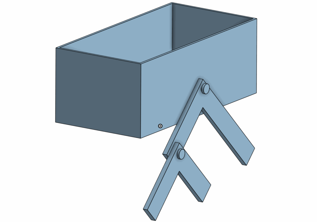
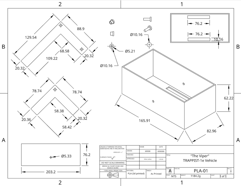
Once we had imagined our vehicle, we started to make the CAD design for it. We went through several designs and iterations before we had figured out what design we would use.
This is what our final product looked like with only one of the rocker-bogie parts on. Normally there is one on both sides. There are four main parts to this:
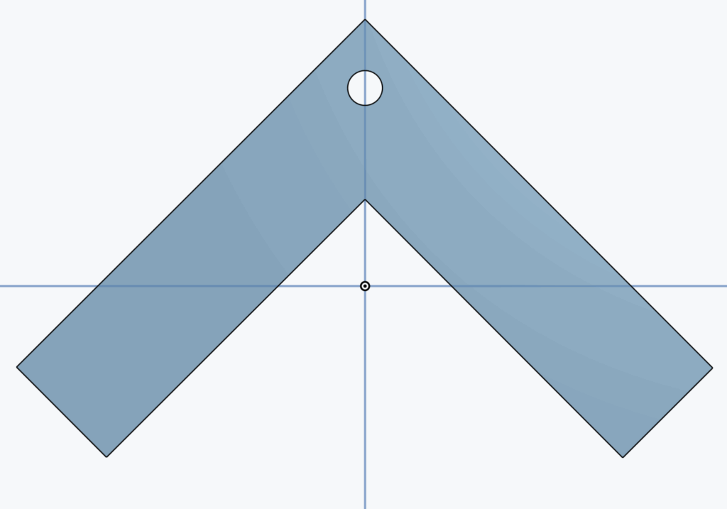
The Rocker
The Bogie
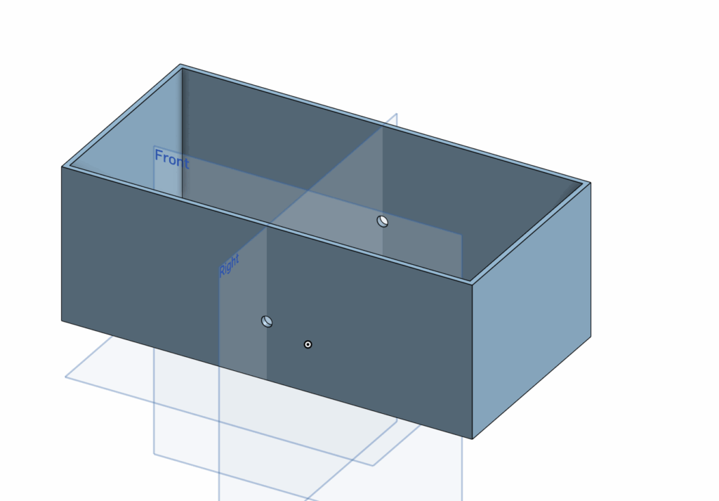
The Body
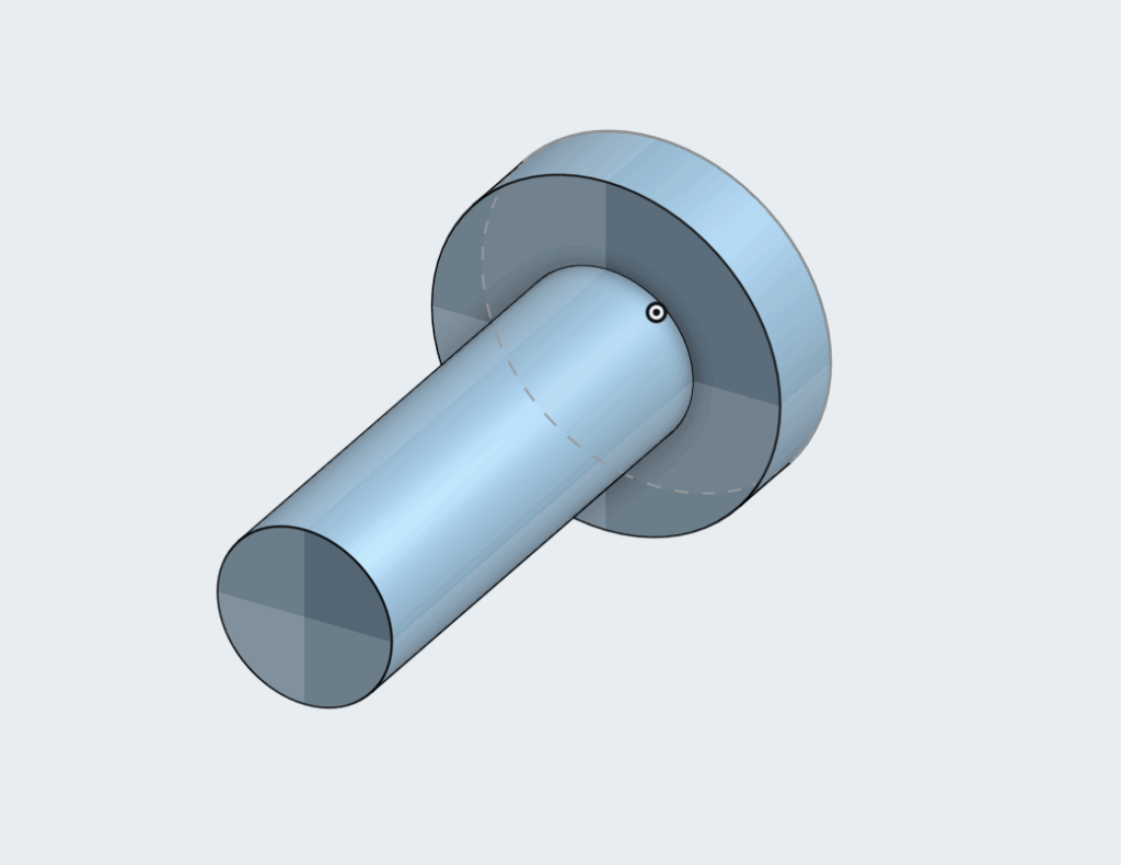
The Screws
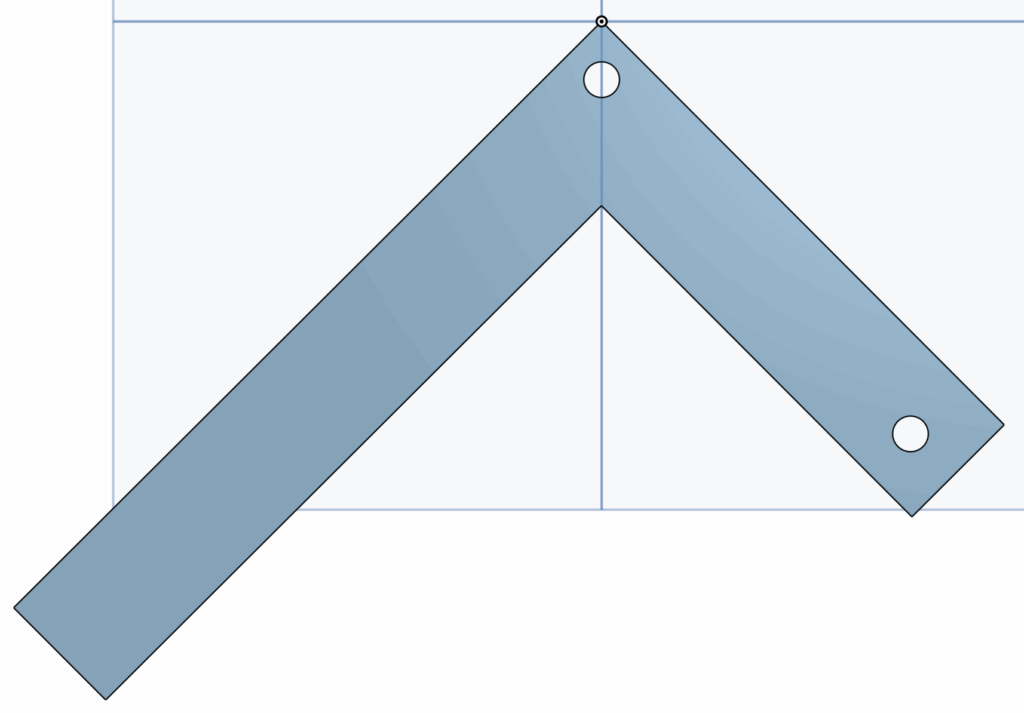
The Rocker is the larger piece and it connects to the body with a central pivot point to allow the vehicle to rotate up and down over the rocks.
The Bogie arm is the smaller part of the mechanism and it is connected by the hole on the top to the Rocker arm. It stays in the rear and its job is to keep the wheels in contact with the ground as much as possible to maintain consistent movement.
The body is made with two holes that, if you look straight at the vehicle from the side, you will see is right in the middle. This is because we want the body to stay stabilized upwards and by keeping the hole high up and in the middle, it keeps the people inside safe, while the Rocker-Bogie suspension still does all the work.
The screws were made specially to fit exactly into our holes we made in the body and the arms. We used custom screws to make sure the arms wouldn’t have difficulty rotating.
However, while we were making all these parts for the CAD, we went through many iterations and failures. We spent a long time thinking about measurements and lengths of the arms. Using Onshape was a process of trial and error because we still didn’t fully understand everything, especially assembly at the end.
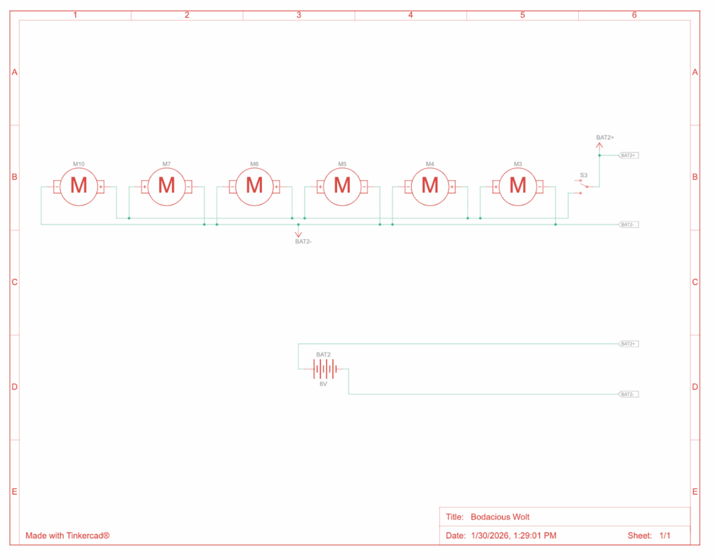
We made a diagram for the circuitry to make sure building everything would be as fast as possible as soon as the materials came.
We made an official circuit diagram to show connectivity between each component.
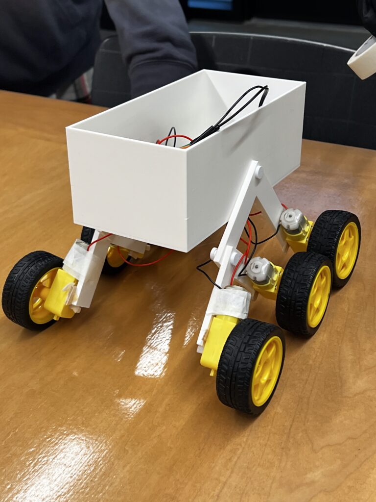
We also purchased 6 motors and 6 wheels to let the vehicle actually move, and glued them onto each end of the arms, 3 on each side. We connected everything with a breadboard attached to some batteries. The process of building everything was very efficient once we had all the parts we needed.
We were very proud to finally have built the car. However, in engineering building the contraption is only half the work. One of the most important parts is testing.
Testing / Data:
The first “test” we ran was immediately after we had built the vehicle. We were happy to see it drive well on flat ground. It drove pretty straight and at a consistent speed.
Next we decided to test it on bumpy terrain by putting some thick pieces of styrofoam on the floor and let it drive through them. We noticed that it had trouble doing this because the distance between the wheels wasn’t big enough for it to fully go over with the Rocker-Bogie mechanism. We learnt that it had a limit, it could go over smaller bumps, but it had difficulty with big ones.
Once we were satisfied that our vehicle could drive, we began the real testing.
Test #1: Rocky Surface
Our first test we planned to do over gravel in order to mimic the terrain that TRAPPIST-1e would have. The goal of the test was to see how efficient the vehicle was on an uneven surface. We used a multimeter to measure voltage before and after and current during the test. We also measured the distance travelled and the time it took.
The vehicle did well on the test and travelled on the gravel as we had wanted it to go. We had also collected all the data we needed and were happy with how we ran it.
Test #2: Smooth Surface
We wanted to see how the car would do on a flat surface to compare it to the run on gravel. This is important to determine the efficiency of the suspension we made. We made the test as similar as the previous test, the only difference being the terrain.
The vehicle did well on the test and drove in a proper straight line. We were happy with the results from this test because this meant we could calculate comparative efficiency.
Test #3: Test Day
On the final Test Day, our vehicle broke down so we were unable to test. One of the wires for a motor broke and without enough time to solder it together, we had to sit the test out.
However we had already gathered enough data to do a good analysis of our vehicle.
Analysis
The goal of this analysis is to determine the efficiency of the vehicle. Efficiency is defined as useful energy output divided by total energy input. Because of the limitations of our data, we are unable to measure useful energy output. In engineering, another concept is commonly used called traversal efficiency, which is defined as distance in meters the vehicle travelled per Joule of energy used.
The formula for electrical energy is written below.
Where V is average voltage, I is average current, and t is time. We calculated average voltage with the voltage before and after the test. Similarly, average current was calculated with the average of the current at different times during the test.
Test #1:
Test #2:
Results:
Test #1:
Test #2:
Comparative Efficiency
Based on the two tests we did, we can compare them to understand how much the obstacles affected the vehicles ability to drive.
This means that the vehicle was 72% as efficient on gravel compared to smoother terrain.
It is important to note that true efficiency in this case should be mechanical efficiency. In order to calculate this, you calculate the product of force and distance, all divided by energy input. We are unable to calculate it because it requires us to measure friction or torque. Therefore our method for calculating efficiency is much more reliable and would not rely on estimates.
Conclusion / Evaluation:
From this process, we learned how to bring an idea to life. We started small in the brainstorming stage, thinking about little details and piecing together a design prompt. Then we went to the designing stage, going through many designs of how we pictured the vehicle in our heads and putting it on the CAD. After that, we 3D printed it and put everything together. Once we did that, we went on to test the vehicle a few times to understand how good it really was.
We as a group were proud of how we performed. Our vehicle made it through almost all of our tests and had some pretty strong results. One thing that surprised me was the efficiency results. For the gravel test which was meant to simulate the real planet, we got 72% relative traversal efficiency. This is a descent result, it is 28% less efficient on uneven surfaces, showing the effect of rocky terrain.
Had we the opportunity to improve our design, first of all we would redo the CAD to increase the distance between the wheels. We learned about this issue on our second unofficial “test” where we tried driving the vehicle over thick pieces of styrofoam. The wheels would get caught against each other as it tried to drive over.
However, I think the design was still well made and I think it would work on our planet, TRAPPIST-1e. Although it is too far for us to see exactly what the terrain looks like, based on the predictions of the terrain, it is rocky and uneven. This is precisely what our vehicle is made for, which is why I think it would perform well.
To summarize the design prompt, we need to build a vehicle to survive TRAPPIST-1e’s dangerous conditions and carry 4 passengers over a distance of 10km. Our design has the potential to do all of this. It will, of course, need some larger tweaks as we scale the vehicle, but the general design our group made would perform on our planet.
Trappist-1e is one of humanity’s best candidates for a future home. It lies in Trappist-1’s habitable zone, meaning that there is a chance of liquid water, the most important factor to human survival. It’s a rocky planet approximately the same density as Earth.
Even though Trappist-1e is 39 light-years away, it has many good opportunities for humans. Because Trappist-1e has similar gravity to Earth, humans would adjust easily to the new environment. Trappist-1e and the other planets in the Trappist-1 system have a good chance of having water because they are in the habitable zone and Trappist-1e specifically has a rocky composition similar to that of Earth’s. According to the TRAPPIST-1 Habitable Atmosphere Intercomparison (THAI) project, even with many different atmosphere possibilities, Trappist-1e has a good chance of being livable, the main exception being if it has no atmosphere.
Settling on Trappist-1e has some serious challenges. The planet may be tidally locked, which would mean that one side is in constant daylight and extreme heat and the other side is in permanent darkness with extreme cold. The only habitable part would be the twilight zone. Another big problem is that we don’t know what type of atmosphere Trappist-1e has, or whether there even is an atmosphere. Based on research by JWST, Venus and Mars-like atmospheres are ruled out, however there are still a few problematic possible atmospheres. Without an atmosphere, humans would experience extreme cold and strong radiation from the Trappist-1 star, which is known to produce strong radiation that could harm people and damage equipment. Because Trappist-1 primarily produces infrared light, agriculture and energy generation would need to be redesigned to work under the low red lighting instead of the Sun’s bright rays.
The environment has a large implication on vehicle design. Even though humans would live in the twilight zone, travel to the hot and cold sides would be necessary to get resources like frozen water and metals. This implies that vehicles need temperature-control systems. Vehicles would need to be able to handle radiation flares. The atmosphere of Trappist-1e is unknown, but there is a chance that there is no atmosphere at all. If there isn’t, the vehicle must be equipped to handle travelling in an environment like this. Depending on what atmosphere, the planet has, the vehicle should be properly equipped for those conditions. Lastly, they would need to be equipped to drive the probably rugged terrain of the planet.
In order to build solar-powered vehicles, the design would need to be modified to work with infrared radiation because the Trappist-1 star primarily emits infrared light. Infrared light does not have as much energy as visible light, which means stronger solar panels would be needed.
Everything we know about Trappist-1e is from telescopes and analyses. It was discovered using the transit method. The transit method works to detect exoplanets by measuring light from a star and when the light gets lower for a bit, it could mean a planet passes over it. If this happens repeatedly in a cycle, it likely means there is a planet. The Trappist-1 system was discovered by the TRAPPIST-South telescope. Later, NASA’s Spitzer telescope captured much more precise transit data which told them about all the planets, their radii, orbital period which is how long it takes for a planet to orbit its star, and that it is likely a rocky planet.
In 2018, researches such as Grimm et al. published a paper called “The nature of the TRAPPIST-1 exoplanets” documenting how they used something called TTV which stands for Transit Timing Variations to calculate the masses and densities of all Trappist-1 planets. This told us that Trappist-1e has an earth-like density and confirmed it is a rocky planet.
More recently, the James Webb telescope was used to analyze starlight passing through Trappist-1e’s atmosphere using powerful tools such as NIRSpec, NIRISS, and MIRI. These can determine what gasses are in the planet’s atmosphere. The data says that Trappist-1e likely doesn’t have a Venus or Mars-like atmosphere, however it doesn’t mean that the atmosphere is suitable for humans yet.
Lastly, there was a large climate modelling project called the THAI project(Trappist-1 Habitable Atmosphere Intercomparison). It was a community project with multiple supercomputers to run multiple GCMs(global climate models).
Trappist-1e promises a good future for humankind. If we’re lucky, Trappist-1e will be the perfect planet for human beings to settle in the future, once we figure out how to travel to it.
Reflection on AI Use
I used AI to help me research about the project and to write the APA sources list. It was very useful to learn specific things that I found harder to find by surfing the web. I also found it very easy for the APA sources because it knows how to do it.
Gillon, M., Jehin, E., Lederer, S. M., Delrez, L., de Wit, J., Burdanov, A., Van Grootel, V., Burgasser, A. J., Triaud, A. H. M. J., Opitom, C., Demory, B.-O., Sahu, D. K., Bardalez Gagliuffi, D., Magain, P., & Queloz, D. (2016). Temperate Earth-sized planets transiting a nearby ultracool dwarf star. Nature, 533, 221–224. https://doi.org/10.1038/nature17448
Gillon, M., Triaud, A. H. M. J., Demory, B.-O., et al. (2017). Seven temperate terrestrial planets around the nearby ultracool dwarf star TRAPPIST-1. Nature, 542, 456–460. https://doi.org/10.1038/nature21360
Grimm, S. L., Demory, B.-O., Gillon, M., Dorn, C., Agol, E., Bolmont, E., Delrez, L., Sestovic, M., Triaud, A. H. M. J., Turbet, M., Queloz, D., & Leconte, J. (2018). The nature of the TRAPPIST-1 exoplanets. Astronomy & Astrophysics, 613, A6. https://doi.org/10.1051/0004-6361/201732233
Fauchez, T. J., Turbet, M., Wolf, E. T., et al. (2020). The TRAPPIST-1 Habitable Atmosphere Intercomparison (THAI) Project: Motivation and overview. The Planetary Science Journal, 1(2), 17. https://doi.org/10.3847/PSJ/ab9ffd
de Wit, J., Wakeford, H. R., Lewis, N. K., et al. (2018). Atmospheric reconnaissance of the TRAPPIST-1 exoplanets with Hubble. Nature Astronomy, 2, 214–219. https://doi.org/10.1038/s41550-017-0374-z
Greene, T. P., Tamburo, P., Lustig-Yaeger, J., et al. (2023). Thermal emission from the TRAPPIST-1 system measured with JWST. The Astrophysical Journal Letters, 948(1), L6. https://doi.org/10.3847/2041-8213/acc1e5
Lustig-Yaeger, J., Grillmair, C. J., Stevenson, K. B., et al. (2023). JWST transit spectroscopy of TRAPPIST-1 c shows no evidence for a thick CO₂-rich atmosphere. Nature, 623, 71–75. https://doi.org/10.1038/s41586-023-06694-0
For this project, I built an Arduino robot that detects the proximity of an object. This robot uses sensors to understand its surroundings and gives an output. Even though there is no movement, it is still a robot because it senses its environment and acts upon it.
I built a proximity-sensing robot. It uses an ultrasonic sensor to measure how close an object is to the sensor. With this it will light up one of three LED lights.
Green if object is in a safe distance
Yellow if object is getting close
Red if object is too close
At the same time it will turn a servo to a specific direction, representing an very oversimplified way of a car backing into a parking spot.
My idea is inspired by how parking sensors warn the driver how close they are to something when parking.
Virtual Prototype
Below is a video of my virtual prototype.
The circuit uses:
A 4-pin ultrasonic sensor to measure distance through sound waves
An Arduino Uno which is the brain behind the whole mechanism
LEDs of three colours to represent distance
When the object comes closer, the Arduino calculates the distance of it by the difference between the time the sound wave is sent and when the echo is received. Then it lights up the specific LED based on the distance and turn the Servo to a specific direction.
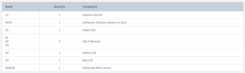
Bill of Materials
Arduino Uno R3 x1
Ultrasonic Distance Sensor (4-pin) x1
220 Ω Resistor x3
Green LED x1
Yellow LED x1
Red LED x1
Positional Micro Servo x1
Code – how does the code work?
I learned how to code using Arduino from ChatGPT. I structured my code by starting with setting the wires, then using the Ultrasonic Sensor, and then lighting up the LEDs.
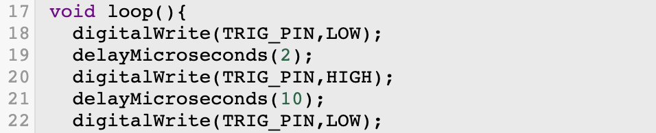
In this code snippet, the ultrasonic sensor is first set to low, then after 2 microseconds, it is set to high, then set back to low after 10 microseconds.
Here, pulseIn() measures how long it takes for the sound to travel to the object and back. 30000UL adds a timeout to make sure no errors occur. If duration==0 just restarts the code immediately if no object is detected.
This line is interesting because it turns time into distance. Sound travels at about 0.0343 cm per microsecond. It is divided by 2 because the sound goes to the object and then back.
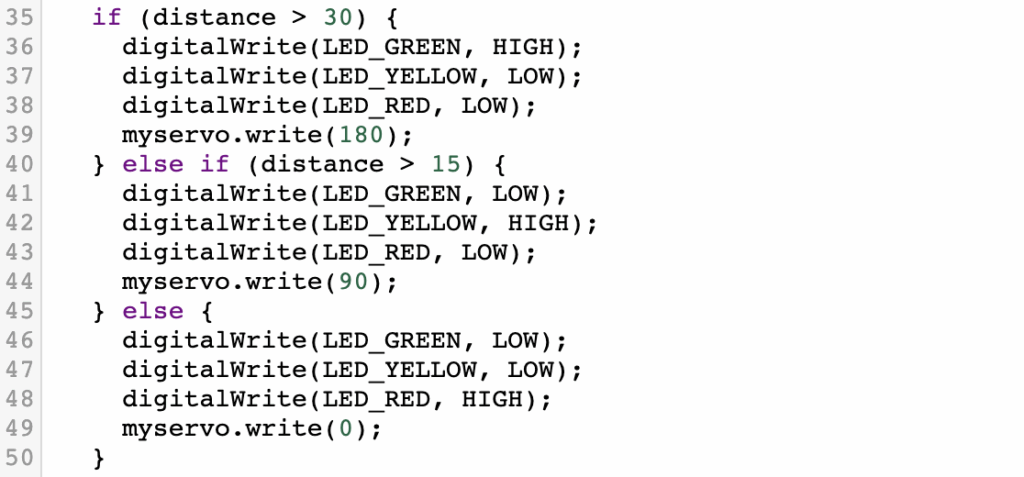
This final code snippet tells the Arduino when to turn on which LED.
Green if distance over 30cm
Yellow if distance over 15cm
Red if distance is less than that
It also will turn the Servo to a rotation based on the distance to the object.
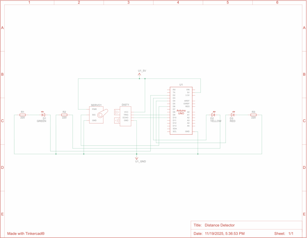
Physical Prototype
Unfortunately, due to the time constraint on this project, I did not make it to actually building the physical prototype.
Below is the circuit diagram.
Reflection
This was a fun project to do and it taught me a lot. I had never built anything with Arduino, but I’ve heard a lot about them. I used to do robotics in my old school for the VEX V5 Robotics Competition and that taught me a lot of the basic skills for robotics, which were helpful for this project and gave me a leg up in the beginning. However, this was much more realistic and complicated. In VEX, I found it much simpler because they had pieces to build the robots and very comprehensive coding. This was a much newer experience and made me learn a lot more.
When I was working on this project, the biggest problem I had was actually building the physical prototype. I originally thought I would have enough time, but when I didn’t, that presented a problem where I realized it would make my grade worse on the project, but I didn’t see anything to do. The other problem was that I wanted to include the whole car so it can back up. This was way too much work, so I simplified it to just including a microservo spinning to certain directions depending on the distance to the object to simulate the wheels of a car spinning.
AI Use & Transcripts
I used ChatGPT when I was building this project. It was useful to help me find a good idea for the project and to teach me how to code with Arduinos, which was new to me.
Our latest project with Fusion was to choose any object and create it with OnShape. OnShape is a CAD software, which means it is meant to be used to create 3D models of things in a computer. This software is useful for 3D printing and industrial manufacturing because you can make one design and then have it be printed or manufactured.
I, the ambitious person I am, decided to make sunglasses. It took me about 5 hours of learning and 10 hours of designing, but it all came together into a questionable looking pair of sunglasses.
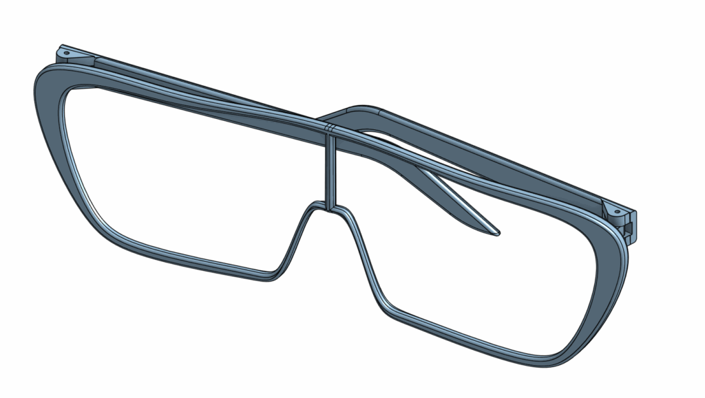
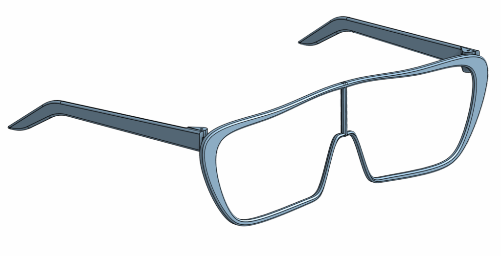
What I Built
I built a pair of sunglasses. The design is inspired by one of my sunglasses at home. I like the wide lenses that cover a lot of your face.
Unfortunately, they do not come with a lens, but they are made as if a lens will go in there. When I built it, I included a slot for the lens to go right into.
How I Made the Sunglasses
It took me 10 hours to build the sunglasses because this is my first time doing CAD. It’s harder than it looks, and I learned that the hard way.
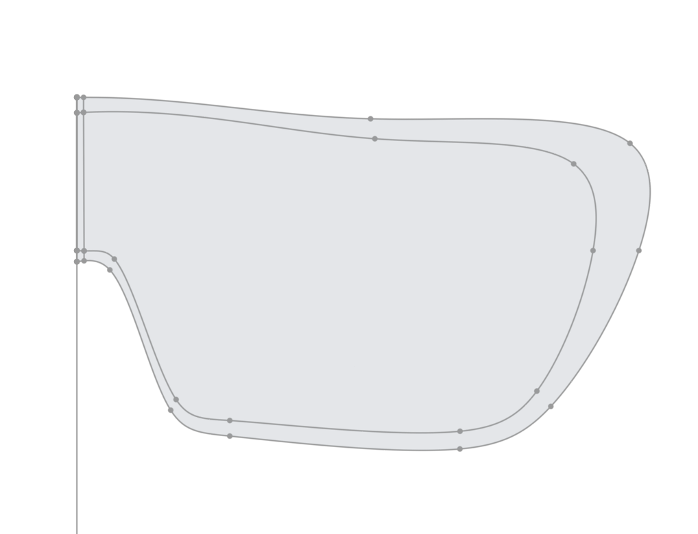
I started by drawing out the shape of the front frame, I left the temple sticks for later as a separate part. I only drew half of it out because I would later mirror it to make the full shape.
After drawing the shape out, I performed something called extrusion.
Extrusion is the premise of OnShape and CAD in general. You begin by drawing a 2D shape, and then you extrude that into a 3D shape.
Next, I work on the holder for the lens. To do this, I cut into the frame just slightly so that there can be a way for the lens to fit right in to the frame. This makes it easier to later work on the lens.
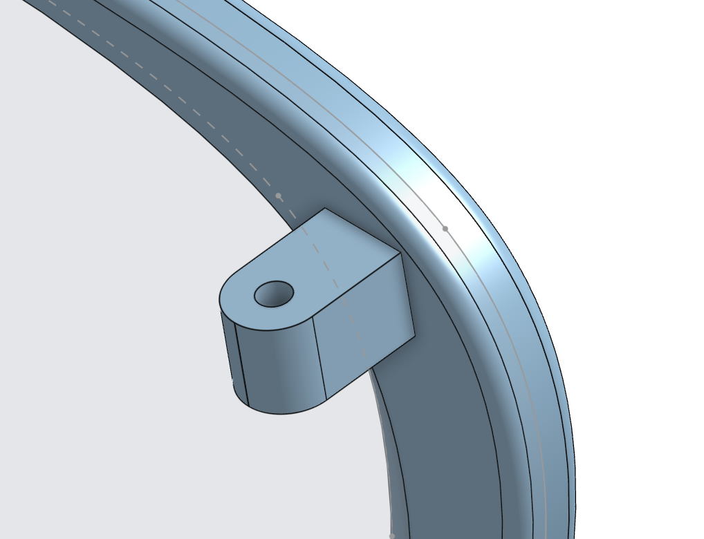
After the main part of the frame is done, I need to make the “door hinge” part to allow the sunglasses to connect to the temples. To do this I create a small part that sticks out of the frame and put a hole into it.
This will allow me to soon attach the temples to the sunglasses frame.
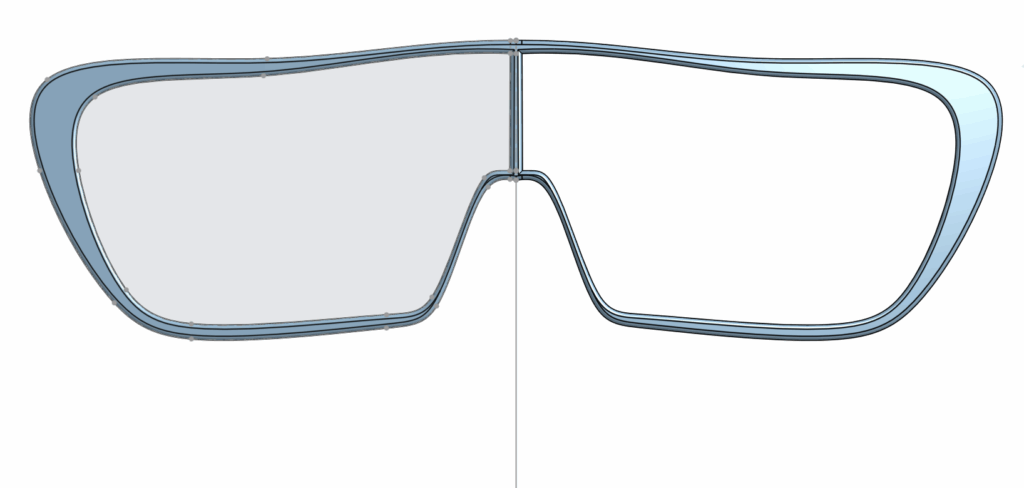
Next I mirror the half over, and I’m done the main frame.
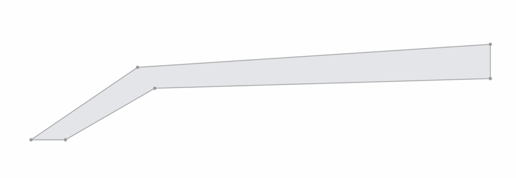
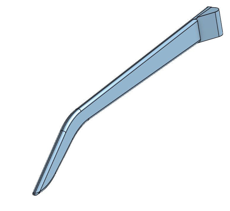
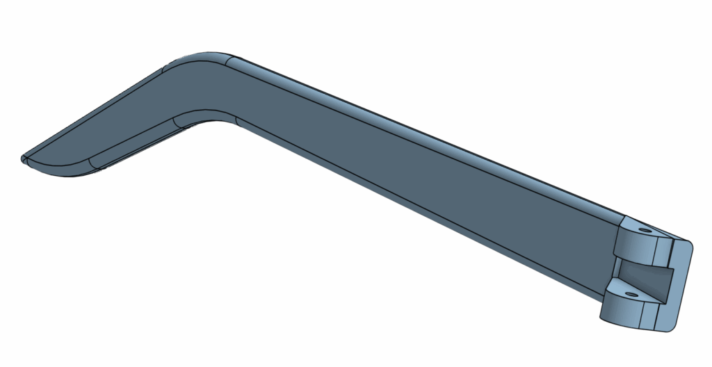
After mirroring it over, I start to work on the temples. I begin, again, with a sketch of the shape of it.
This is a very basic sketch but that’s okay because after this, I can extrude it into a 3D version of this that has a Z-axis. Once that is done I can perform something called a fillet which will give the important detail. It turns sharp angles into smooth curves.
I also add the part that will soon be connecting to the connector part we added earlier to the main frame. The temple is almost done. All I need to do is put the hole down the middle and cut out a section the same size as the connector on the main frame.
Now our temple is done. To get the temple for the other side, I just duplicated this part studio and mirrored it.
The next step is to assemble everything together. To do this, we go to the assembly tab and add all the pieces in. Then, we add mate connectors to connect the temples to the main frame.
And there you have it, a perfect pair of sunglasses.
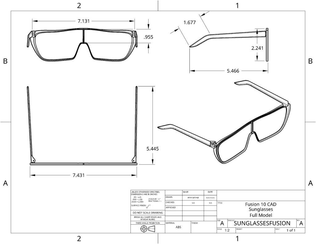
Above is the Mechanical Drawing which shows all the angles of the sunglasses from a 2D “Drawing” style which is useful for manufacturers who can easily understand what they are dealing with just by seeing this drawing.
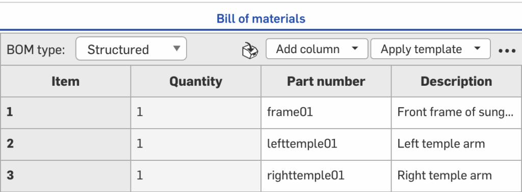
This is my Bill of Materials(BOM) which has all the information about each part of my sunglasses assembly.
Reflection
The biggest thing this project taught me was patience. I kept on trying to go fast and when something wouldn’t work for me, I’d get really annoyed. Slowly as I worked on it, I got better at slowing down, understanding the problem, and building up from there.
When you understand what specifically you are doing, it is so much easier to fix the problem. When you don’t actually know the problem, then it is just really annoying to do.
Even though my sunglasses don’t really look good, I am very proud of them because this was my first time doing CAD, and I was able to take this from idea to 3D model and ready for manufacturing, all by myself.
Our first assignment in the Fusion 10 class was a freestyle coding project. I set out to make a text-based adventure game. It follows a character who enters the dungeon to get a magic item. But in order to get to the item, they must pass through a number of rooms, with challenges sprinkled throughout.
Before I began to code, I started with a flowchart. This is an essential part of any coding project because it outlines the project, giving you a focused way to work individually on each part of the project until the whole of the project is complete.
This flowchart shows the outline of my game idea. Once I had this written out, it made it much quicker to work on the project itself. The coding was very quick and I just went from one part to another.
The Code
Once I had a general plan from my flowchart, I just coded a part, tested it, fixed it, and went to the next part.
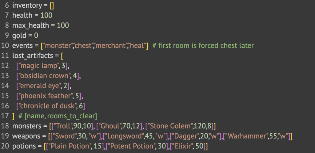
Setting the Stage with Variables
Variables are used to set the state of something. Here, I used the first half of this snippet to set the state of the player.
Inventory starts empty.
Health starts at 100 and max_health makes sure it can’t go any higher.
Gold starts at 0
Events is a list of the room options: a monster encounter, a lucky chest, a valuable merchant, or a benevolent healing room.
The rest after that is lists of items and monsters. Artifacts are used as the item you look for during a quest. The numbers next to them represent how many rooms you need to clear to find the item. After that, it shows the monster or item and the numbers beside them are the stats.
Talking with the Player
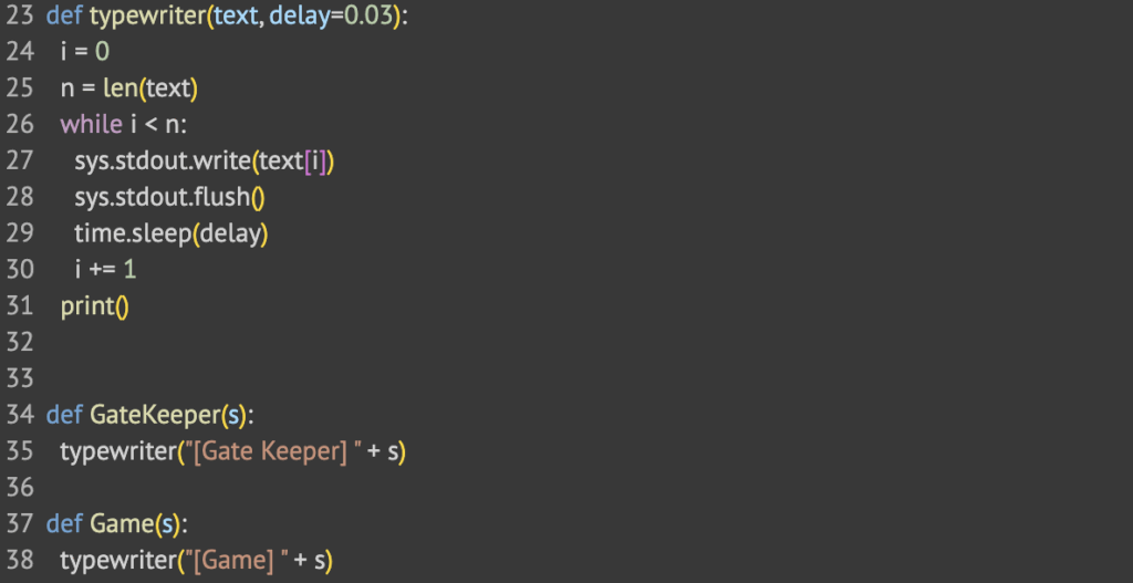
There are three main functions used to communicate with the player.
The typewriter() function gives the game a more interesting way to it by writing the text in a letter by letter way instead of all at once. This makes the game more immersive.
The GateKeeper() function is used to keep communication from the gatekeeper consistent.
The Game() function is used to keep communication about the game consistent. This is mainly description.
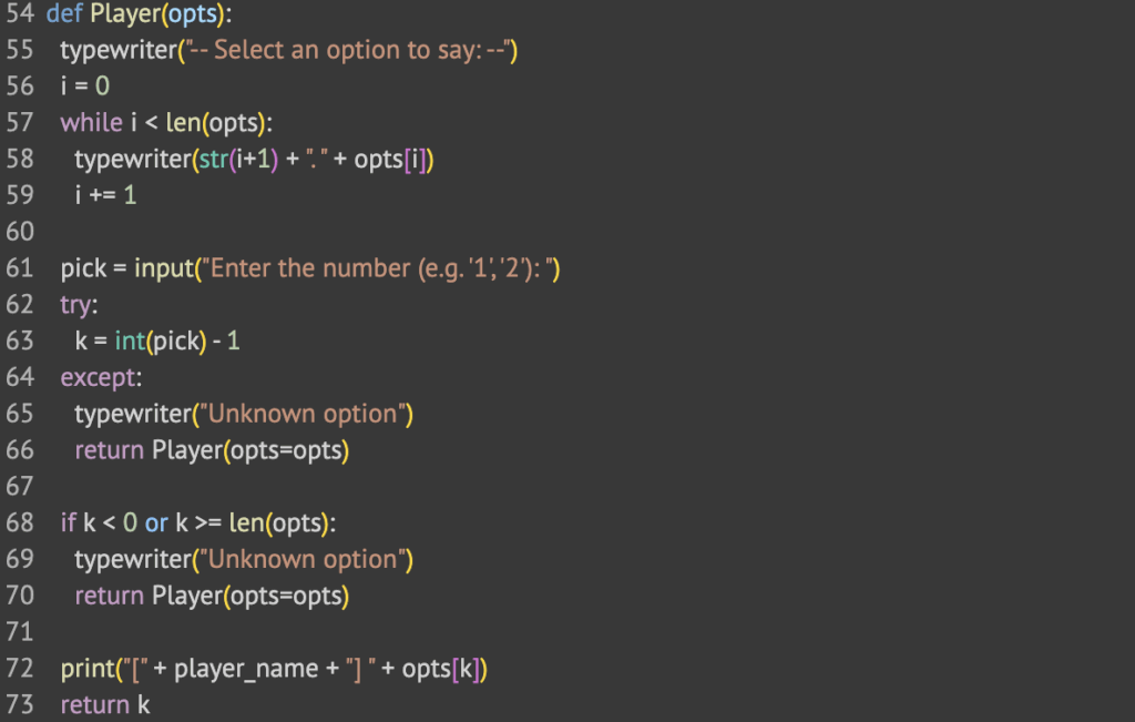
The player function is important. This is how to receive input from the player to make the game more interactive. It works by receiving an input of a list of options and then the player chooses which option they would like to say.
Logic Behind the Dungeon Rooms
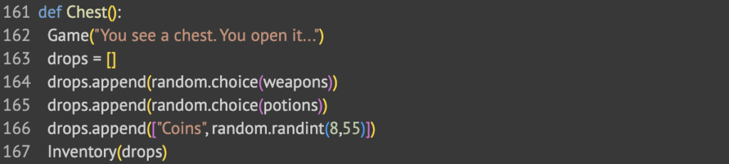
For the Chest() room, I wanted it to always give a weapon, a potion and a number of coins. To determine the weapon and potion, it chooses a random one out of the list that we defined earlier as a variable.
The HealRoom() brings you closer to max health. After a fight with a monster, this is one way to heal your health to prepare for another fight. It works by saving the old health in a variable, then adding the heals to the old health. If that is more than max_health, then it sets health to max_health, otherwise, it just leaves it.
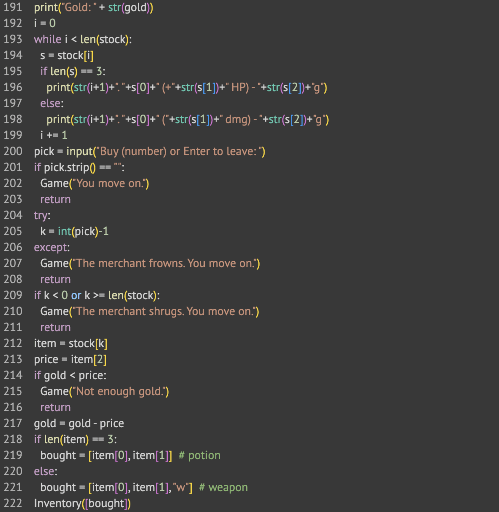
The Merchant() room is a way for players to buy equipment to keep them better prepared for future fights with monsters. First I define a list of items that you can buy from the merchant. Then, it runs through a loop. It asks what item you would like to buy, then makes sure you have the gold to buy that item. If you do, then it gives it to you and takes away the gold.
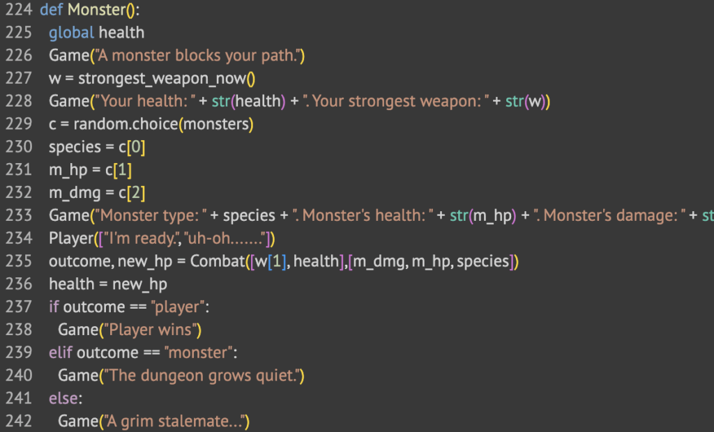
The last and most complicated room is the Monster() encounter room. It first types out the stats of both you and the monster then it does the combat in the combat function, which I will get to later. It then goes on to print if the player won, if the monster won, or if it was a stalemate.
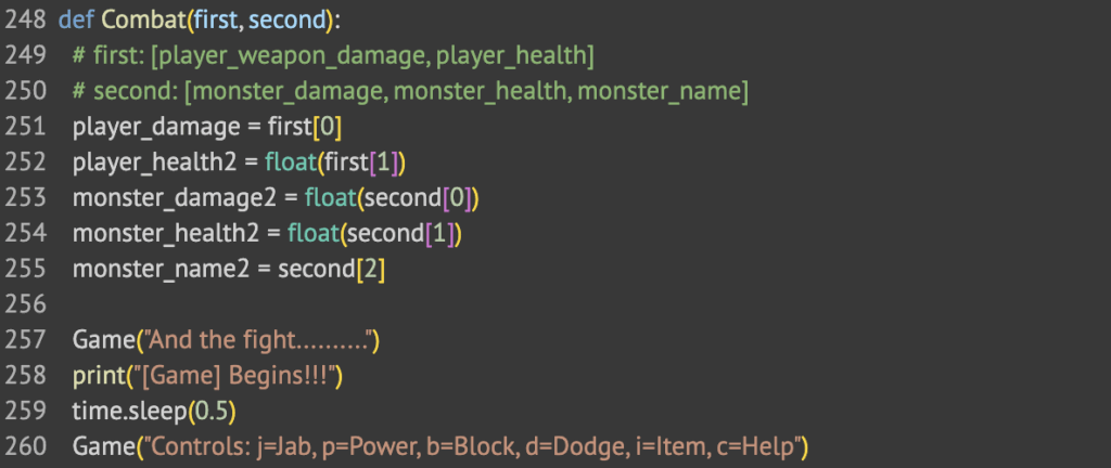
The Combat Function
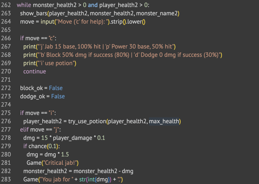
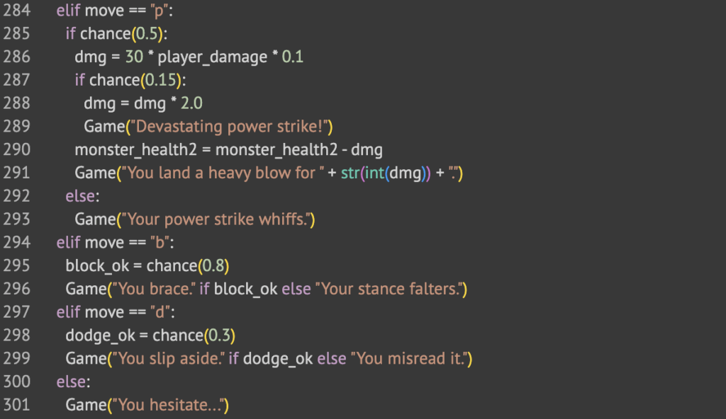
The Combat() function starts by getting the stats of both the player and the monster. Then, it lists out the controls that the player can use. I made combat a turn by turn based fight. The player has the option of all these controls. After the player inputs a move, the monster makes a move and there is a small chance it does a lot of damage.
The code above is how the game understands what key is pressed.
When “c” is pressed, it shows a list of controls
When “i” is pressed, it uses a potion on the player to heal
When “j” is pressed, it does a simple jab. There is a 10% chance of a critical hit.
When “p” is pressed, it does a power strike. There is a 15% chance of a critical hit.
When “b” is pressed, it does a block, which negates some damage from the monster.
When “d” is pressed, there is a small chance that you will completely dodge the attack from the monster.
If you choose the wrong control, it means you hesitate and the monster still hits you.
The Prize Room
When you complete the specified amount of rooms for your artifact, you are taken to the prize room. It adds it to your inventory and then teleports you back to the Dungeon Master.
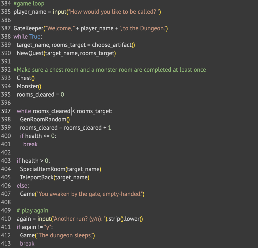
Game Loop
The game starts by asking the player for their username. Then they are greeted by the Gate Keeper and given their first quest. The game always makes the player go through a chest room then a monster room before starting the random room loop. Then once they go through enough rooms, they are taken to the Prize Room. Finally, they are asked to play again.
Reflection
This project was a fun thing to do. I learned how to use libraries I never really used before that much and it made the game so much more interesting. I made sure not to use AI because I like to use ChatGPT to do all the monotonous parts but I forced myself to write all the text myself, and it made the game that much better to make. It is a simple game but it still was fun to make.
The main thing I learned from this project was the importance of planning before coding. I never really used flowcharts on any of my coding projects but using it genuinely made my job so much easier. I just went from part to part and it was so much faster. I moved so quickly.
It was fun at the end to see how I had made a game where no two games are exactly the same all because of random chance. This is a very simple concept but I never really have used it like this.