Vincent Zhao 2/10/2025
Abstract
One last time, we look back at the initial problem statement.
We set out to design a human operable vehicle, capable of traversing a 10 kilometer round trip through titan.
The hover drone prototype is designed to test the feasibility of aerial mobility relevant to Titan-like conditions. Specifically, this prototype shall be used to evaluate a drone’s efficient lift-off, sustaining controlled flight, and making a 10 km round trip, bound to constraints similar to the low gravity and dense atmosphere of Titan. It shall also assess stability in simulated wind conditions and energy efficiency for longer distance travel.
This test was designed to evaluate the energy efficiency of our prototype drone during two types of flight paths: a straight-line path and a path with multiple turns simulating navigation over Titan’s rugged and mountainy terrain. These tests aim to provide insights into how our full-scale vehicle might perform under similar conditions. For more details on the design and concept, refer to the planning post.
Final solution
Our testing process was significantly compromised due to physical errors in building our drone. Initially, we had a well-structured plan: we would individually purchase drone parts, 3D print the frame of a CAD-designed FPV drone, and solder/glue the everything to the frame. However, before winter break, we realized that the printed frame was too small and incompatible with our motor parts. Additionally, our limited experience with soldering and circuitry made the assembly process far more difficult than anticipated.
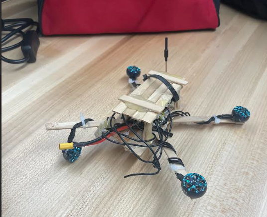
To address this, our building leader, Joe, took the drone home over the break to work on it. Unfortunately, one of the circuits got fried during the process, leading him to reconstruct the frame using hot-glued popsicle sticks as a last-minute solution. Despite our best efforts, upon returning from break, we continued to face technical difficulties. The motors never fully calibrated, causing severe imbalance, and the drone was ultimately unable to achieve stable flight. After numerous failed attempts, we made the difficult decision to scrap our original drone and instead conduct tests using a fellow robotics teacher’s working drone with a similar weight. The measuring was made even easier as he had DJI drone goggles, which allowed us to actively see the voltage per cell in the display.


Procedure
Materials
- Small drone (250 g).
- DJI goggles
- Pre-measured field (100 m).
- Drone controller.
Preparation
- Drone Setup:
- After getting these materials, we read the initial voltage and record the value
- Mark Testing Area:
- We decided to fly the drone length-wise across the main senior school field, which is around 100m.
Test 1: Straight Flight Path
- Use the drone controller to fly the drone in a straight line along the path and back
- Maintain a steady height and as straight a flight as possible.
- Land the drone at the endpoint and measure the remaining battery voltage.
- Initial voltage, and final voltage.
Test 2: Maneuverable Flight Path
- Guide the drone along a random maneuverable flight path, with multiple zig zags and turns with two AA batteries strapped onto the top to simulate realistic conditions
- Land the drone at the endpoint and measure the remaining battery voltage.
Data Collection
For our data collection, we focused on measuring voltage per cell (V/PC) for battery use. We conducted two types of tests:
- NL (No Load) Straight Flight: The drone was flown in a straight line without additional weight, simulating a simple, controlled flight.
- L Zag (Loaded Zigzag) Flight: To better simulate real conditions on Titan, we taped on two extra 31g batteries to simulate the weight of a human passenger and flew the drone in a zigzag pattern to try and replicate the need to navigate around potential obstacles in Titan’s unknown and mountain filled terrain.
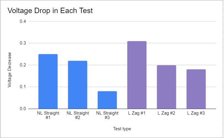
The following table presents the recorded voltage per cell at the start and end of each test, along with the overall voltage drop:
| Test type | V/PC at start | V/PC at end | Voltage Decrease |
| NL Straight | 4.16 | 3.91 | 0.25 |
| NL Straight | 4.08 | 3.86 | 0.22 |
| NL Straight | 3.78 | 3.7 | 0.08 |
| L Zag | 3.91 | 3.6 | 0.31 |
| L Zag | 3.65 | 3.45 | 0.2 |
| L Zag | 3.55 | 3.37 | 0.18 |
The test itself preformed as we intended it to. Although we changed up the procedure during the day of the test due to unexpected setbacks and using an external prototype, there was still an ample amount of data gathered for evaluation. The only issue is that there was not enough proper coordination for us to have specific control variables. For example we only had a No load straight and Load zigzag tests, when we could have included no load zigzag and load straight. However, we were on time constraints and the two tests we conducted are enough to simulate a control variable, and a realistic flight conditions variable as we flew the drone there and back three times for each test.
Data Analysis
For the six individual tests we flew, we recorded the starting and final values before and after the round trip. Our data shows that the battery voltage drop per cell (V/PC) decreases slightly from one test to the next. This trend might be due to the fact that in each test the drone begins its flight from a resting position on the field. Because the drone is initially landed, the energy consumed to lift off.

Defining Efficiency
In our tests, we define the energy efficiency of the drone in terms of the battery’s voltage drop per cell per meter flown. We assumed that the voltage drop (ΔV) is a direct indicator of the energy consumed by the drone during the test. Therefore, efficiency is expressed as:
Where ΔV is the Voltage Per Cell (volts), and D is the total flight distance in meters
This allows us to measure volts per meter. A lower value indicates more effieicncy
Calculating Voltage drop
We conducted two sets of tests:
- No Load (NL) Straight Flight:
The voltage per cell (V/PC) was measured before and after flying a 110 m straight-line course.
The recorded voltage drops were:- Test 1: 4.16 V−3.91 V=0.25
- Test 2: 4.08 V−3.86 V=0.22
- Test 3: 3.78 V−3.70 V=0.08
The average voltage drop for the NL straight flight tests come out to be 0.1833 V
- Loaded Zigzag (L Zag) Flight:
Here, the drone flew a maneuverable zigzag path with additional weight (two extra 31 g batteries) to simulate a human passenger. The recorded voltage drops were:- Test 1: 3.91 V−3.60 V=0.31
- Test 2: 3.65 V−3.45 V=0.20
- Test 3: 3.55 V−3.37 V=0.18
The average voltage drop for theses is 0.23 V
How we got efficiency
Given that the total flight distance for each test was 110 m (length of our rugby field), we calculate the efficiency for each test type:
NL STRAIGHT:
L ZIGZAG:
The higher voltage drop per meter in the L Zag test shows that maneuvering through turns and obstacles increases energy consumption.
Scaling the conditions to Titan’s Conditions
Titan’s environmental conditions – a gravity of approximately 1/7 of Earth’s and an atmosphere that is about 50% (or 1.5 times) denser – affect energy consumption for flight. These factors improve lift efficiency and reduce energy requirements.
Together, these factors reduce the energy required for lift. We combine these effects with a reduction factor that can most likely be:
From here, adjust for the full scale efficiency values to simulate Titan’s conditions:
While there isn’t a standard “volts per meter” benchmark for full-scale vehicles, our scaled values indicate that under Titan’s conditions, the energy required per meter would be significantly lower than on Earth. The improvements by a factor of approximately 10.5 imply that our design is solid for a Titan environment.
Summary
Our testing and data analysis highligted that our drone’s energy efficiency, in V/PC per meter, differs between a straight line, and a maneuverable zigzag flight. In our NL straight flight test, the drone experienced an average voltage drop of approximately 0.1833 V over a 110-meter flight for an efficiency of 0.001667 V/m. In contrast, the loaded zigzag (L Zag) test – where we added extra batteries to – yielded an average voltage drop of roughly 0.23 V and efficiency of 0.002091 V/m. These values show that a more realistic path, uses around 25% more energy per meter compared to a straightforward flight. Furthermore, our design basically rested upon the air density and lower gravity considerations, which allow for less energy use by what we assume would be 10.5x.
Our initial design was too complex. We tried to use an overly advanced CAD frame that was ultimately incompatible with our motor parts due to size, and, at the time, we all lacked experience with soldering and circuitry. We did gain experience in these skills; however, focusing on functionality will likely result in a more successful prototype next time.
Another issue was our lack of communication and coordination. Our main builder, Joe, had to work on the drone independently over winter break, and was unfortunately forced to replace the frame due to wiring issues. Personally, while I regularly chcked in and helped with soldering, much of the critical work fell to one team member. I believe that if we established goals and all collaborated in design, it would help avoid wasted time. Although our initial plan was quite solid, the end result was us having to use a fellow robotics teacher’s working drone rather than our own prototype. Although his drone allowed for an easier way to measure the data we needed for our tests, it would have been the best to see our own creation succeed.
Overall, this process of designing and ideating for our own vehicles was quite fun, and we learnt many things about the process of a design cycle that can help improve for if another similar experiment happens. Even though we faced challenges, a 5 kilometer round trip on Titan has been simulated to be possible and efficient with our proposed design.
Leave a Reply