Before I dive into explaining how I made the robotic arm, I would like to note that this is a fusion of both my arduino project and my CAD project. I will start with explaining the arduino portion, then further down I will explain the CAD portion of this creation.
Physical arduino portion:
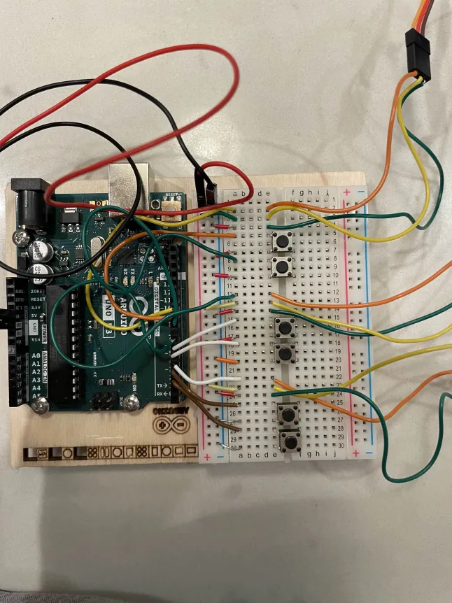
This is a photo of the physical arduino. I have connected the servo motors to a positive, a negative and a pin. I have also connected the buttons to a negative and a pin. The pins are located in a black line on the green part of the arduino. They are the closest thing to the breadboard which is the white panel that many of the worse are. The pins have many wires feeding into them and they are very useful for identifying different parts that the code can turn on and off.
Arduino coding portion:
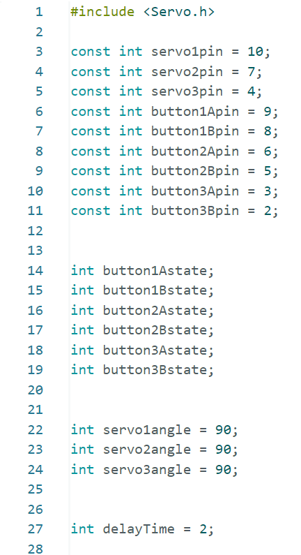
At the start, I had to import a function in order for the code to recognize what a servo was by giving it a digital library of information. This is useful because I am unable to run any commands revolving around servos without this.
The next thing I did was label the different physical components of my arduino by labelling the pins that they are assigned to.
by turning the button states into integer values, I am allowing them to be turned off and on because in binary 0 is false (or off) and 1 is true (or on).
The next thing I did was define a variable called a servo angle. I set it to 90 so that at the start of my code, all servo motors will be 90 degrees. This is useful because it allow me to turn the motors by changing the angles of them using code.
After, I added a small delay to ensure that my servos do not get sent too much information too quickly. This could overload them and ruin my code. This is called a rate-limiting variable and it is used to make sure users do not exhaust the system’s resources.
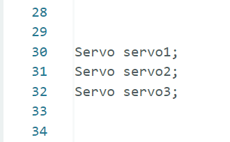
In these lines I made the arduino recognize 3 names labelled servo1, servo2 and servo3 become recognized as an actual servo motor object. I could not have done this without my first step where I imported a servo library.

I then moved onwards to the setup. Here I made all of the button modes “INPUT_PULLUP” pins. This means that the arduino will automatically set their charge to “HIGH” unless they are pressed. In the scenario that they are pressed, they will be set to “LOW”.
The next thing I did here was connect the actual objects with the digital pins in order to identify them.
Line 48 intializes a connection between my computer and my arduino board where 9600 is the communication speed in bits per second.
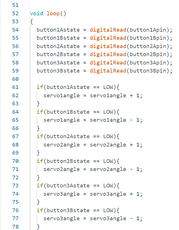
This is the start of my loop. A loop is a function that is repeated constantly when the code starts running.
The first thing the code does is check whether or not the buttons are “HIGH” or “LOW”. Then below it shows that if these buttons are “LOW”, meaning they have been pressed, they will turn the angle of the servo motor clockwise or counterclockwise depending on if they are negative or positive.

In the last portion of my text, I made the servos turn from 0 to up to 180 degrees. After this I used a command that writes the code. What this does is it allows all the code I have typed to actually be ran instead of not being put into use. The print command below it sends the data that the write has ran to the robot.
The delay I added at the end was to make sure that the code does not get jumbled up and goes at a much more manageable pace.
Here is a link to the code on a google doc: https://docs.google.com/document/d/13TFJx3z5BNAGUjONt2EyzvM6vkltd9bUTq3OYGtUTqM/edit?usp=sharing
Here is a link to a video of the robotic arm: https://drive.google.com/file/d/1K8Mzg9UtFN4uV68t8XpDTyb663r1qonR/view?usp=sharing
CAD Portion:
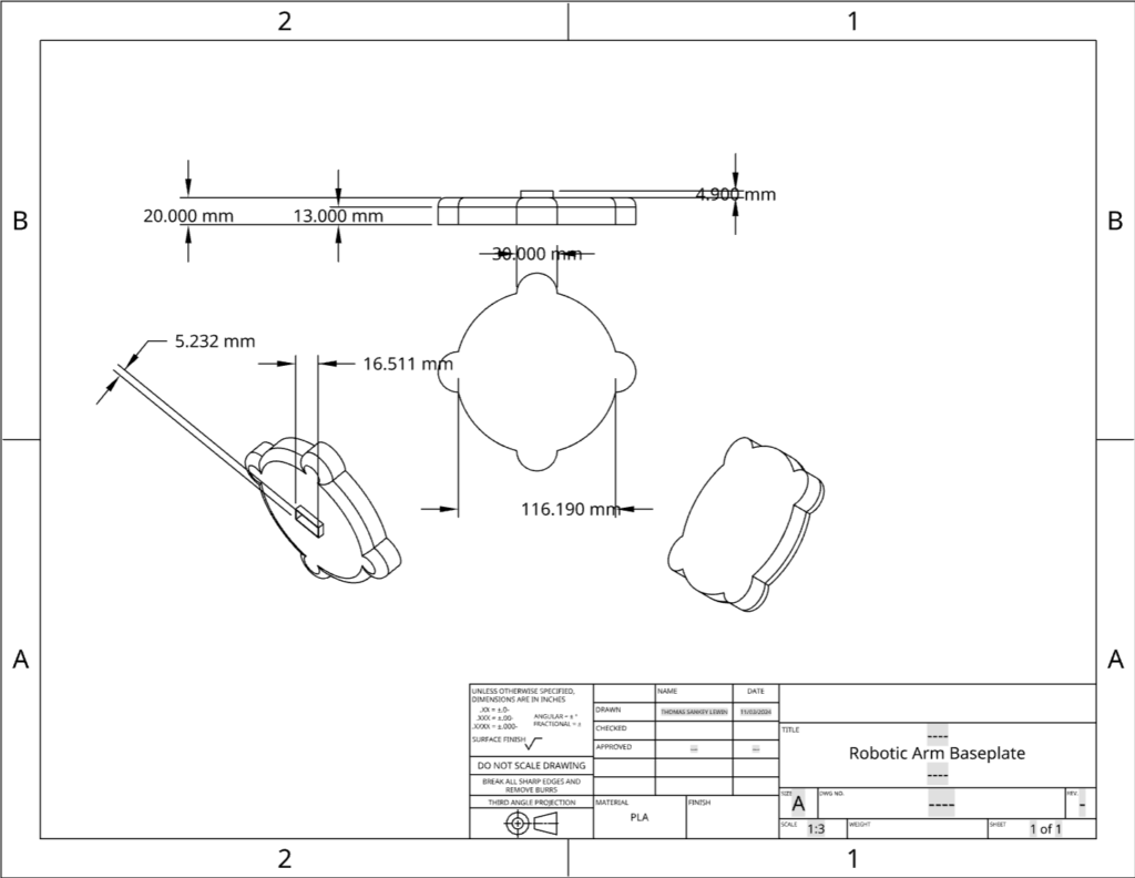
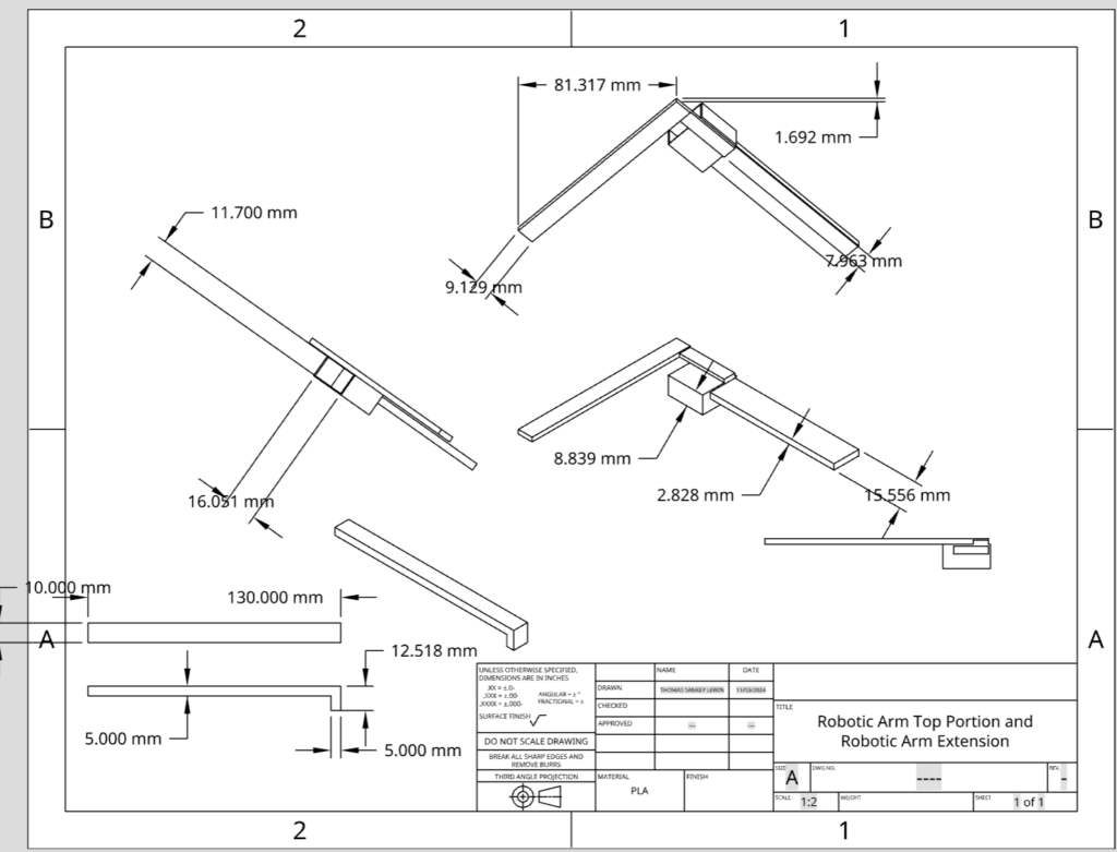
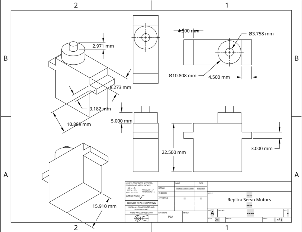
For the CAD portion of this project, I will display both the 3D CAD portion of the project and a 2D blueprint portion under it.
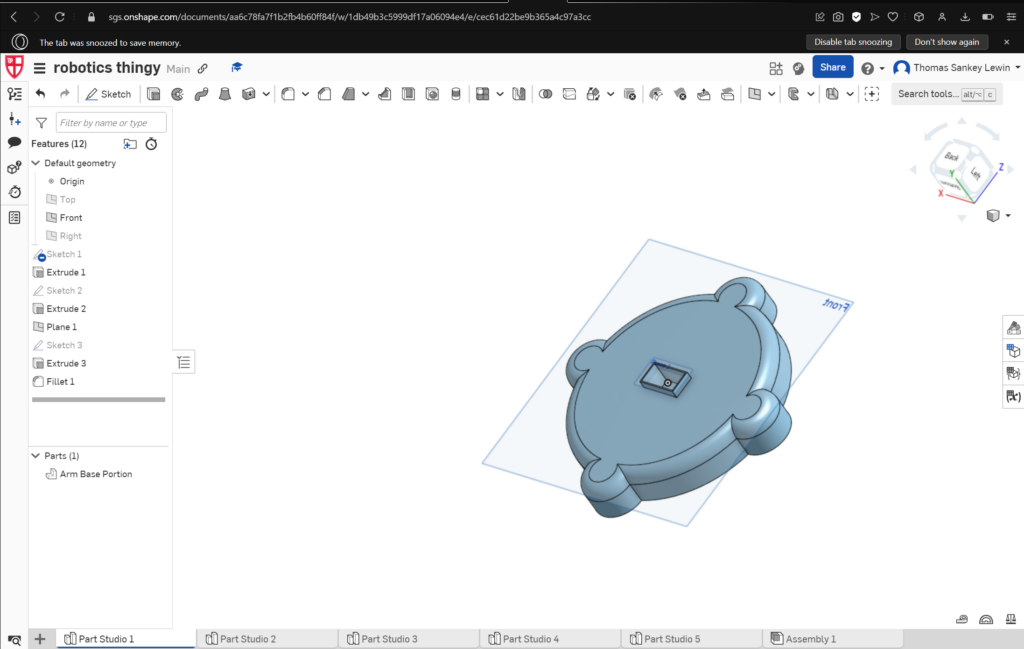
After finishing the code and getting the arduino to work, I moved onto the CAD portion. I started with a base in order to support my arduino and make sure it does not fall down. Building my base, I learned how to create a sketch by tapping the sketch icon and selecting which plane I want. Then I figured out how to use the extrude tool where I would go to a square that I have created using a sketch and extrude it by a certain about of centimeters, adding depth to it.
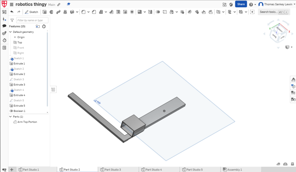
After that I moved onto the top part. Within the top part I learned about using construction lines for reference, which are lines that I can draw onto a shape without the shape being changed. I used these construction lines to create dimensions where I would measure the distance of two points and change them to increase and decrease the size of shapes. I also furthered my understanding of extrusions by creating negative extrusions that creates a hole in the shape so I can fit a motor in it. After learning this, I went back to my base plate and added a slot for my motor.
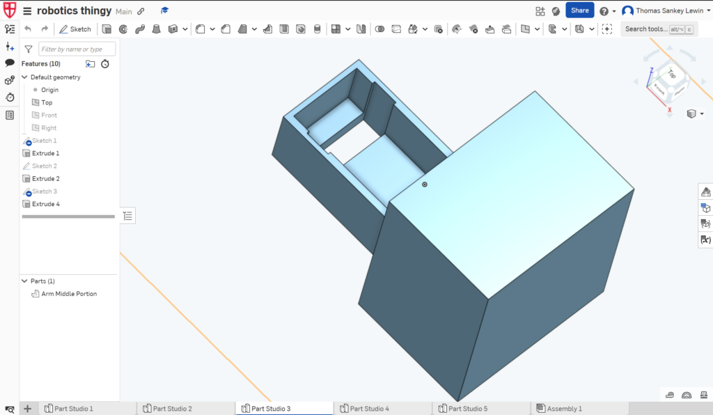
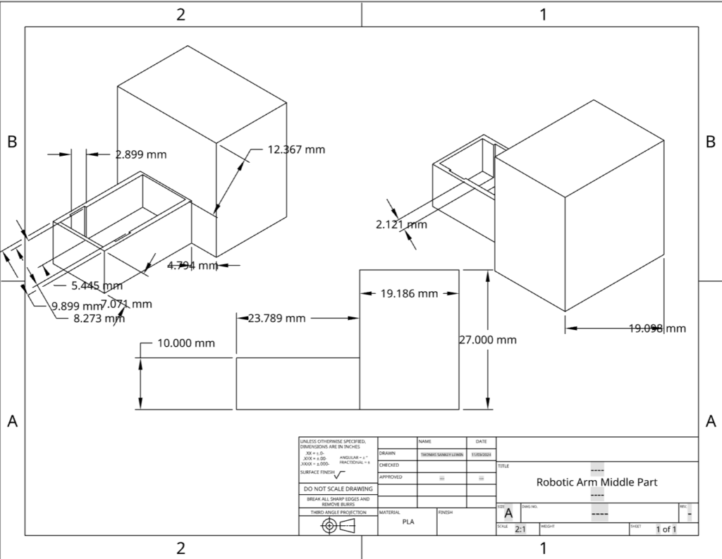
I then created the middle part of my build. I needed to create this after my top part because I needed to relatively guage how big the box on the back of the middle part needed to be. I needed this box sticking out of the back in order to balance out the weight of the arm to make sure that the weight is distributed so it doesn’t tip over.
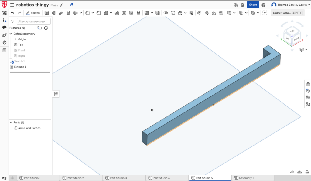
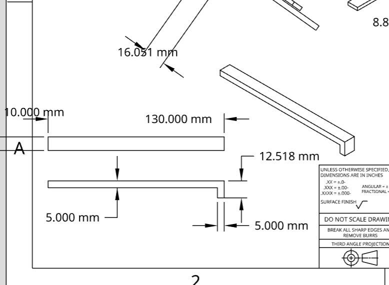
I then quickly constructed an arm part that will become the claw when I go to assemble this build.
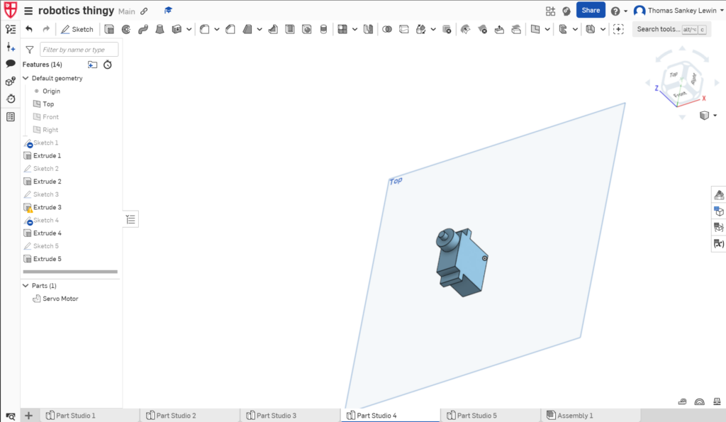
I also made a 3D sketch of a servo motor in order to be able to combine all of my pieces in the “assembly” portion of my design which is shown down below.
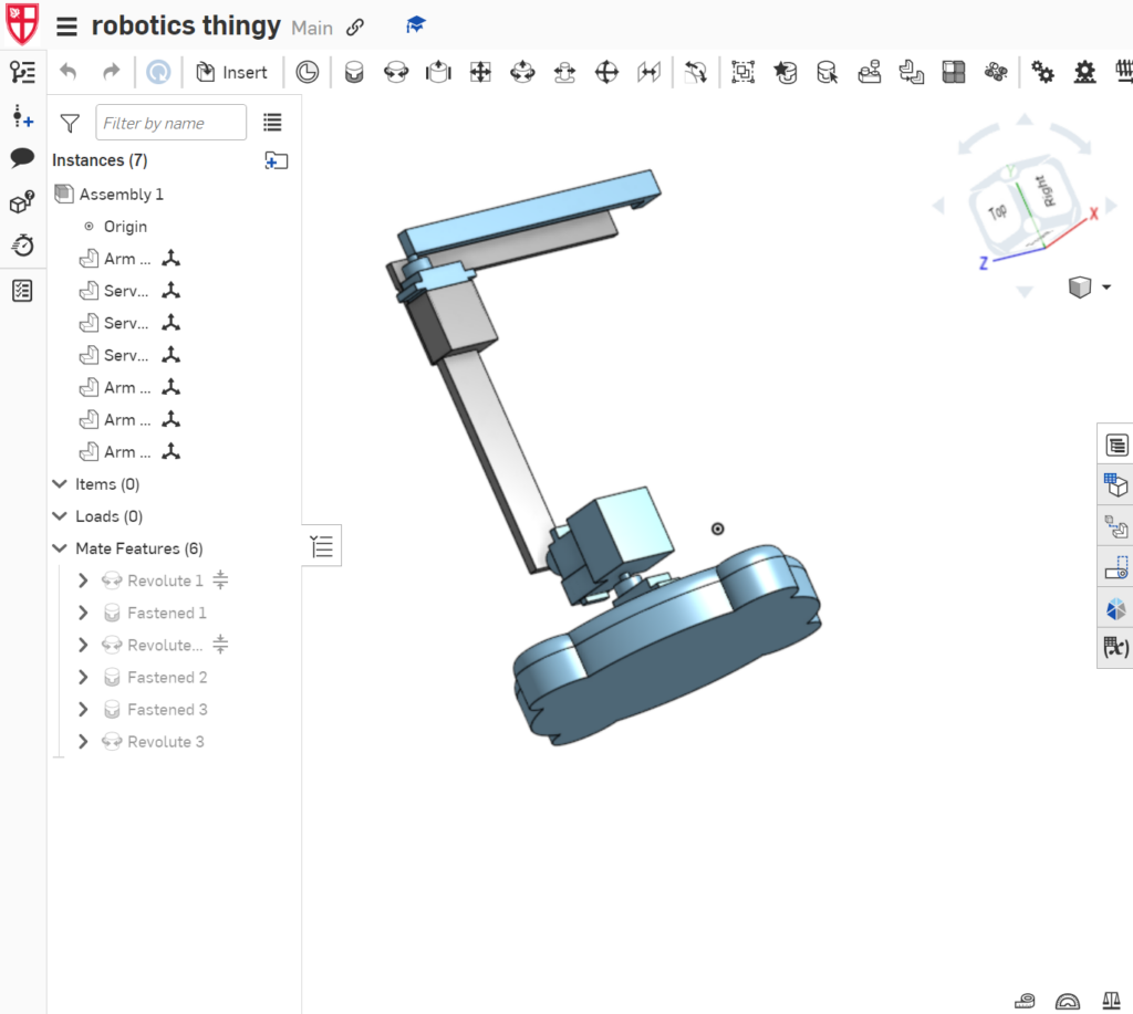
As stated, this is the final model of the CAD design. It includes all of the pieces which have been “mated” together. A mate is a tool used for putting 2 pieces of a build together. Mates are really helpful because they can demonstrate how an object will rotate when moved. As shown on the bottom left, I used fastened mates and revolute mates.
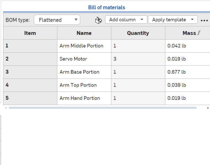
Along with creating the actual 3D models, I have also created a “Bill Of Materials”. A bill of materials shows different things depending on how you edit it, but I decided to show the name of the item, the number, the amount of items I am using in my build, and the mass of each item. I needed to include the mass of each item in order to see how much the box in the “Arm Middle Portion” needed to be.
Leave a Reply