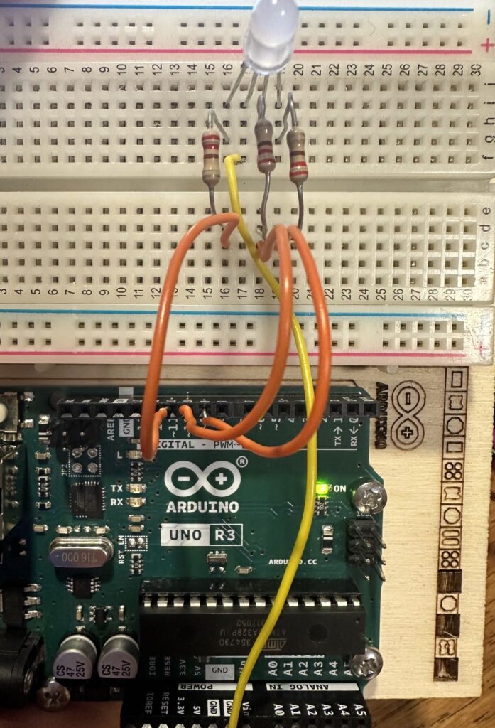
For the robotics assignment, I chose to create a RGB light color mixer that cold blink the requested amount of times as inputted by the user on the serial monitor. I finished the project in the following order of steps: code, simulation, and final project.
CODE
I wrote the code with four parts, the first being the creation of the color mixing function, the second being the setup of the code, the third being the gathering of user input, and the fourth for the execution of the user input.
void setColor(int R, int G, int B) {
  analogWrite(11, R);
  analogWrite(9, G);
  analogWrite(10, B);
}
I named the function for setting the color for my RGB light setColor, which functions by giving the three pins on the led (R, G, B) the correspondent values inside the parenthesis which ranges from 0 – 255.
void setup(){
  pinMode(9,OUTPUT);
  pinMode(10,OUTPUT);
  pinMode(11,OUTPUT);
  Serial.begin(9600);

}
Then, I used the void setup function to setup my pins by designating the three pins for the three colors that will be mixed together.
void loop(){
  Serial.println("red value (0-255): ");
  while (Serial.available() == 0){
  }
  int R = Serial.parseInt();
  Serial.println(R);
  Serial.println("green value (0-255): ");
  while (Serial.available() == 0){
  }
  int G = Serial.parseInt();
  Serial.println(G);
  Serial.println("blue value (0-255): ");
  while (Serial.available() == 0){
  }
  int B = Serial.parseInt();
  Serial.println(B);
  Serial.println("how many times do you want the circuit to flash?");
  while (Serial.available() == 0){
  }
  int y = Serial.parseInt();
I also gathered user input about the intensity of each component of the color of the RGB LED and also the amount of times that the user wants the LED to blink. I also used the Serial.available function to create an infinite loop if there is an absence of user input, which gives the suer enough time to input a value.
int x = 1;
  for (x=1 ; x<y+1 ; x++){
    setColor(R,G,B);
    delay(1000);
    digitalWrite(9,LOW);
    digitalWrite(10,LOW);
    digitalWrite(11,LOW);
    delay(1000);
  }
  delay(1000);
}
For the last part, the code is executed as the for loop makes the lights go on and and off repeatedly and stops when the blinking code completes the indicated amount of times. I used the setColor function that I created at the start of the program to set the color for the LED as it flashes.
SIMULATION
To simulate the project, I constructed the circuitry into tinkercad and inputted the code. This is the code to the simulation: https://www.tinkercad.com/things/7wJlrRRnIiV-fusion-robotics?sharecode=_DMjHrDAL3ooAF9OWBsVLSXIIJuPrRbyrf2AahggBDA
The simulation is mostly accurate, but the system miscalculates the current passing through the LED which causes incorrect warnings of possible overheat of the LED that would not have happened in real life.
FINAL PRODUCT
After the simulation of the project, I put together the pieces and constructed the final product of this project.

– The looks of the final product
I also ran the code with the actual model, and the results were ideal. This is the link for the demonstration of the project: https://youtu.be/o-rBb9Atbe8
This is a generally successful project, as I discovered more about the serial functions of the Arduino coding software, applicable to further projects that require user input. Another important function that I learned through this process is the void function, as it allows for the creation of custom functions, which also means a more concise and simple code. The principals applied for this project could be expanded to further projects exploring user input, custom commands and functions, and RGB lighting.
Leave a Reply