During the last term of the 2024 – 2025 school year, I created a simulation project on the effects of adjusting the positioning of the intake of an internal combustion engine in both racing and road cars.
Pt.1: The Problem & Theorization
The problem that has existed since the start of the aerodynamics era of racing is that there always isn’t enough grip in the corners. The reason for this is that there needs to be less drag in the straights to achieve higher speeds and that more grip in the corners means slower speed in the straights. Thus, cornering speed is often sacrificed in order to achieve an overall better lap time and faster straight line speed. Active aero is an approach to this problem, where aerodynamic components adjust their position in order to increase or decrease grip and actively adjust the aerodynamic qualities of the car for corners or straights. Straight line speed is one of the most important components of a good racing car, as a faster car in the straights would mean faster lap times and also more overtaking opportunities. In addition, faster straight line speed would also mean that cornering speed could also be increased as a faster car in the straight means that there can be more grip allocated to the car without decreasing overall lap time.
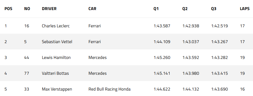
– The qualifying results of the F1 2019 Spa Francorchamps Belgian GP
The dominant engine power in the Ferrari F1 car made it fast in circuits like Spa Francorchamps that require fast straight line speed. The allegedly illegal Ferrari engine qualified 0.7 seconds ahead of the Mercedes cars, showing the advantage that cars can have from faster straight line speed.
Many F1 teams have done work to either decrease the drag of a car in the straights or increase the downforce of the car in the corners. The most famous examples are the F duct designs and the ground effect suction cars for the two approaches listed above respectively.
Pt.1.1: The F Duct
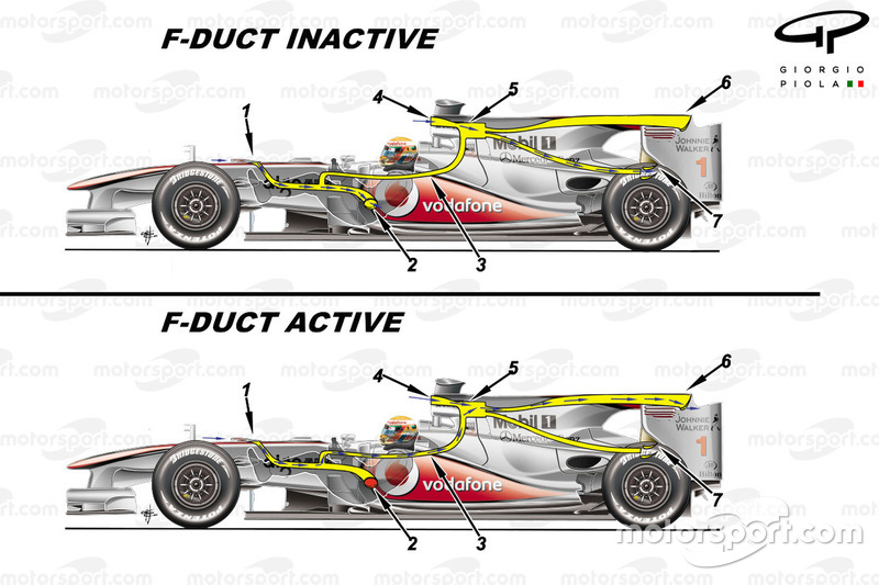
– A diagram of the F-Duct system invented by the McLaren F1 team
When activated, the system uses the air from the front of the car and guides it towards the back of the car to decrease drag. This seemingly insignificant design gave McLaren an advantage over competitors, and the design was soon copied by many other manufacturers in F1.
Pt.1.2: Fan Cars
Another great invention in F1 history was the Brabham fan car, which uses a fan system to decrease pressure in the underbody of the car and thus suck the car to the ground while also increasing cooling effects.
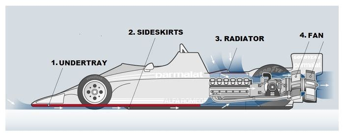
– An image showing the inner workings of the Brabham BT46b f1 car.
This design relied on a fan that is connected to the engine to suck air out of a sealed underbody. To put in simple words, the engine provided power to a fan that sucked the car to the ground.
However, despite being ruled legal by the governing body of Formula one, the car still faced withdrawal from the competition due to unspecified concerns from the owner of the team.
Pt.1.3: How I Came Up With My Solution
When I saw what the BT46B could do in the 1978 F1 season, I wondered if some of the same principals could be translatable to current F1 car designs.
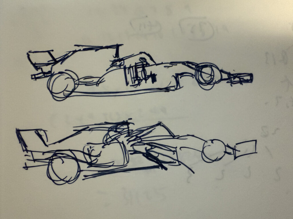
– One of the first sketches that I made regarding this idea
One of the key tendencies that I saw for cars in general is that the positioning of the intake is almost never largely adjusted or changed to provide an aerodynamic advantage. In general, the intake is always located at the top or front of a car. I thought that since engine intakes are a source of suction, why can’t they be utilized to provide a performance gain? I theorized that by positioning the intake towards the bottom of the car, the intake will preform a similar function to the BT46B F1 car, where a partial vacuum would be created and there will be an increase in downforce. Then, I moved on to actually modeling the system through CAD and CFD simulations.
Pt.2: Modeling
To keep up with recent F1 regulations, I chose to base my model off of the 2022 regulations era, which is the most recent era of regulations regarding the floor structure of F1 cars.
I looked at models of F1 cars, and chose to purchase a model of a F1 car to save time for modeling. I chose the most recent F1 CAD model that I can find, being a CAD model of a 2023 regulation F1 car.
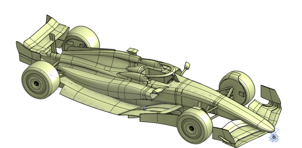
– An image of the CAD model I purchased off the internet
However, the model was unusable as it was a surface model where the body is not solid. This aspect of the model made it incompatible with the CFD software I was using, SimScale. As a result, I had to make a model on my own. As I was only concerned with the performance of the altered floor structure, I only needed to replicate the floor.
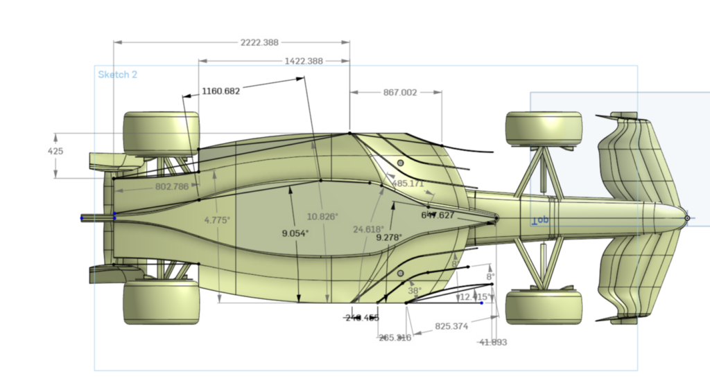
– An image of the measurements I took
I took the measurements from the original CAD model and used the data to construct my own CAD model of the 2023 regulation floor structure. This also made it easier for adjustments to be made to the floor structure. I also added my modifications and sent the model to the CFD software.
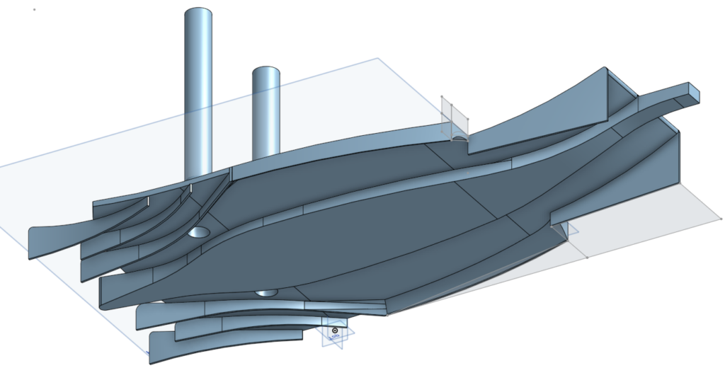
– An image of the first CAD model I made for the final CFD tests
Pt.3: Turning Point & Difficulties
However, after the CFD results came out, the data turned out to be the completely opposite of what I expected. What instead happened was that there was a decrease in both drag and downforce.
However, on the positive side, this would mean that the system will have big benefits for the car in terms of straight line speed and performance.
The altered floor, in comparison to the original floor, produced 200 N less drag and only had around 24% of the original downforce.
Despite the fact that the overall data seems to be legitimate, as the trend of decreased downforce and drag seems to be the same for some other tests of other floor structures I did, the downforce decrease seemed too dramatic, and is a phenomenon that I haven’t yet been able to completely decipher yet.
A possible cause is that I made an assumption on engine suction that could be inaccurate. I calculated the displacement by multiplying the RPM of a F1 engine by the 1.6 L displacement of the engine, producing a theoretical result for the amount of displaced air that could be largely inaccurate.
This problem is also largely unresolved, as there aren’t any accessible data for the displacement of a F1 engine. As a result, any meaningful results for a Formula one car will have to be from wind tunnel experimentation on a modified F1 car or with actual data from a F1 team.
Thus, I changed direction yet again to see if there are other possible benefits from positioning the intake of a car at the bottom of the car.
Pt.4: Ram Air
I realized when I was doing the simulations that as the floor of the car is a venturi tunnel, one of the key features of the floor of a F1 car is that fluids flow faster at the bottom of the car then at the top of the car in accordance to the continuity equation, A1v1=A2v2. As the height of the middle of the venturi tunnel is lower than at the start of the tunnel, there is less area for the air to pass through, which then results in a higher air flow velocity.
As the formula for the pressure caused by ram air, P = 0.5 * ρ * v², indicates, there could be a significant pressure increase that is caused by the increased velocity at the bottom of the car.
If the drag decrease and the increase in intake pressure caused by this intake position could be validated, this could mean that the cars performance in the straights could be vastly improved with less drag and more engine power.
Pt.5: Future Research
The next step for this project would be for this to actually be tested in a wind tunnel or for this concept to be verified with more advanced software.
This concept, if proven to be correct, will be applicable in all ground effect cars that have a venturi tunnel shape underbody. This would mean that most applications will be in race cars.
However, the increase in engine intake pressure without the need of traditional methods such as turbos or superchargers could be appealing to sports car manufacturers, as an increase in intake pressure will subsequently increase the engine efficiency and also power in general.
The application of this concept could also increase the implementation of ground effect in cars, which could increase car safety by increasing maneuverability.
Pt.6: Conclusion
In conclusion, the design of the intake to be positioned at the bottom of a ground effect car is a rather undeveloped area of research, and that the concepts regarding this placement requires rigorous testing to validate and confirm.
The applications of this design is not limited to F1 cars, where this could be applied to all automotives that have a venturi tunnel design.
This design would theoretically increase engine pressure while also decreasing drag and downforce.
Leave a Reply