PT.1: ABSTRACT
The purpose of this project is to build a vehicle capable of traversing terrain that is similar to that of Enceladus while maintaining a high level of efficiency. By testing this prototype, we are attempting to find the amount of voltage needed to achieve the optimal level of maneuverability in uneven terrain and the efficiency of the vehicle in colder temperatures. The efficiency will be calculated with the energy output being the voltage drop for the battery when the test is run in room temperatures, and the energy input being the voltage drop in an unideal outdoor temperature that is significantly colder. Despite original plans being for the test to be conducted on a rough terrain as well, the vehicle was unable to supply enough torque and power to traverse the terrain.
PT.2: PROTOYPE DESIGN
During the actual fabrication of the vehicle, I made a CAD model for the exterior of the car while my peers designed the circuitry and Arduino system for controlling the motors. I made a model and scaled it up to make it big enough to comfortably accommodate the motors and the wheels. The model is based on a Toyota Yaris rally car, and is printed in two parts and assembled together.
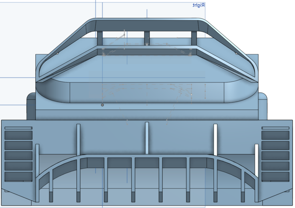
– Back of the car, including design features such as the rear diffusers and double rear wing that is present in the Yaris rally car
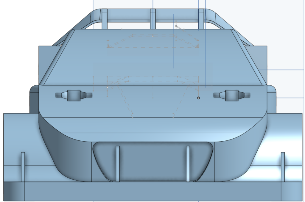
– The front of the car, with a more aggressive wide body and front aero
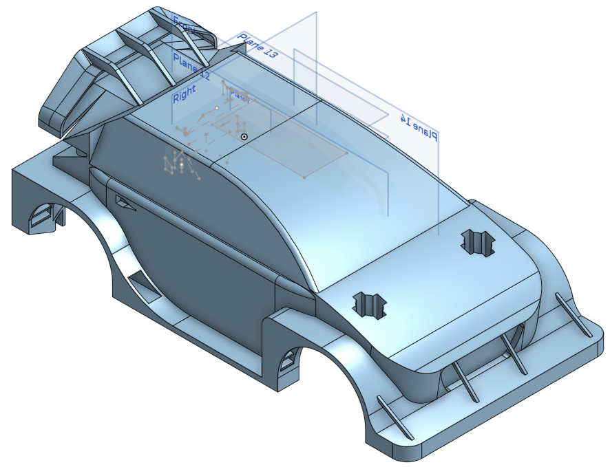
– The isometric view of the car, showing the aggressive look of the car along with the rear wing and side skirts
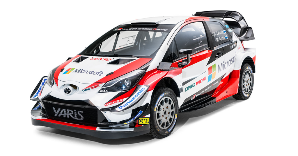
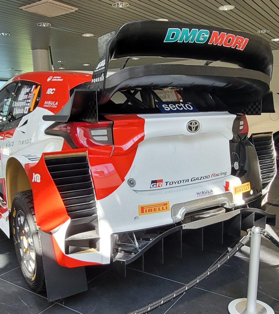
– The original Yaris car that our car was modeled after
There was also an attempt to add suspension features into the vehicle, aimed at making the vehicle better at traversing uneven terrain.
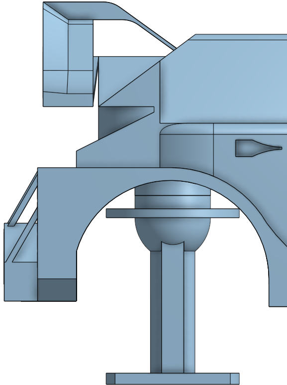
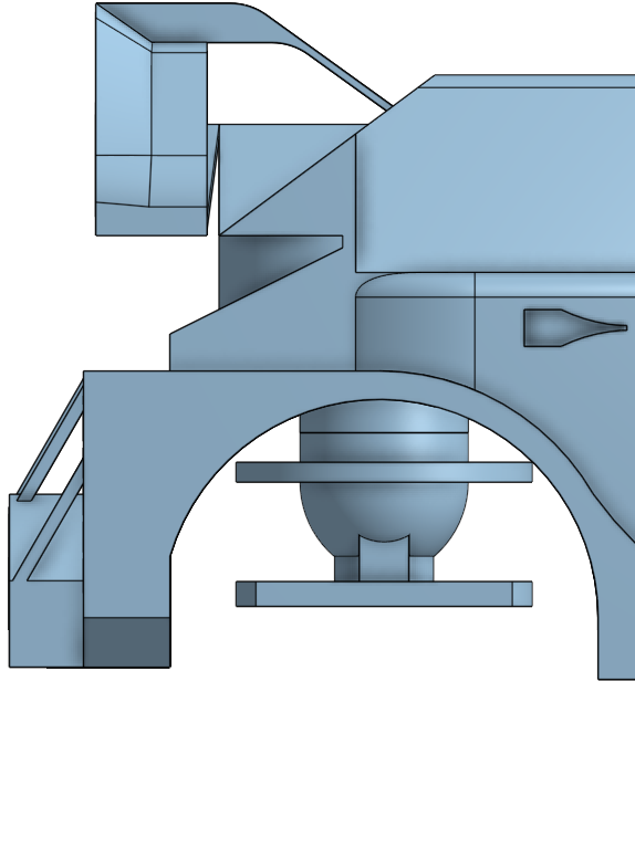
– The extended (left) and compressed (right) version of the suspension, aimed at making the car traverse terrain with more ease

const int speedM1 = 4;
const int dir1M1 = 3;
const int dir2M1 = 2;

const int speedM2 = 7;
const int dir1M2 = 6;
const int dir2M2 = 5;

const int speedM3 = 10;
const int dir1M3 = 9;
const int dir2M3 = 8;

const int speedM4 = 13;
const int dir1M4 = 12;
const int dir2M4 = 11;

void setup()
{
    pinMode(speedM1, OUTPUT);
    pinMode(dir1M1, OUTPUT);
    pinMode(dir2M1, OUTPUT);

    pinMode(speedM2, OUTPUT);
    pinMode(dir1M2, OUTPUT);
    pinMode(dir2M2, OUTPUT);

    pinMode(speedM3, OUTPUT);
    pinMode(dir1M3, OUTPUT);
    pinMode(dir2M3, OUTPUT);

    pinMode(speedM4, OUTPUT);
    pinMode(dir1M4, OUTPUT);
    pinMode(dir2M4, OUTPUT);
}

void loop(){
  // Motor 1 run
    analogWrite(speedM1, 100);
    digitalWrite(dir1M1, HIGH);
    digitalWrite(dir2M1, LOW);
  /* // Motor 2 run
    analogWrite(speedM2, 225);
    digitalWrite(dir1M2, HIGH);
    digitalWrite(dir2M2, LOW);
  // Motor 3 run
    analogWrite(speedM3, 255);
    digitalWrite(dir1M3, HIGH);
    digitalWrite(dir2M3, LOW);
  // Motor 4 run
    analogWrite(speedM4, 225);
    digitalWrite(dir1M4, HIGH);
    digitalWrite(dir2M4, LOW);
  */
}
– The original design for the circuitry and the code, with two L293D controllers controlling the four motors in the vehicle. The whole circuit is powered by a nine volt battery
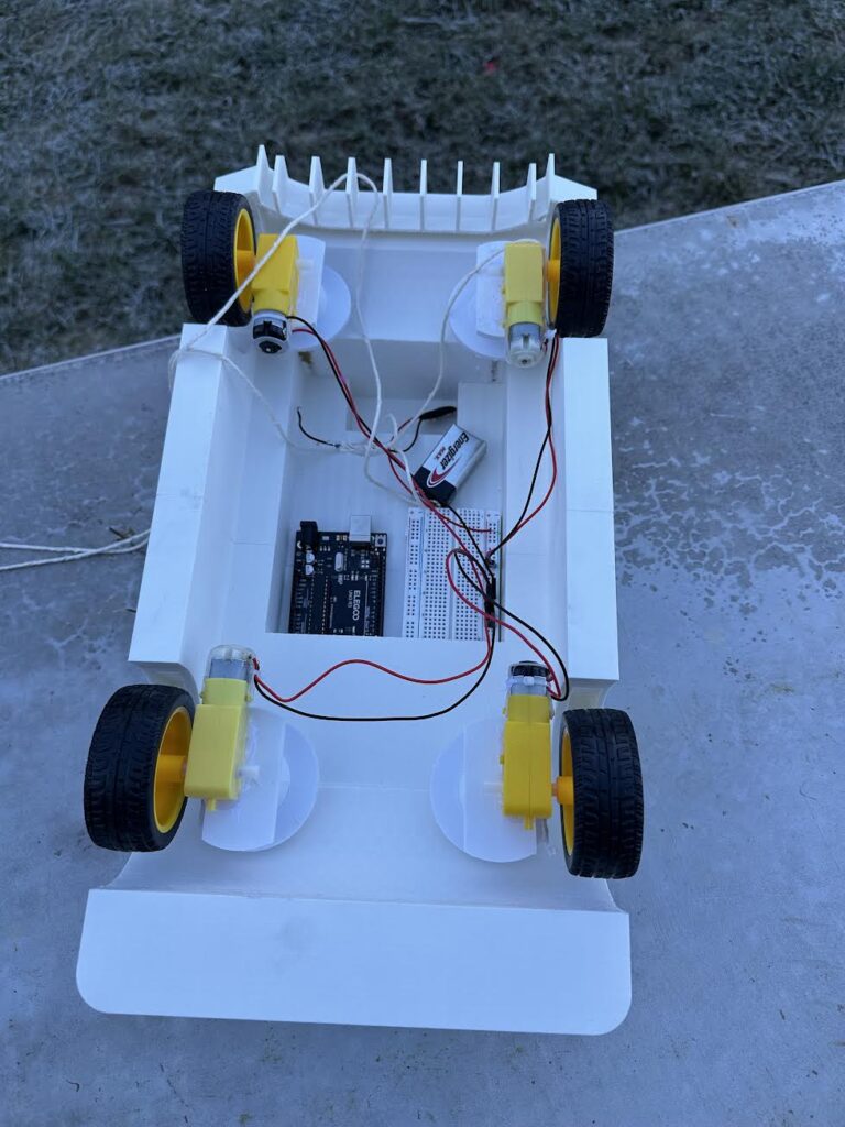
– The finished product, with a lack of suspension and motor control systems due to time and miscalculations
The finished product in the end was missing a suspension system as there were slight deviations in the 3D printed suspension parts that caused the suspension to be too tight to function properly. The motor control system was also removed and replaced with a system where the motors are directly plugged into the positive and negative ends as there wasn’t enough time to fix the erroneous motor driver system. The motors are plugged in a series circuit to decrease the current output from the battery and thus reduce the possibility of overheating the battery and low efficiency.
PT.3: TESTING
There are a total of three tests conducted, the first being the control test with the car traversing on flat ground in room temperatures, then the second being a mobility test using a tarp with water sprayed on top, and the last being a test for efficiency in cold temperatures as the vehicle traverses in cold temperatures on flat ground.
These are the links to the three tests:
- Control Test: https://drive.google.com/file/d/1YjZDfDEBEvkUMTGzhljfxRJcimuXYWeE/view?usp=drive_link
- Terrain Test: https://drive.google.com/file/d/1N4b9jPPZqc6YlLfyWRbo2S3-ntRUgrUi/view?usp=drive_link
- Cold Environment Test: https://drive.google.com/file/d/1YXSG_Ae7O9QmhzbATfRytHflUJZFh5g/view?usp=drive_link
– The first test, being a flat concrete ground at a room temperature environment (20-25 degrees Celsius)
The control test was conducted in a close to ideal environment, with minimal uneven terrain and a lack of cold temperatures to test for the ideal voltage drop of the battery. The car was ran on the ground across a distance of 293 cm three times and the voltage drop was measured using a voltmeter as a method of quantifying the energy consumption.
– The set up of the second test, with the same 293 cm length tested with rocks underneath the tarp to simulate rough terrain and water sprayed on top of the tarp to simulate slippery conditions.
The second test tested for mobility and the ability to traverse rough terrain. However, the series circuitry used to power the motors made it difficult for motors to receive adequate voltage for traversing through rough and slippery terrain, and after three tries the vehicle failed this test.
The third test (https://drive.google.com/file/d/1YXSG_Ae7O9QmhzbATfRytH flUJZFh5g/view?usp=drive_link) was conducted right next to the terrain test in a cold environment, but on flat ground, and ran for the same distance as the control test (293 cm x 3). The voltage drop was recorded and used to calculate the efficiency of the vehicle in cold temperatures (2 degrees Celsius).
PT.4: RESULTS & REFLECTION
The voltage drop for the first control trial is 0.55 volts, with the battery’s output voltage dropping from 9.00 volts to 9.45 volts. The voltage drop for the second case is 1.05 volts, from 9.05 volts to 8 volts. Assuming that similar voltage drops would mean similar power consumption, the voltage drop of the toy that was tested with the same Energizer 9V battery will be used to calculate energy consumption.
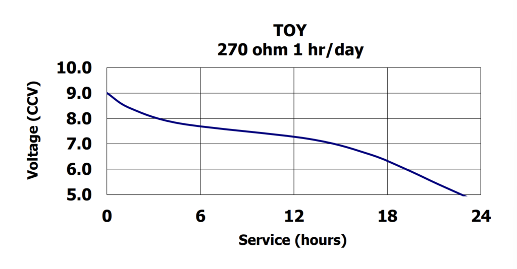
The first voltage drop from 9.00 v to 8.45 v meant that the average voltage during that duration will be around 8.725 volts, as the voltage drop from nine volts to eight and a half volts is near linear. Using the equation of V/R=IR, it can be calculated that the toy received an average of 32mA of energy. And, using P=VI, it can calculated that the toy uses 0.287 joules per second, which accounts to 1218 joules for the 1.2 hours it took to reach that voltage level. Using similar calculations, it can be found that the voltage drop from 9.05v to 9v would indicate a 2890 joules power consumption.
In order to calculate the efficiency of the vehicle, it is necessary that the energy output is calculated. However, it would be difficult for us to calculate the output, as the output would be zero joules due to how the vehicle did not gain any energy or potential energy, so the energy use in room temperature is used instead as the output energy of the vehicle doing the test in colder temperatures.
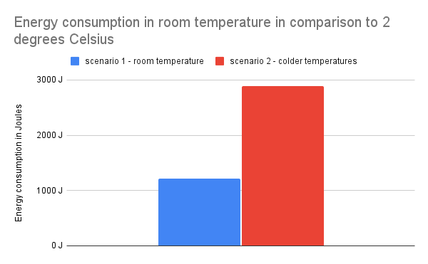
– This chart shows the differences between room temperature and cold temperature energy consumptions.
Using the formula of efficiency = energy output / energy input, it can be calculated that the efficiency of the vehicle in the cold if the energy taken in room temperature is used as the output energy would be 42.15%.
The low efficiency rate can be partially attributed to the cold temperature in the surrounding environment increasing resistance in the conductive materials inside the battery, resulting in a lower readout of voltage after cold exposure. As a result, the resultant number might not be an accurate representation of the actual efficiency, as the decrease in voltage readout could be temporary as the battery is still at a cold temperature when the voltage is being read. This effect was noticed earlier too as the batteries often showed different voltages before and after contact with colder temperatures despite not being used.
To improve on the testing procedure, the battery should be tested at a 10 minute interval after the battery came in contact with cold temperatures to show more accurate results that is more reflective of the energy consumption differences between the vehicle in room temperature versus in 2 degrees Celsius temperatures.
After analyzing the failed attempt at the terrain test, I noticed that some wheels were incapable of spinning while others are slipping on the wet surface. This could be due to the fact that the vehicle lacked a suspension system, resulting in unequal distribution of weight and thus slipping and not spinning happening at the same time. Also, the voltage per motor, being 2.25 volts, is not enough to move the car on uneven terrain and increasing the voltage input could eliminate the problem of some wheels not spinning but could not solve the slipping problem for the wheels.
To conclude these are the errors made during the test procedures:
- The battery’s voltage level was tested while it was still cold, which adds inaccuracies to the measure of energy consumption when being tested with a voltmeter.
- The lack of a suspension system decreased the vehicle’s capabilities of traversing terrain due to uneven weight distribution.
- The voltage was insufficient which resulted in some wheels being unable to spin in the terrain test.
PT.5: CHANGES TO BE MADE
To make this actually applicable on Enceladus, better heat insulation needs to be used, as the temperatures on Enceladus would make it difficult for both the circuitry to be safe and for the efficiency to be high, given the results that we got for the efficiency of the vehicle in cold temperatures that suggests the importance of heat insulation on the efficiency of the vehicle. The vehicle also needs suspension, as can be seen in how the vehicle was unable to spread weight evenly in the terrain test that simulates Enceladus terrain. More voltage for the motors would also help, as the increment of voltage would give it more power to overcome challenging terrain, given that some wheels of the prototype were not turning due to insufficient power in the terrain test. The material of the rover also needs to be changed to metals such as aluminum and iron to guarantee the structural integrity of the vehicle when traversing terrain and also increase the weight of the vehicle to make sure that it could stay on the surface of Enceladus given its weak gravitational pull. The wheels also need to be changed to incorporate spikes in order to grip into the ice better and have better traction when on ice and in a low gravity environment.
Leave a Reply