For the first project in Fusion, I chose to replicate a few parts of the engine in Onshape.
PT1: PISTON ENCASEMENT
For the first part, I chose to replicate the piston encasement, where the piston and the holes for intake, exhaust, and spark plug is located.
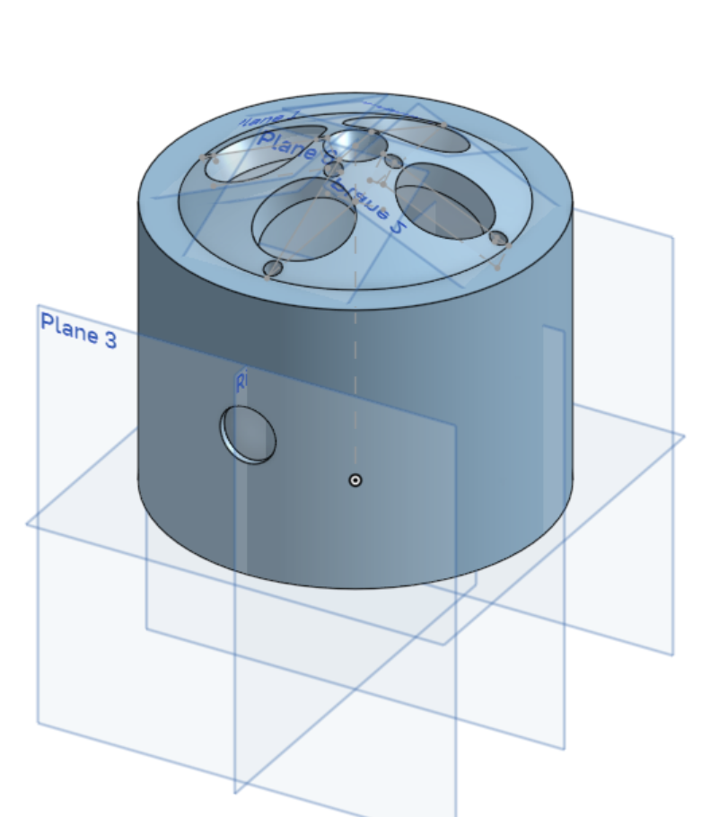
– The shape of the piston encasement.
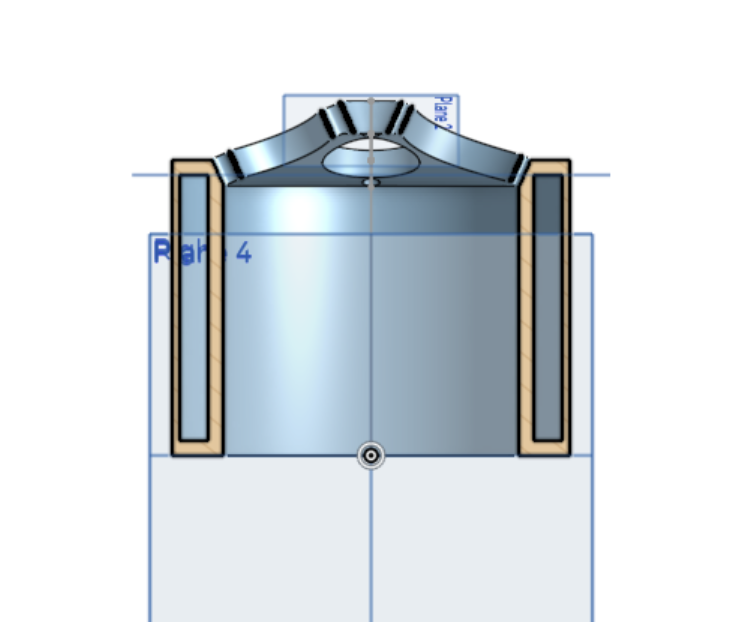
– A cross sectional view of the model, with space a hollow inside for coolant.
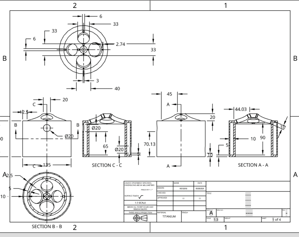
– The mechanical drawing of the encasement.

– A cross sectional view of an engine as a whole for reference.
In the end, there are still a few problems with the engine, mainly around the strength of the structure as the intake and exhaust holes take away from the structural integrity of the part. As a possible solution, the intake and exhaust holes can be located in a more inclined cone-like structure on the top of the cylinder where the piston would be. Another way to increase the structural strength is by alternating between the intake holes and exhaust holes, making the distancing between the holes constant. Also, the walls of the combustion chamber are not thick enough to resist high revving pistons and high heat.
PT2: INTAKE AND EXHAUST PIPES
The second part that I designed are the intake and exhaust pipes that stem from the encasement. The intake pipes lead intake gas from the middle of the engine to the combustion chamber, and the exhaust pipes lead the exhaust gas from the combustion chamber towards the two sides of the engine.
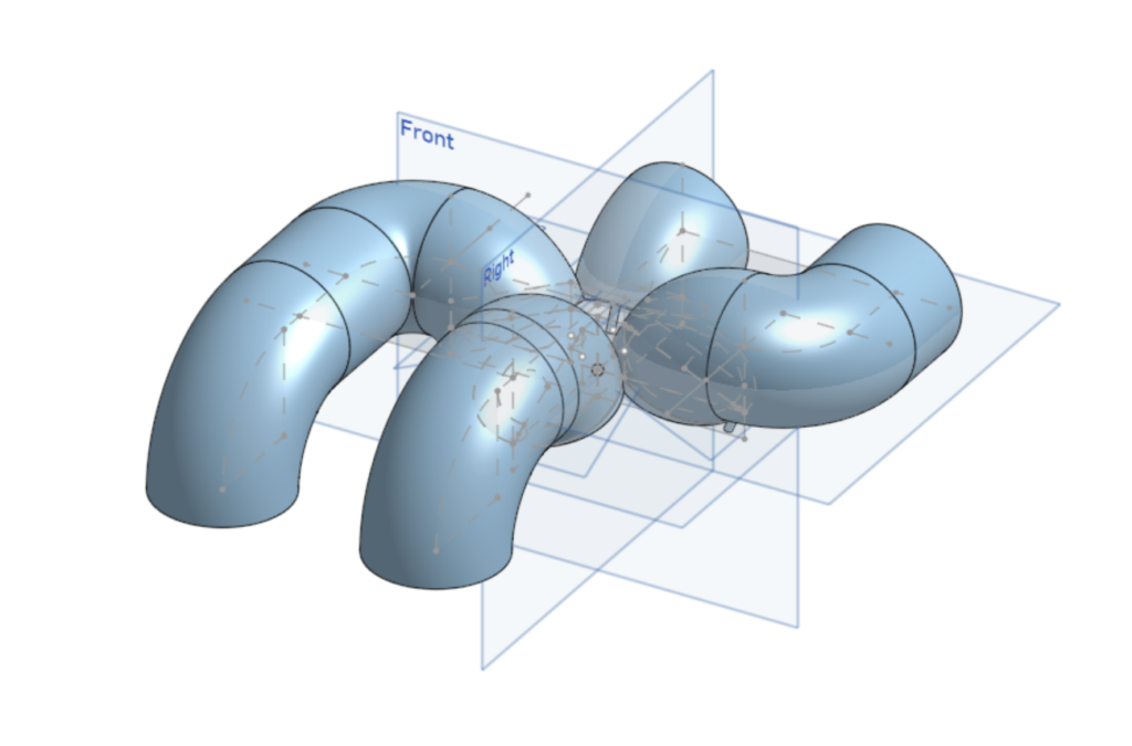
– Isometric view of the intake and exhaust pipes.
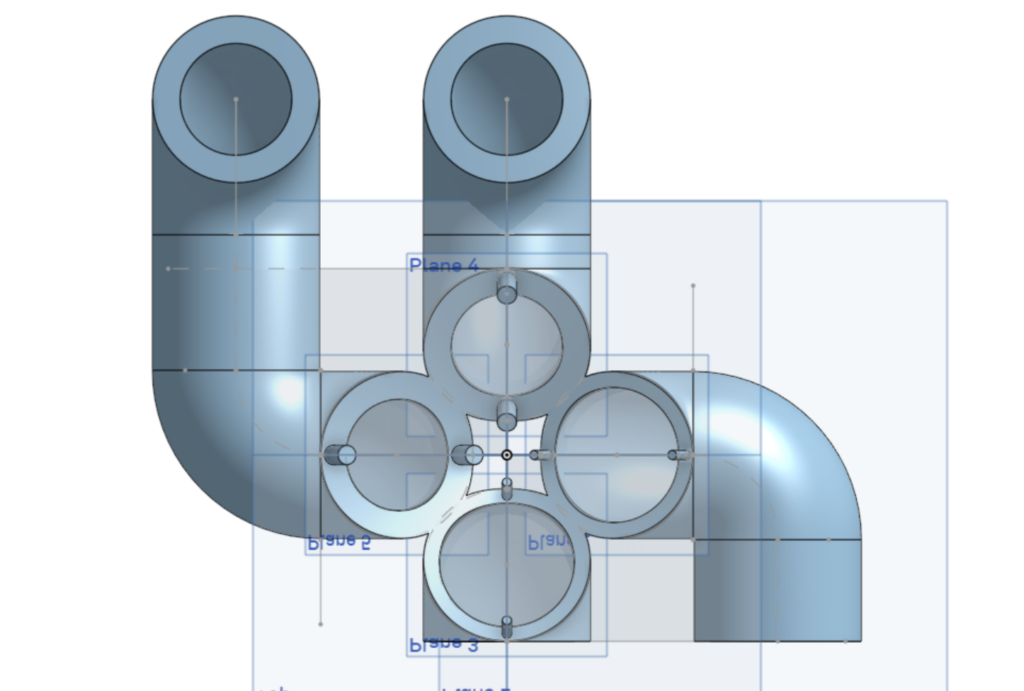
– The bottom of the pipes, showing the difference between the intake and exhaust pipes.
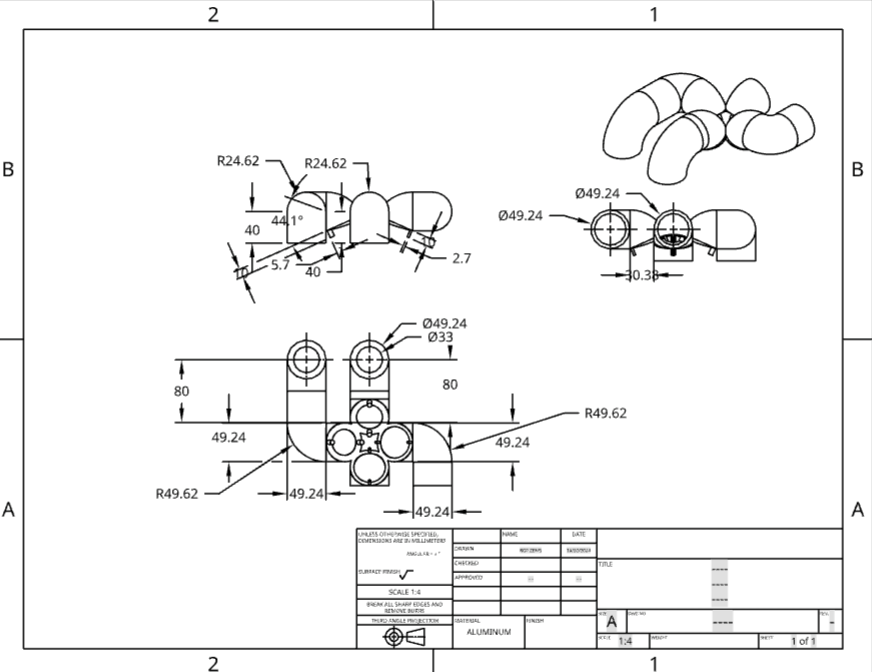
– The mechanical drawing of the intake and exhaust pipes.
The pipes are made to lock onto the encasement and are designed differently for intake and exhaust. Intake pipes are wider on the inside than the exhaust pipes, since a large volume of intake air is important for more complete combustion in the combustion chamber. An area for improvement could be the incorporation of the spray head for fuel in the intake pipes and also for the valves that control the opening and closing of the intake and exhaust holes. Also, the walls for the exhaust pipes could be reduced, as increased thickness could mean excessive weight. The positioning of the pipes could also be enhanced, as the pipes could be reduced in total length to reduce even more weight.
PT3: ENGINE BLOCK
The third and last part of the project is the engine block, which houses the encasement, pipes, and provides tubes for coolant coming both in and out of the encasement.
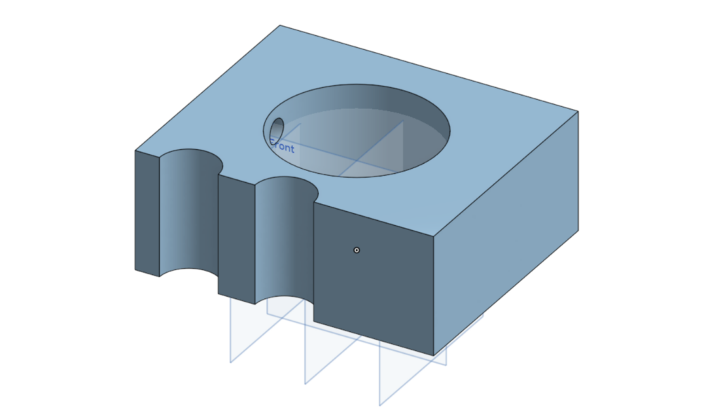
– The isometric view of the engine block.
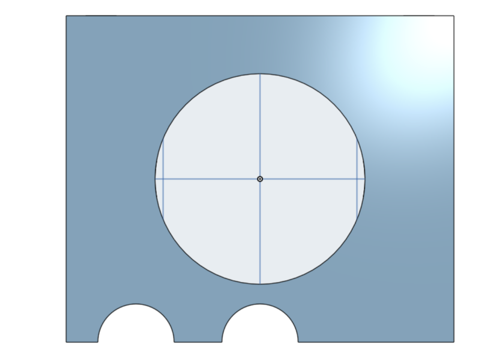
– The top view of the engine block.
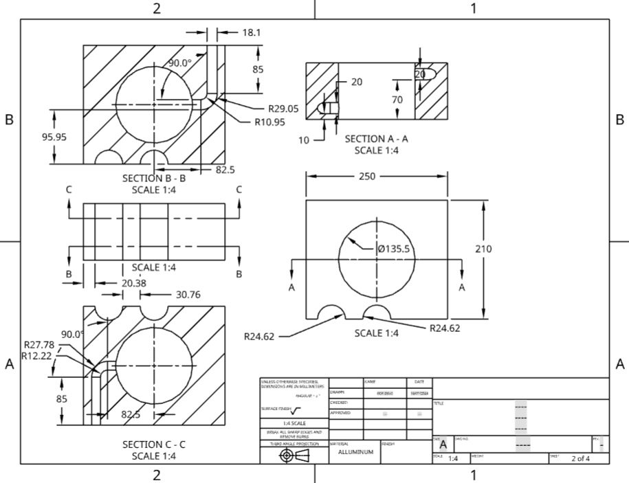
– The mechanical drawing of the engine block.
The engine block is simplified in this model, as it doesn’t need to incorporate more complex features such as the camshaft, crankshaft, valves, etc. However, it still holds together the two parts previously mentioned. The engine block could also be made more hollow to decrease weight and to incorporate more internal structures.
PT4: ASSEMBLY
Together, the three parts form one of the most important portions of the engine.
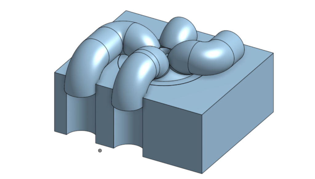
– The isometric view of the three parts combined.
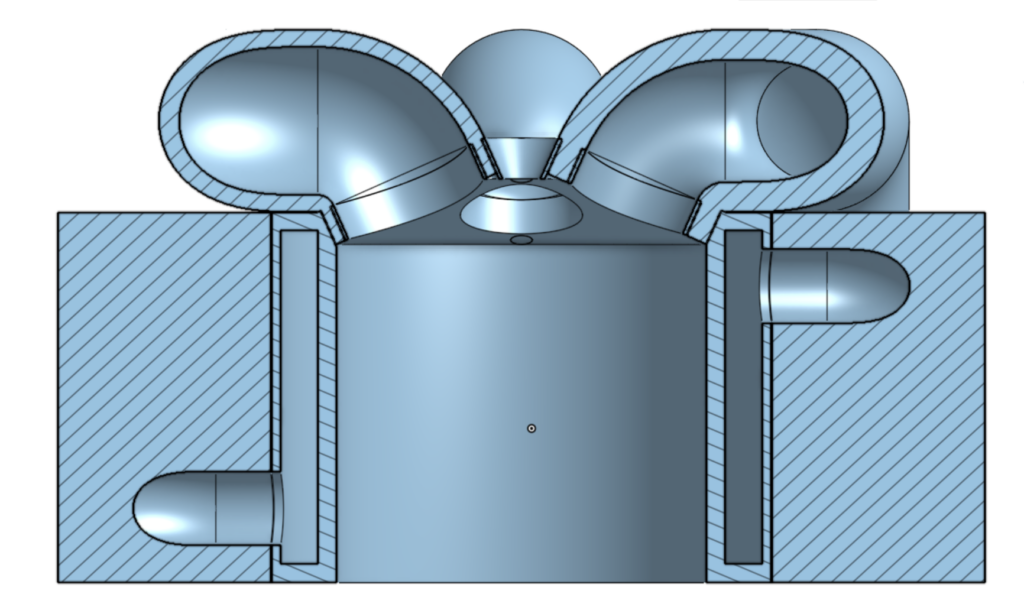
– A cross sectional view that shows the cooling system in both the encasement and the engine block.
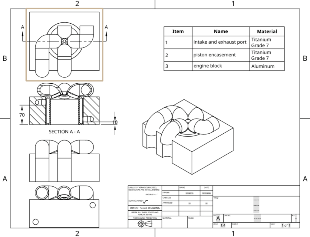
– The mechanical drawing of the assembly.
PT.5: CONCLUSION
Despite the fact that a lot of the parts still have room for improvement, the project still acts as a general model for the insides of an engine, and could be built on in further projects to create a more complete model.
Leave a Reply