Music has always been an important part of my life, and it’s something I listen to everyday, whether I need to relax or find motivation. The rhythm and energy of beats have a way of bringing focus and emotions together, and inspired me to incorporate a music element into this project. For this project, I wanted to design a simple robot that could detect hand movements, respond dynamically, and perform an expressive action by drumming to the rhythm of my hand movements.
Project Overview
The Gesture Drum bot uses the user’s hand as a virtual conductor. And when their hand moves toward or away from the ultrasonic sensor in rhythm, the Arduino measures these distance changes and creates a beat.
Each time a beat is detected:
- The servo taps like a drumstick
- The buzzer plays a short musical note with a random
- The LCD screen briefly flashes “BEAT!” and then updates the BPM
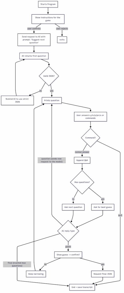
Tinkercad Design
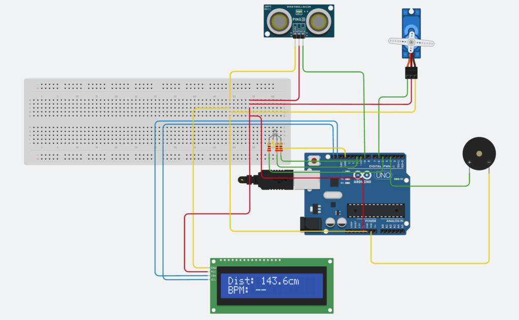
Image of Circuit Design in Tinkercad
I started by designing and simulating a prototype in Tinkercad. This process helped me to first verify the logic of the code and wiring for different components.
The wires in the circuit design are also color coded to make it more accessible:
Green – PINs
Yellow – Ground
Red – Power (5V)
Blue – SDA / SCL
Circuit Wiring
| Component | PIN connection | Function |
| Ultrasonic Sensor | VCC -> 5V, GND -> GND, SIG -> D9 | Measures hand distance |
| Servo Motor | SIG -> D6, VCC -> 5V, GND -> GND | Moves motor based on the distance |
| Piezo Buzzer | (+) -> D3, (-) -> GND | Plays random tone when beat triggered |
| LCD | SDA -> A4, SCL -> A5, VCC -> 5V, GND -> GND | Displace distance and BPM. |
Above is the schematic diagram of the circuit design. Where it illustrates how all the components are connected to each other and the Arduino board.
Bill of Materials (BOM)
| Component | Quantity | Description |
| Arduino UNO | 1 | Main board |
| Ultrasonic Distance Sensor | 1 | Detects distance of hand movement |
| Servo Motor | 1 | acts as drumstick arm |
| Piezo Buzzer | 1 | plays a tone for each beat |
| PCF8574-based, 32 (0x20) LCD 16 x 2 (I2C) | 1 | displays data |
| LCBG LED RGB | 1 | LED that can display any color |
| 1 kΩ Resistor | 3 | resistor for LED |
| BreadBoard + Jumper Wires | – | for connections |
Code Logic
Entire Source Code
#include <Servo.h>
#include <LiquidCrystal_I2C.h>

LiquidCrystal_I2C lcd(0x20, 16, 2);
Servo arm;

//pins
const int ultrasonic_pin = 9;
const int servo_pin = 6;
const int buzzer_pin = 3;

//window
const int min_dist = 60;
const int max_dist = 150;

//beat
float lastDistance = 0;
float lastVelocity = 0;
bool approaching = false;

unsigned long lastBeat = 0;
const unsigned long min_beat_gap = 250;

//BPM
unsigned long history[4] = {0};
int Pos = 0;
bool Full = false;
float bpm = 0;

//Notes
const int notes[] = {196,220,247,294,330,392,440,494};
const int note_count = sizeof(notes) / sizeof(int);

void setup() {
  Serial.begin(115200);

  pinMode(buzzer_pin, OUTPUT);
  digitalWrite(buzzer_pin, LOW);

  //setup lcd
  lcd.init();
  lcd.backlight();
  lcd.clear();

  //reset servo position
  arm.attach(servo_pin);
  arm.write(90);

  randomSeed(analogRead(A0));
  //start timer
  lastBeat = millis();

}

void loop(){
  unsigned long now = millis();

  //Read distance
  float dist = readDistanceCM();
  //positive value, continues
  bool valid = (dist>0);

  if (valid){
    //servo follows hand
    arm.write(distanceToAngle(dist));
  }

  //Detect beat
  float velocity = lastDistance - dist;
  //within the window that we defined
  bool inRange = (dist >= min_dist && dist <= max_dist);

  //valid hand movement, continues
  if (inRange && velocity > 0.4) {
    approaching = true;
  }

  //for detecting hand movement coming back
  bool reversed = (lastVelocity > 0 && velocity < 0);

  if (valid && approaching && reversed && (now - lastBeat > min_beat_gap)){
    triggerBeat();
    record(now);
    approaching = false;
  }

  lastVelocity = velocity;
  lastDistance = dist;

  //lcd
  static unsigned long lastLCD = 0;
  if (now - lastLCD > 200) {
    lastLCD = now;
    updateLCD(valid ? dist : -1, bpm);
  }

  delay(15);

}


float readDistanceCM() {
  pinMode(ultrasonic_pin, OUTPUT);
  digitalWrite(ultrasonic_pin, LOW);
  delayMicroseconds(2);
  digitalWrite(ultrasonic_pin, HIGH);
  delayMicroseconds(10);
  digitalWrite(ultrasonic_pin, LOW);

  //echo
  pinMode(ultrasonic_pin, INPUT);
  unsigned long dur = pulseIn(ultrasonic_pin, HIGH, 15000);

  if (dur==0) return -1;

  float cm = dur / 58.0;
  if (cm < 2 || cm > 400) return -1;

  return cm;
}


int distanceToAngle(float cm) {
  //detect distance inside the window
  if (cm < min_dist) cm = min_dist;
  if (cm > max_dist) cm = max_dist;

  //convert distance to servo angle
  float t = (cm - min_dist) / (max_dist - min_dist);
  return 35 + (int)(t*(120-35));
}

void triggerBeat() {
  int note = notes[random(note_count)];
  tone(buzzer_pin, note, 120);
  lastBeat = millis();
}

void record(unsigned long now) {
  unsigned long x = now - lastBeat;
  history[Pos] = x;
  Pos = (Pos + 1) % 4;

  //true once we have stored 4 intervals
  if (Pos == 0) Full = true;

  if (Full) {
    unsigned long sum = 0;
    for (int i=0; i<4; i++) {
      sum += history[i];
    }

    float avg = sum / 4.0;
    bpm = 60000.0 / avg;

  }
}

void updateLCD(float dist, float bpm) {
  //print distance
  lcd.setCursor(0, 0);
  if (dist < 0) {
    lcd.print("Dist: --       ");
  } else {
    lcd.print("Dist: ");
    lcd.print((int)dist);
    lcd.print("cm    ");
  }

  lcd.setCursor(0, 1);
  lcd.print("BPM: ");
  if (bpm > 0) lcd.print((int)bpm);
  else lcd.print("--");
  lcd.print("       ");
}- Read distance: The ultrasonic sensor measures hand distance.
- Filter Noise: A smoothing algorithm for the ultrasonic sensor to remove inconsistent values that might affect consistency
- Detect Beat: If the hand moves toward the sensor and then reverses direction quickly, then it’s considered to a beat.
- Play Beat: After a beat is detected, the system will react to it by playing a random musical note using tone(), and move the servo slightly as a drum tap.
- Calculate BPM: The program stores the last few beat intervals and averages them.
- Display Data: The LCD continuously updates to show distance and BPM.
Code Explanation
void setup() {
  Serial.begin(115200);

  pinMode(buzzer_pin, OUTPUT);
  digitalWrite(buzzer_pin, LOW);

  //setup lcd
  lcd.init();
  lcd.backlight();
  lcd.clear();

  //reset servo position
  arm.attach(servo_pin);
  arm.write(90);

  randomSeed(analogRead(A0));
  //start timer
  lastBeat = millis();

}
The program starts with the setup() function, which runs once when the program is uploaded to Arduino. It includes all of the libraries needed and initializes all the variables.
Serial.begin(115200);This line starts a serial port at 115200, which acts as the console and allows Arduino to send debugging messages. In addition, pinMode() sets up the buzzer’s pin so it can send sound signals. The parameters of it are the pin number and the mode (output / input).
diginalWrite(<pin>, LOW) turns off the buzzer at the start so it doesn’t make any sound when the program starts. With digitalWrite(), you are able to either set it as High (5V) or Low (0V).
Afterwards, the LCD display get initialized. And the servo is configured at a specific pin.
The code now proceeds to the loop() function which runs over and over again.
unsigned long nowMs = millis();millis() is a built in function that returns the number of milliseconds since the program started running. And in this case, it is assigned and stored in a variable called nowMs, and is used throughout the loop for timing things like detecting the beat and stuff.
  //Read distance
  float dist = readDistanceCM();
  //positive value, continues
  bool valid = (dist>0);

//read distance function
float readDistanceCM() {
  pinMode(ultrasonic_pin, OUTPUT);
  digitalWrite(ultrasonic_pin, LOW);
  delayMicroseconds(2);
  digitalWrite(ultrasonic_pin, HIGH);
  delayMicroseconds(10);
  digitalWrite(ultrasonic_pin, LOW);

  //echo
  pinMode(ultrasonic_pin, INPUT);
  unsigned long dur = pulseIn(ultrasonic_pin, HIGH, 15000);

  if (dur==0) return -1;

  float cm = dur / 58.0;
  if (cm < 2 || cm > 400) return -1;

  return cm;
}
This section is in charge of reading the distance from the ultrasonic sensor and smoothening the data received. This is achieved by first creating a floating variable and calling the readDistanceCM() function to store the distance returned inside it. Afterwards, a boolean variable is created to check if the reading make sense. And if valid, the distance is passed on to convert it to an angle.
  //Servo follows
  if (valid) {
    int targetAngle = distanceToAngle(emaDist);
    arm.write(targetAngle);
  }

//function to convert distance to angle
int distanceToAngle(float cm) {
  //detect distance inside the window
  if (cm < min_dist) cm = min_dist;
  if (cm > max_dist) cm = max_dist;

  //convert distance to servo angle
  float t = (cm - min_dist) / (max_dist - min_dist);
  return 35 + (int)(t*(120-35));
}
If the distance is valid, it converts it to an angle that can be passed on to the servo using the distanceToAngle function.
 //Detect beat
  float velocity = lastDistance - dist;
  //within the window that we defined
  bool inRange = (dist >= min_dist && dist <= max_dist);

  //valid hand movement, continues
  if (inRange && velocity > 0.4) {
    approaching = true;
  }
This section is responsible for detecting whether the hand is moving toward the sensor fast enough to count as a beat gesture.
dist is the distance from the ultrasonic sensor. lastDistance is the previous loop’s distance, and is stored to compare how much the distance changed since then. In other words, if the hand moves quickly, the difference between those two values becomes bigger.
velocity = lastDistance - dist;Therefore, the formula above gives an estimate of how fast the hand is moving. If the hand moves closer to the sensor, then emaDist (current distance) becomes smaller, lastDistance – dist becomes positive, and this represents positive velocity, vice versa.
//within the window that we defined
  bool inRange = (dist >= min_dist && dist <= max_dist);

  //valid hand movement, continues
  if (inRange && velocity > 0.4) {
    approaching = true;
  }
The window min and max defines the detection zone that we actually consider about, if the hand isn’t in this zone, we ignore the movement, and this is used to prevent false triggers. And approaching is simply a boolean variable that is true when the hand is inside this distance zone.
if (valid && approaching && reversed && (now - lastBeat > min_beat_gap)){
    triggerBeat();
    record(now);
    approaching = false;
  }
Finally, the if statement considers whether the hand is inside the valid distance zone and is moving toward the sensor fast enough, if so, it triggers a beat by calling that function.
float readDistanceCM() {
  pinMode(ultrasonic_pin, OUTPUT);
  digitalWrite(ultrasonic_pin, LOW);
  delayMicroseconds(2);
  digitalWrite(ultrasonic_pin, HIGH);
  delayMicroseconds(10);
  digitalWrite(ultrasonic_pin, LOW);

  //echo
  pinMode(ultrasonic_pin, INPUT);
  unsigned long dur = pulseIn(ultrasonic_pin, HIGH, 15000);

  if (dur==0) return -1;

  float cm = dur / 58.0;
  if (cm < 2 || cm > 400) return -1;

  return cm;
}
Next up, this function is in charge of calculating the distance from the hand. The logic of it is to first send a short ultrasonic pulse, and wait for the echo to return. And by using this data, it is able to convert that time into a distance measurement.
float dist = readDistanceCM();We have actually mentioned it previously, and called it to store it inside the dist variable.
pinMode(ULTRA_PIN, OUTPUT);
digitalWrite(ULTRA_PIN, LOW);
delayMicroseconds(2);
digitalWrite(ULTRA_PIN, HIGH);
delayMicroseconds(10);
digitalWrite(ULTRA_PIN, LOW);
This line first allows assigns a pin and mode for the sensor. And create a pulse starting with low for 2 microseconds, high for 10 microseconds, and back to low again.
pinMode(ULTRA_PIN, INPUT);After that, it immediately switched to input mode to listen for the echo returning.
unsigned long dur = pulseIn(ULTRA_PIN, HIGH, 15000UL);
float cm = dur / 58.0;
Finally, this standard formula converts the echo received into distance in centimeters.
Above, I have explained all the essential parts of the code. Most of the program’s logic is organized inside the main loop, but to keep the code cleaner and easier, I moved any repeated or commonly used operations into separate functions.
Physical Prototype:
While I really want to build the project out in real life on a real Arduino board, my computer unfortunately couldn’t detect the port connected to it. I plan on fixing this issue, and once it’s revolved, I’ll update this post with a demonstration of the physical prototype.
For now, the Tinkercad prototype functions perfectly, and as a reader, you are able to replicate the project with the wiring and code provided.
Benefits of making a physical prototype:
Right now, when running the code online in Tinkercad, I’ve noticed some lag and unresponsiveness. And by compiling the code on a real Arduino board, this issue can be eliminated. Moreover, building a physical prototype provides a more engaging and realistic experience, as you are able to interact with it directly and can have a better user experience.
Reflections on AI
I used GPT-5 as my AI assistant throughout this project. I chose to use GPT not only because I am more familiar with it, but also because it knows me better in terms of my working style and preferences. Over time, it has learned about my personality and requirements stored as a memory, allowing it to provide to responses that I feel more suitable for me.
And in the project, I used AI for a lot of several tasks. This includes: debugging, suggesting better algorithms, and polishing my wording of this blog post to make it sound a bit smoother. In addition, since it had been a while since I last programmed with arduino, I have asked it for guidance on parts of the code.
I chose to use AI because it helps me to save time, while still allowing active learning for myself through problem solving, thinking creatively, and deepen my understanding of coding.
Source Code
#include <Servo.h>
#include <LiquidCrystal_I2C.h>

LiquidCrystal_I2C lcd(0x20, 16, 2);
Servo arm;

//pins
const int ultrasonic_pin = 9;
const int servo_pin = 6;
const int buzzer_pin = 3;

//window
const int min_dist = 60;
const int max_dist = 150;

//beat
float lastDistance = 0;
float lastVelocity = 0;
bool approaching = false;

unsigned long lastBeat = 0;
const unsigned long min_beat_gap = 250;

//BPM
unsigned long history[4] = {0};
int Pos = 0;
bool Full = false;
float bpm = 0;

//Notes
const int notes[] = {196,220,247,294,330,392,440,494};
const int note_count = sizeof(notes) / sizeof(int);

void setup() {
  Serial.begin(115200);

  pinMode(buzzer_pin, OUTPUT);
  digitalWrite(buzzer_pin, LOW);

  //setup lcd
  lcd.init();
  lcd.backlight();
  lcd.clear();

  //reset servo position
  arm.attach(servo_pin);
  arm.write(90);

  randomSeed(analogRead(A0));
  //start timer
  lastBeat = millis();

}

void loop(){
  unsigned long now = millis();

  //Read distance
  float dist = readDistanceCM();
  //positive value, continues
  bool valid = (dist>0);

  if (valid){
    //servo follows hand
    arm.write(distanceToAngle(dist));
  }

  //Detect beat
  float velocity = lastDistance - dist;
  //within the window that we defined
  bool inRange = (dist >= min_dist && dist <= max_dist);

  //valid hand movement, continues
  if (inRange && velocity > 0.4) {
    approaching = true;
  }

  //for detecting hand movement coming back
  bool reversed = (lastVelocity > 0 && velocity < 0);

  if (valid && approaching && reversed && (now - lastBeat > min_beat_gap)){
    triggerBeat();
    record(now);
    approaching = false;
  }

  lastVelocity = velocity;
  lastDistance = dist;

  //lcd
  static unsigned long lastLCD = 0;
  if (now - lastLCD > 200) {
    lastLCD = now;
    updateLCD(valid ? dist : -1, bpm);
  }

  delay(15);

}


float readDistanceCM() {
  pinMode(ultrasonic_pin, OUTPUT);
  digitalWrite(ultrasonic_pin, LOW);
  delayMicroseconds(2);
  digitalWrite(ultrasonic_pin, HIGH);
  delayMicroseconds(10);
  digitalWrite(ultrasonic_pin, LOW);

  //echo
  pinMode(ultrasonic_pin, INPUT);
  unsigned long dur = pulseIn(ultrasonic_pin, HIGH, 15000);

  if (dur==0) return -1;

  float cm = dur / 58.0;
  if (cm < 2 || cm > 400) return -1;

  return cm;
}


int distanceToAngle(float cm) {
  //detect distance inside the window
  if (cm < min_dist) cm = min_dist;
  if (cm > max_dist) cm = max_dist;

  //convert distance to servo angle
  float t = (cm - min_dist) / (max_dist - min_dist);
  return 35 + (int)(t*(120-35));
}

void triggerBeat() {
  int note = notes[random(note_count)];
  tone(buzzer_pin, note, 120);
  lastBeat = millis();
}

void record(unsigned long now) {
  unsigned long x = now - lastBeat;
  history[Pos] = x;
  Pos = (Pos + 1) % 4;

  //true once we have stored 4 intervals
  if (Pos == 0) Full = true;

  if (Full) {
    unsigned long sum = 0;
    for (int i=0; i<4; i++) {
      sum += history[i];
    }

    float avg = sum / 4.0;
    bpm = 60000.0 / avg;

  }
}

void updateLCD(float dist, float bpm) {
  //print distance
  lcd.setCursor(0, 0);
  if (dist < 0) {
    lcd.print("Dist: --       ");
  } else {
    lcd.print("Dist: ");
    lcd.print((int)dist);
    lcd.print("cm    ");
  }

  lcd.setCursor(0, 1);
  lcd.print("BPM: ");
  if (bpm > 0) lcd.print((int)bpm);
  else lcd.print("--");
  lcd.print("       ");
}