For this project, my group and I designed and created a working rover made specifically for Trappist-1e; its terrain, environment, and atmosphere. In this blog post, we will discuss our process: how we initially decided on the design and purpose of the vehicle.
Additionally, it is worth noting that this project required scientific calculations that will be elaborated on later in this post.
Problem: Trappist-1e is a difficult planet to traverse.
Definition Statement: We need to build a vehicle that can withstand Trappist-1e’s extreme contrasting temperatures, traverse the uneven and rocky terrain, and endure the immense radiation emitted by Trappist-1e’s star. Additionally, the vehicle must be large enough to hold at least four individuals and have a large enough fuel container to travel 10km, unless powered by another source (advanced radiation solar power).
Material List (because why not)
1× 4×AA battery holder (6V total)
4× AA batteries (fresh)
1× SPST switch (slide or toggle) rated at least 1A is ideal
Motors + wiring
6× DC gear motors (yellow TT motors are perfect)
Hookup wire (22–26 AWG is fine)
You can use 2 colors: red for +, black for –
Wire stripper / scissors
Electrical tape or heat shrink or soldering kit (any one method to secure connections)
Small breadboard
Zip ties for cable management
Research stage
Researching is the most important key step before preparing to build anything. Luckily, me and my group conducted a significant amount of research prior to the start of this particular project. If you would like to learn more about Trappist-1e, I did an entire blog post revolved around it and you’re free to check it out.
Brainstorming Stage
This stage required maximum effort from everyone in the group. Over the course of multiple classes, my group mates and I came up with many ideas that could work. Here are a few of our authentic ideas with respective problems that follow:
Radiation Powered Rover:
Using advanced solar power technology, our vehicle will be able to run off of Trappist-1e’s immense amount emitted radiation.
Problems with idea:
There could potentially be an atmosphere nullifying the emitted radiation, ultimately prevented the vehicle from functioning.
Motorcycle with Body
A motorcycle (2 wheels) covered in a body full of advanced solar panels (collecting radiation for power assuming its powered by the radiation). This would allow for a more swift and fun way to traverse Trappist-1e while also required less materials than a larger sized rover.
Problems with idea:
There will most likely be less stability when riding the vehicle. Additionally, although it would take minimal materials to create one motorcycle, creating multiple motorcycles for multiple people would all require more materials than a rover would need.
Brainstorming Stage 2
Traction Wheels:
Traction wheels can be implemented for simple and easy traversal across Trappist-1e’s rocky and uneven terrain. We will use a rocker bogie system to allow additional flexibility.
Problems with idea:
The material of the traction wheels could possibly increase the vehicles conductivity depending on Trappist-1’s (the star of Trappist-1e) impact on Trappist-1e (radioactivity, electromagnetic energy, other aspects).
Nuclear Battery Back at Base:
Whenever the vehicle is resting at our base residing on Trappist-1e, it will charge via a nuclear battery assuming that the advanced radiation solar panel technology doesn’t work.
Problems with idea:
Having a nuclear battery at base could be harmful when considering living conditions. Possibly implementing a separate charging station could be better for health standards.
Our decision
We as a group decided to stick with the traction wheels and advanced solar technology while scrapping the nuclear battery and motorcycle idea.
Here is a description of the vehicle we hoped to create (we wouldn’t actually implement the radiation powered solar panels into our physical vehicle design; the audience is meant to assume that it is there):
A six-wheeled, radiation-powered electric vehicle designed to travel 10km without refuelling on the planet Trappist 1-e. This exoplanet faces challenges like a dim red dwarf, dust-filled air, rocky terrain, temperature extremes. Additionally, there are possible radiation bursts from its star, which we will use to our advantage in order to power the vehicle.
Radiation-charged energy system: This vehicle relies on advanced solar power technology to collect radiation and convert it into usable energy.
Rocker Bogie System: a six-wheeled rocker bogie system which helps traverse uneven and rocky terrain. Wide and high grip wheels: Thick and wide tires with deep treads, but still compatible with suspensions.
Creating Stage
This stage took the longest amount of time. We all acknowledged our different strengths and weaknesses, working on aspects of the vehicle we were more comfortable/stronger with.
Out of CAD and circuits, I was more comfortable doing CAD. I did a significant amount of work on the vehicle itself using OnShape (CAD), creating the rocker bogie system parts and screws. I thought I did quite well, considering my minimal experience with CAD. I had low expectations for myself and was surprisingly pleased with how the design for our rocker bogie system turned out.
Implementing the rocker bogie system into our vehicle design was essential considering the terrain we would be facing on Trappist-1e would require stability and balance. Our design was a more simplistic version of a rocker bogie system while still maintaining the same function as a regular system.
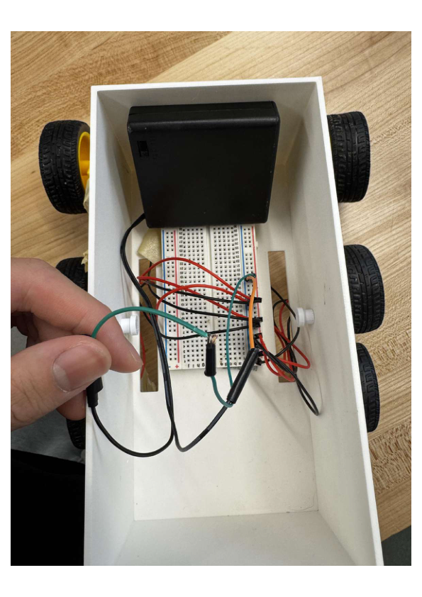
The body of our vehicle was going to be a box with small rectangular holes at the bottom of the sides to allow wires (from the motors attached to the wheels) to attach to the circuit located within the box. I’m sorry if that bit sounded a bit complicated, but thats the most simple way I can explain it. However, there are images of the vehicle and the separate parts in the stage down below.
Creating Stage CAD: Images and Explanations
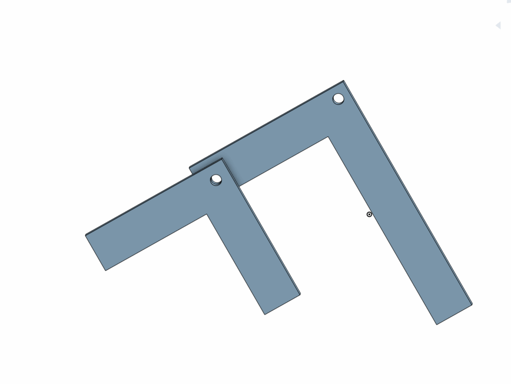
ROCKER BOGIE SYSTEM: The image above is the rocker bogie system. The smaller body acts as the bogie, and the larger body acts as the rocker. The small holes are connected via screws (also made on CAD, image below). With wheels attached at the bottom of the legs of the bodies, the vehicle can traverse through rough terrain and over steep hills.
We 3d printed two small bodies and 2 large bodies, one of each for both sides of the body of the vehicle.
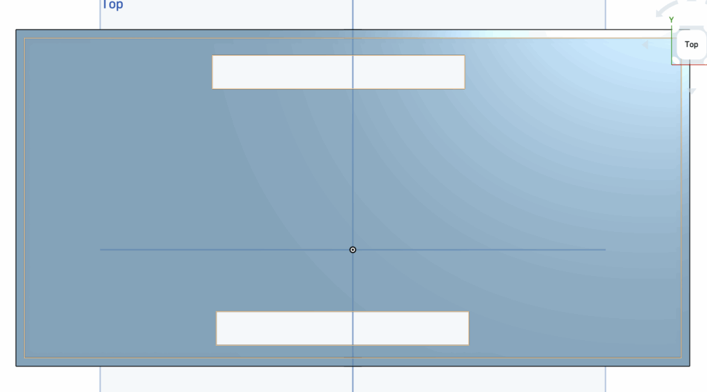
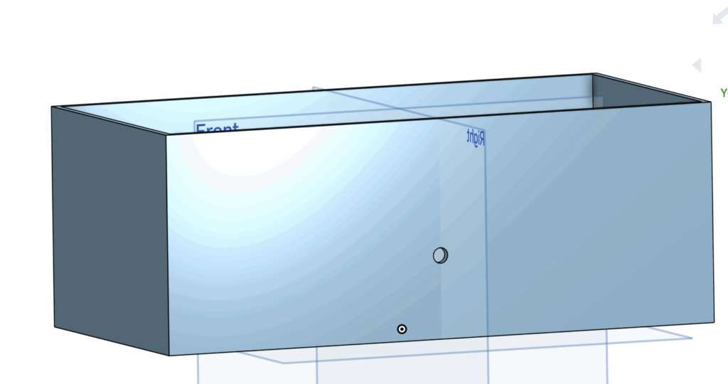
BODY OF VEHICLE (SHELL): The two images above are different angles of the body of our vehicle.
The first image is looking down at the body (top perspective). As previously mentioned, there are two rectangular holes located on different sides for wires attached to the circuit to connect to the motors and wheels.
The second image is looking at the side of the vehicle. The body is a rectangular prism with an opening at the top for easy access to the circuit and all the other components within the body. The hole(s) on the side of the vehicle connect the rocker bogie system to the body via screws.
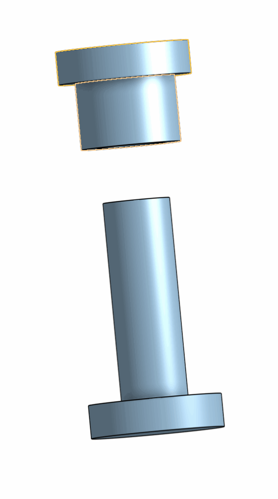
SCREWS: The image above is 1 of 4 screws we used to connect the rocker bogie system parts together and onto the body.
We measured the diameter of the screws to be partially smaller than the diameter of the holes on the rocker bogie system and the body so there wouldn’t be any fitting difficulties. In case of the screws falling out of the holes due to this minor change in diameter, we added super glue to the screws so that nothing would fall off.
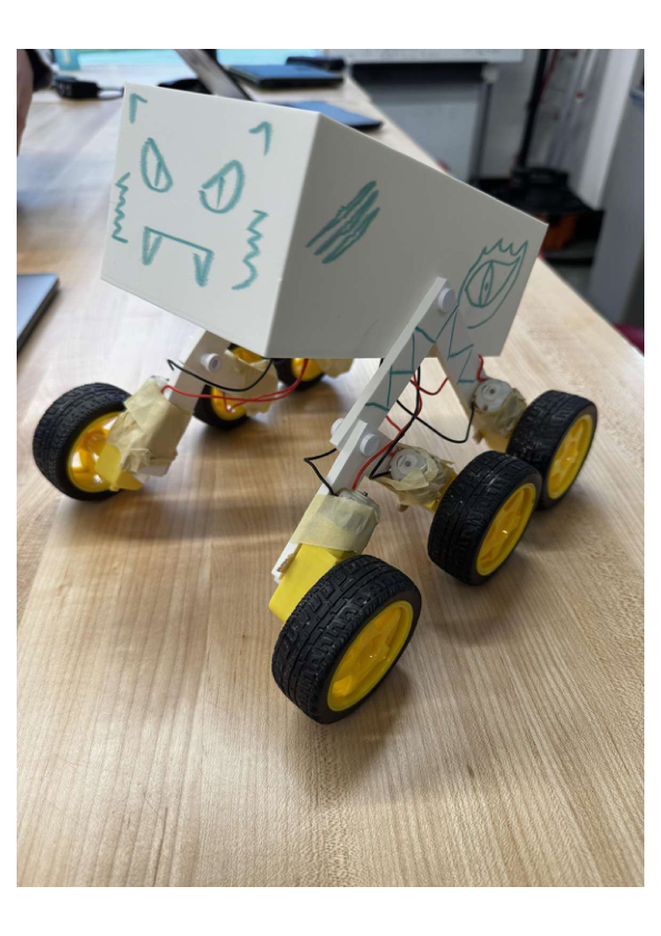
THE VIPER: The image above is what our vehicle turned out to look like. We called it “The Viper”, and yes, we added a face and other cool details/features to make it seem more “alive”. As you can tell, the rocker bogie system is tightly screwed on to each side of the body, with wheels and motors attached to each of the legs. The vehicle is well balanced and stable, which is exactly what we as a group aimed for when creating its design. We were satisfied with its design and its ability to traverse all types of surfaces with ease.
Testing Stage (Science Aspect Included; Calculating Efficiency)
Testing was fun because we experimented with different environments and terrain.
For each testing day, we recorded the voltage of the 4 AA batteries before and after the test, the distance the vehicle would be travelling, the time it took for the vehicle to travel the respective distance, the current at different time blocks, and the mass of the vehicle. Additionally, we calculated the efficiency using this data instead of the tool.
_ _ _ _ _ _ _ _ _ _ _ _ _ _ _ _ _ _ _ _ _ _ _ _ _ _ _ _ _ _ _ _ _ _
Here are results from test day 1 (rocky surface):
Temperature: 3 Degrees Celsius
Voltage of each battery before test: 1.52 + 1.53 + 1.52 + 1.53 = 6.1V (total voltage)
Voltage of each battery after test: 1.46 x 4 = 5.84 V (total voltage)
Current:
2 seconds: 2.15A
4 seconds: 2.05A
6 seconds: 2.03A
8 seconds: 2.04A
10 seconds: 2.02A
(2.15 + 2.05 + 2.03 + 2.04 + 2.02)/5 = 2.058 A (average current)
Distance: 106 inches x 0.0254 = 2.692 m
Time: 11.5 seconds
Mass with voltmeter: 1184.2g = 1.184kg
Energy input = Average Voltage x Average Current x time (5.97×2.058×11.5)=141.3J – round down to 141J
Energy output =
First find velocity: v = d/t = 2.692/11.5 = 0.234 m/s
Mass = 1.184kg
=

Energy output (0.0324)/Energy input (141J) x 100 = 0.023%
Efficiency (on rocky surface) = 0.023%
_ _ _ _ _ _ _ _ _ _ _ _ _ _ _ _ _ _ _ _ _ _ _ _ _ _ _ _ _ _ _ _ _ _
Here are results from test day 2 (smooth surface):
Temperature: 2 Degrees Celsius
Voltage of each battery before test: 1.51 + 1.51 + 1.51 + 1.50 = 6.03 V (total voltage)
Voltage of each battery after test: 1.48 x 4 = 5.92V
Distance: 106 inch = 2.692 m
Mass: 1184.2g
Time: 8.77s
Current:
2 seconds: 1.95A
4 seconds: 1.93A
6 seconds: 1.95A
8 seconds: 1.95A
Average current: 1.945A
Energy Input: (5.975×1.945×8.77) = 101.9J – round up to 102.9J
Energy Output: Velocity = 2.692/8.77 = 0.3 m/s

Efficiency (on smooth surface) = 0.053/102J x 100 = 0.051%
_ _ _ _ _ _ _ _ _ _ _ _ _ _ _ _ _ _ _ _ _ _ _ _ _ _ _ _ _ _ _ _ _ _
We’ve concluded that the when testing the vehicle on the smooth surface, it was 221% more efficient than when testing on the rocky surface:
Gravel efficiency: 0.023%
Smooth efficiency: 0.051 %
0.051/0.023 x 100 = 221%
The rover is 221% more efficient on smooth surface than it is on gravel (rocky surface).
Test Day; The big day
Test day didn’t go as planned. One of the wires disconnected from one of the motors so the wheel didn’t move, resulting in the vehicle having 3 active wheels on one side and 2 on another. This wasn’t a good day for our group, but luckily we had already conducted data from the previous 2 tests so it wasn’t the end of the world.
Conclusions from all test results
Tests before “The big day”:
– The vehicle has a higher efficiency when travelling on smooth surfaces. Unfortunately, on Trappist-1e, the terrain is the complete opposite of smooth, though we can confirm through the rocky-surface test that the vehicle can also traverse quite effectively over rocky/uneven terrain.
– Temperature could have a slight effect on results. The second test day was 1 degrees colder than the first day. There could be a possibility that this small change in temperature changed the outcome (the efficiency, current, voltage, etc). According to scientists, the cold can slow down chemical reactions inside the batteries, leading to higher internal resistance, which reduces its ability to store and release energy. This may have decreased the efficiency ever so slightly, altering the results.
– Having a small vehicle body can be quite challenging when you’re using the breadboard within it very often. A lot of the time, the wires attached to the breadboard were messy and having a moderately larger body may have solved this issue.
The Big Day:
– Just because something works one day, doesn’t mean it will work another day. On the one day that truly mattered, the vehicle decided it would be funny to fall apart. For future projects, I will make sure that everything is properly in place and prepared before making assumptions (assumption example: “It must be fine considering we tested it yesterday”).
– Acknowledge how far I came. On the big test day, it was about more than just the result, it was about the journey and how far me and my group mates had come since the first day of the project. At one point in time, we had no ideas nor suggestions; not much inspiration to be honest. However, we worked well as a team and stayed motivated all throughout.
AI Usage
Surprisingly, I used no direct AI in this project.
*Updated Part; What other conclusions can I make and how can I make the vehicle ‘better’*
The conclusion my group came to applies to the design choices we made because although the vehicle was intended to travel across rocky/uneven surfaces, it didn’t necessarily mean it would travel across that terrain at a consistent high speed. In terms of speed and efficiency, our vehicle performed much better during the flat ground test and considerably worse during the rocky test. This makes sense for any vehicle, but a 2.21x difference between the two is too significant to simply ignore, especially for a vehicle designed to excel in rocky terrain. If I were to improve the vehicle, taking the differing efficiency’s, speeds, and differing amounts of energy required all into account, I would add an additional battery to allow for a greater amount of energy which would lead to faster speed, longer life span (more batteries = more voltage = more power = more life). On top of the additional battery, I would change a major detail; the body. I believe that the body of our vehicle was slightly too large and would always tend to lean one way or the other when moving, causing the majority of the weight to shift to one side. This transfer in weight may have caused the immense differences in our tests and could’ve easily messed up any of the data we calculated. In terms of the material(s) we used, the rubber wheels we used were optimal for traversing across the rocky surfaces, as their soft, flexible nature allowed them to absorb shocks and minimize vibrations. However, one wheel in particular had a tendency to stay flat for a while after we conducted a test which was a wee-bit irritating.
Thank you for listening.
Leave a Reply