Definition Statement
My team and I have chosen to study Enceladus and design a vehicle for it to travel safely while avoiding icy temperatures, around – 201 degrees Celsius, high-power efficiency, geysers of water vapor, high brightness induced low visibility, dangerous radiation levels, and the possibility of escaping from Enceladus’s gravity pull (0.113m/s2). The vehicle must be able to make a round trip of 10 kilometers.
Ideation
During our idea phase, we generated many different potential solutions to address the obstacles posed by Enceladus. These include:
- Duck feet
- Hovercraft
- Tank wheels
- Catapult
- Human labor (swimming, running)
- Penguin belly slide
- Flamethrower
- Ice Skates with spikes
- Air bubbles
- Star Wars Ice crawlers
- Star Wars death star
- Cosmic energy harvester
- Spider Bots
- Mar’s Rover
- Jetpacks
- Self-heating sleds
- Range Rovers
- Cable cars
- Ice tractor plows
- Nuclear powered
- Hydro powered
- Solar powered.
Due to a “worst ideas” possible challenge we did in class. Most of these ideas got abandoned pretty quickly. However, we stuck around duck feet and tank wells. We believed that they had the best options in terms of mobility. We also stuck to the idea of using solar panels to power the vehicles as other methods were too hard to test within a grade 10 classroom.
Purpose of Our Prototype
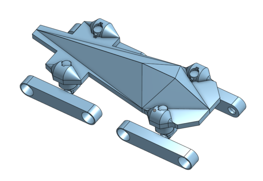
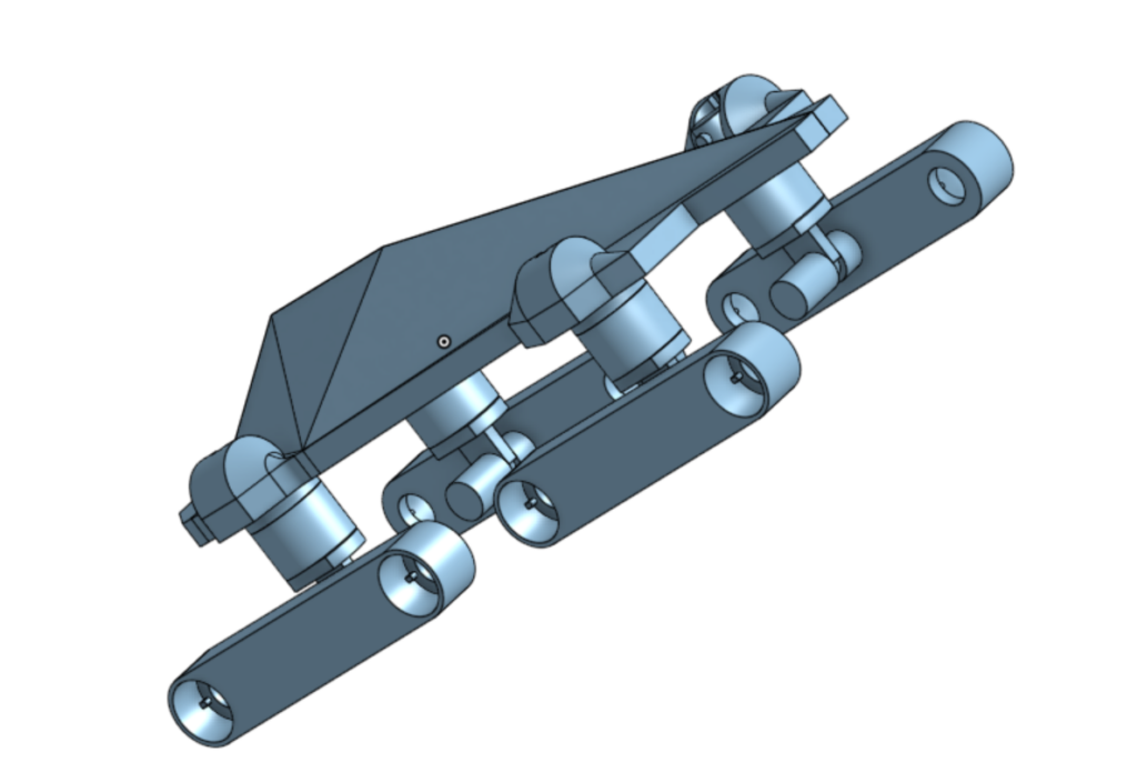
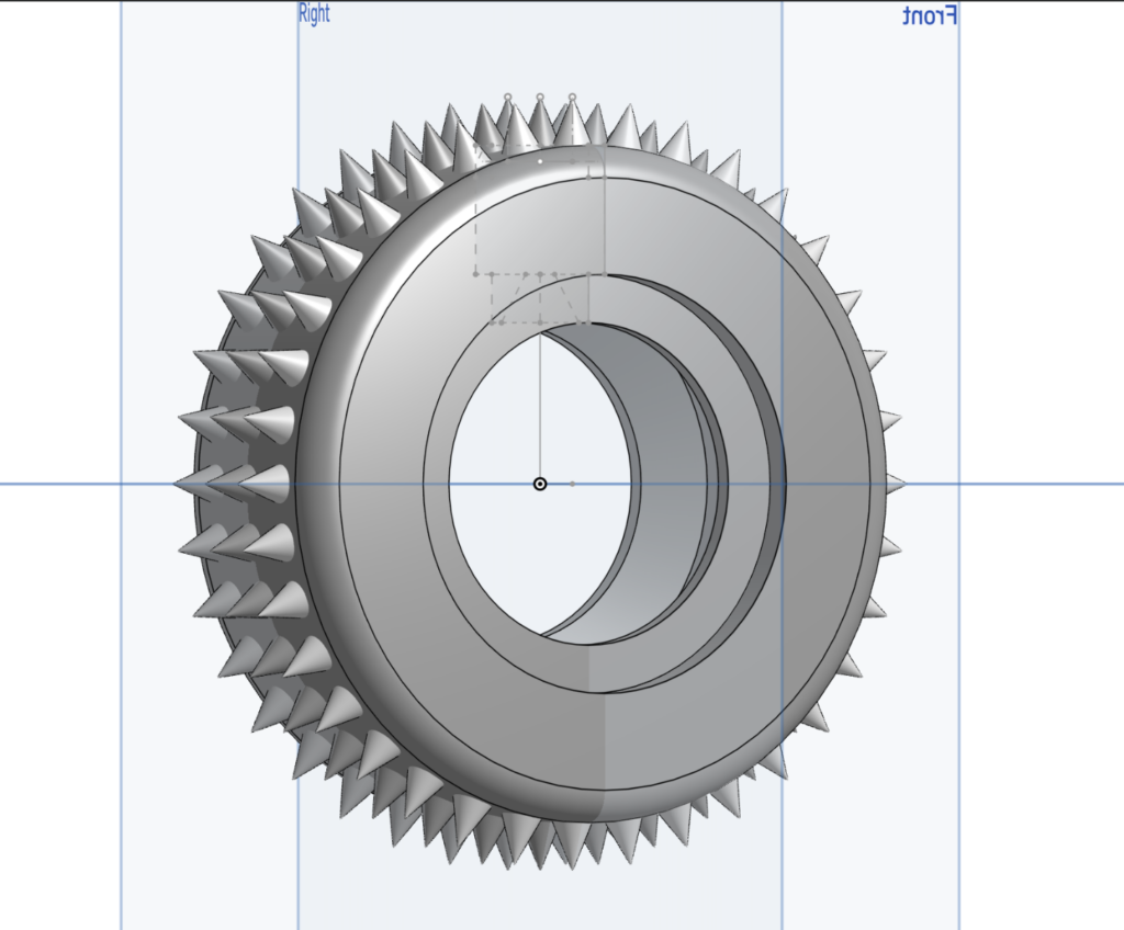
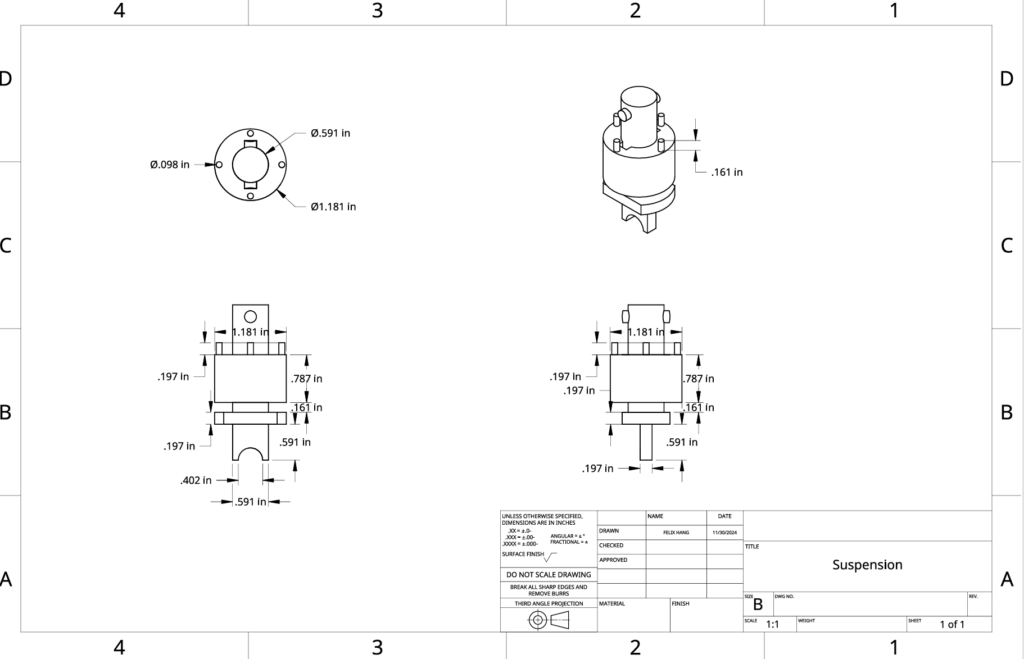
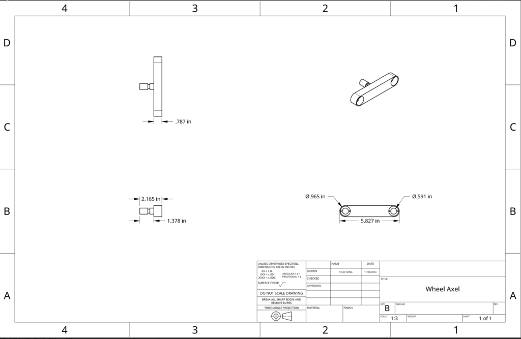
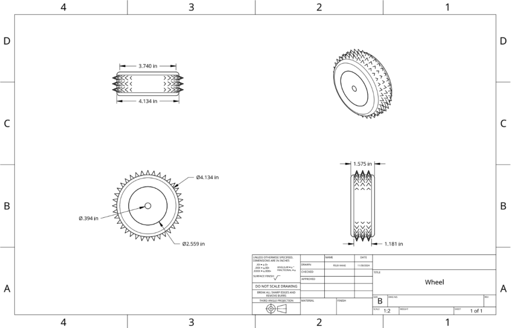
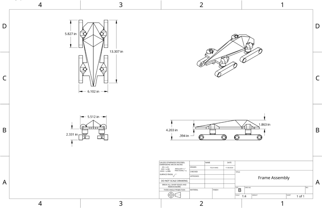
The vehicle has eight wheels, with each wheel having its own servo motor for power. These wheels are set up in pairs, and there are four groups of these pairs – two on each side of the vehicle. Every group sits on an axle that connects to a suspension system. This setup helps the vehicle to move better on the tough landscape on Enceladus. The axle has a central spring suspension. This allows it to adjust to bumpy surfaces by moving up or down as needed. A lock keeps the spring in place, which makes sure the vehicle stays stable and stops the axle from turning sideways when it shouldn’t. The wheels are made to handle rocky or uneven ground. Their tread takes inspiration from off-road tires, which gives them more grip on icy surfaces. The tires are made of soft material, which means more of the tire touches the ground. This softness also adds extra cushioning, which helps the vehicle stay stable and perform well on challenging terrain.
Vehicle Prototype Design
Here’s the full prototype design
Motor:


The arduino motor and code is what we would be using the run the wheels on our prototype. However, it does pose the question of how we would be able to fit the board and battery into our design. Furthermore, we would need to substitute the battery out with a solar panel instead.
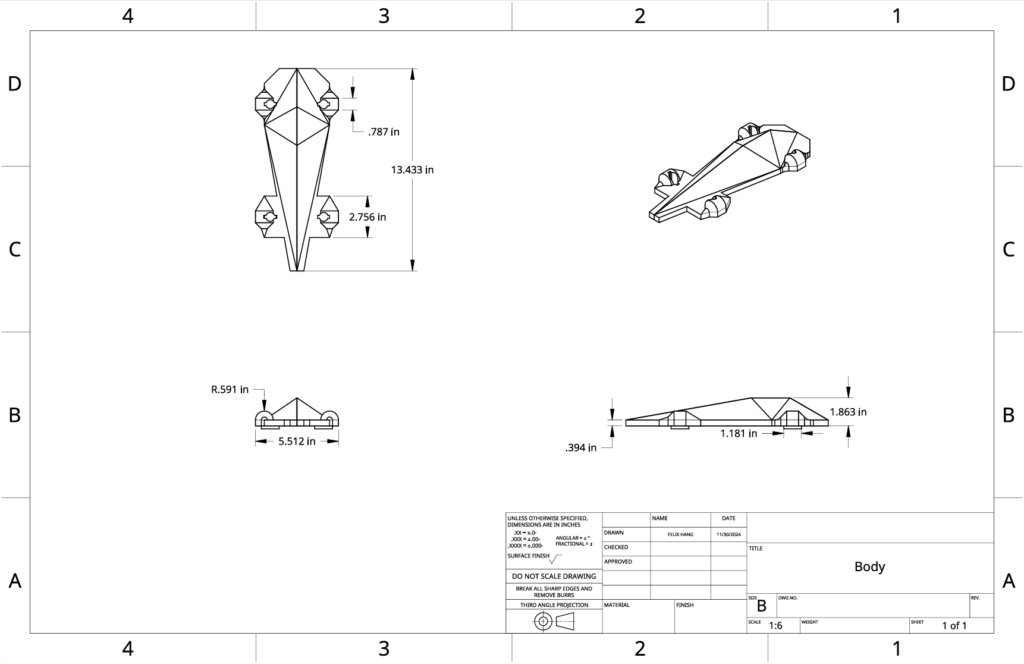
Mechanical Drawing
Body:
Suspension:
Wheels:
Full Assembly: The wheels will be printed and asembled outside of the rest of the parts.
Bill of Materials (BOM)

We chose aluminum for the materials because it’s most likely the only material that will be avaliable to us. A more desirable material would’ve been iron because Enceladus has low gravity which means we would probably need a heavier design.
Additionally, we require ad ons such as the motors and the solar panels to power the vehicle.
Testing Methodology
Testing the mobility
Objective: Test how well a vehicle’s suspension system handles uneven, slippery, and rugged terrain like Enceladus’s icy surface.
#1. Materials Needed
- Vehicle
- 3D printed prototype along with motors
- Simulated Surface:
- Large tray/Board for the testing area
- Aluminum foil/plastic wrap to mimic icy, slippery terrain
- Potentially add cooking oil
- Crumpled paper/rocks/blocks for the obstacles
- Sandpaper strips for the rough edges
- Measurement Tools:
- Stopwatch for timing vehicle performance.
- Smartphone for recording how the vehicle interacts with the environment.
#2. Procedure
- Setup the landscape:
- Create the terrain with the board and aluminum
- Add crumpled paper or rocks under the foil to create uneven surfaces
- Place other obstacles on top of the foil to simulate the landscape
- Test Runs:
- Run the vehicle through the course multiple times.
- Observe how the suspension responds to bumps, slopes, and obstacles.
- Record Observations:
- Measure the time it takes to complete the course.
- Note where the vehicle struggles -> can’t get over gaps/gets stuck
#3. Analysis
- Time to Completion: Faster times indicate smoother navigation.
- Obstacle Handling: Record and count how many times the vehicle gets stuck or tips over as well as where it gets stuck
Testing Energy Efficiency
Objective: Determine the energy efficiency of a solar-powered vehicle by measuring how well it performs on an obstacle course while using only solar-generated power.
#1. Materials Needed
- Light Source:
- A strong desk lamp, LED spotlight, or flashlight to simulate sunlight.
- Optional: Use multiple lamps to increase or vary light intensity.
- Terrain + vehicle
- Same as the mobility test
- Measurement Tools:
- Multimeter for measuring voltage and current generated by the solar panel.
- Additional payload
- Small weights to measure how that affects energy consumption.
#2. Procedure
- Set Up the Terrain:
- Reuse the same landscape as the mobility test
- Simulate light sources:
- Place lamp above the vehicle’s solar panels.
- Test the Vehicle:
- Place the vehicle at the start of the course and turn on the light source.
- Attach small weights simulate carrying different items.
- Repeat the course and compare performance.
#3. Data Collection
- Energy Generated:
- Measure the total energy generated during the run
- Example: If the panel produces 1.2 W and the vehicle runs for 5 minutes (300 seconds), total energy is 1.2×300=360 Joules1.2 \times 300 = 360 \, \text{Joules}1.2×300=360Joules.
- Distance Traveled:
- Measure the total distance the vehicle travels during the course.
- Energy Efficiency:
- Calculate energy efficiency by finding the input energy and work done
- Efficency % = (Work Done/ Input Energy) * 100
#4. Analysis
- Performance on different parts of Terrain:
- Observe if the vehicle consumes more energy on inclined or uneven surfaces.
- Identify parts of the course where the vehicle slows down or stops due to insufficient energy.
- Effect of Payload:
- Compare energy efficiency with and without the added weight.
- Effect of Light Intensity:
- Test at different light intensities using different heights of the lamp
- Identify the minimum light intensity required for the vehicle to move efficiently.
The two tests are centered around vehicle design. This works for us grade 10 students because all we need to focus on is fixing the prototype in CAD and not relying on expensive materials we won’t have access to. Factors such as temperature and cosmic radiation would be impossible to simulate in our classroom and workspace. However, this does mean that our tests are flawed in the aspect that we are assuming a lot of variables that we may not have control over. For example, our light intensity is much more intense compared to what it would be like on Enceladus. Further improvements and adjustments should probably be made to maximize efficiency.
AI was used in this blogpost – transcript
Leave a Reply