Introduction:
This assignment’s goal was to show my skills using CAD programs and learning to think through digital design programs. Proving my proficiency via these 5 skills:
Sketching – drawing a 2 dimensional representation of a face in CAD
Extruding – taking a sketch and turning it into a 3 dimensional object
Assembly – taking multiple 3 dimensional parts and sticking them together
Mechanical Drawings – converting your 3 dimensional parts and/or assembly into a 2 dimensional drawing
BOM – Creating a Bill of Materials – creating a list of all items required to fabricate an assembled object
To demonstrate these skills I have created a fictional fighter jet model that is intended to be 3D printed that consists of 4 separate parts that are assembled together in an assembly studio into one complete model. With a Mechanical drawing and Bill of Materials.
Sketching
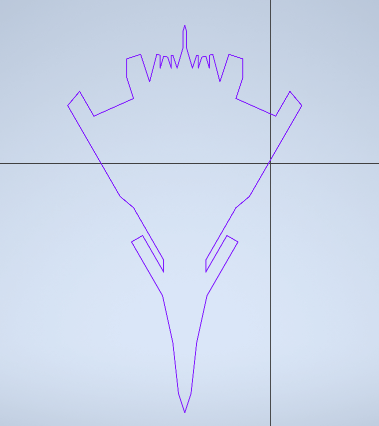
Fuselage + Wings

Cockpit+ Engine covers

Engines

I created a concept fighter jet based on real-life delta wing aircraft such as the Eurofighter Typhoon while drawing inspirations from cranked arrow wing jets such as the F-16XL as the base for my aircraft’s fuselage and wings. I have then continued to create 3 other “accessory parts” including a cockpit, engine covers, and actual engines on the bottom of the aircraft. I created the engines and main body in Autodesk Inventor Professional and the rest in Onshape. Assembling and Extruding everything in Onshape which bring me to the next part of the assignment Extruding.
Extruding
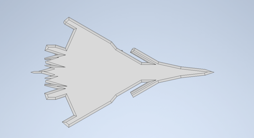
Main Body

Engines

Engine covers

Cockpit

Once I extruded all the sketched I’d created I began to smoothen some edges to give the model an appearance closer to one of a real fighter jet. However, I ran into some problems as I accidentally created a hole in one of the engines while I was fileting an edge. Which created unclosed boundary edges; an error that took me quite a bit of time to figure out. Once I have figured out the issues in my model and I was able to modify my parts into a size that I was happy with. This step took around 2 hrs to fix all the issues with my parts and to extrude my parts to the scale I was happy with. Which allows me to assemble my parts into the final product.
Assembly


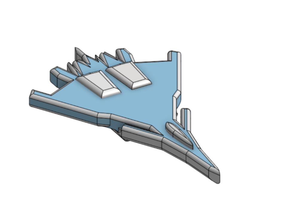
After assembling all the pieces that I extruded into the final product and I now have a single piece that I can use to create a mechanical drawing and accompanying Bill of materials for a possible machinist to create into a real product. I chose to place the parts like this and to add an appearance to the faces as I took inspiration from the Russian 5th generation fighter jet the SU-57. After finishing this assembly I then moved onto the last skill that I need to demonstrate; the creation of a mechanical drawing and BOM.
Mechanical Drawing and BOM

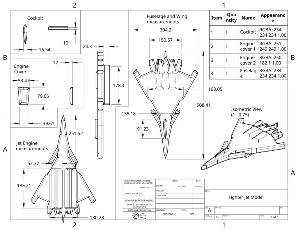
To show proof in the skill of Mechanical drawing and BOM creation I have added measurements needed to create a real model along with bill of materials that describes the parts and their colors. Along with an Isometric view and the scale ratio between the mechanical drawing and the intended product size being 1:0.75 respectively.
Concluding Thoughts
Overall, I think that this project was a really fun one. While I did have some problems during the middle it functioned as a pretty good learning opportunity and I feel that my skills and speed in CAD have definitely improved. And I’ve created something that I can be proud of and keep as a cool desk ornament while providing me skills that I can take to bigger and more complicated projects.

Leave a Reply