This year of Fusion has culminated to this final report and related project but before I talk about my final solution I first have to speak on my:
Project Goals
This project was planned to solve the inefficiency problems of electrically-powered performance cars.
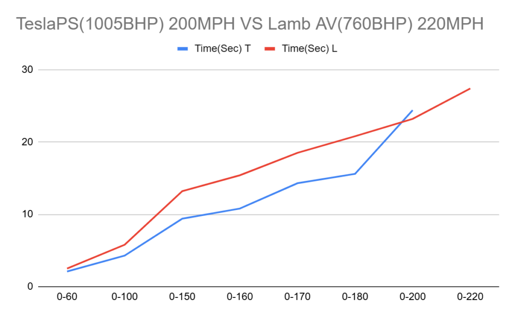
As seen in this graph the Tesla model S plaid, their fastest production car that produces 1005 BHP compared to the Lamborghini Aventador SVJ that only produces a BHP of 760. However, looking at this graph we can see that as speeds get higher and higher the Tesla starts to fall off and can’t even reach the same top speed as the Aventador. This phenomenon is due to one main factor; the gear ratio(s) in each car’s transmission, the Tesla only has one very high ratio that allows the car to have very quick acceleration however, once it’s speeds reach around 200mph the motor can’t spin the gears fast enough to allow the car the reach greater speeds thus bottlenecking the motor. This could be fixed using a traditional transmission design like the one in the Rimac concept 2; however, the power dynamics of an electric motor which provides power and torque instantly and spin constantly at a consistent top RPM, allows use to utilize a a CVT (continuously variable transmission) to it’s full potential as due to an electric motor’s tendency to stay at a consistent top speed we can gradually adjust gear ratios from high torque starting acceleration to lower torque top speed.
Project Constraints
My project’s users would be mainly electric car manufacturing companies such as Tesla or Rimac. However, a secondary user could be car modifying companies or passionate consumers that wish to upgrade their cars. The time frame of project was 2 months as I started this project mid March and would complete it half way through May. The main other constraint is costs as I can’t create a prototype to be actually installed on a car I don’t own. This involves not just testing but also fabrication materials, PLA instead of metal as it was more available to me as I used additive manufacturing.
Project Expectations
The scope of my project is quite small as my goal is to only create one working prototype as a proof of concept; additionally, my project is quite small physically only measuring 15 cm across and 25 cm long.
To identify success in my project I will use multiple factors; one being if it allows a motor to spin an axle or wheel at different RPMs without removing power to the motor.
Final Design
For my final design I have settled on a CAD design based on a planetary gear system.
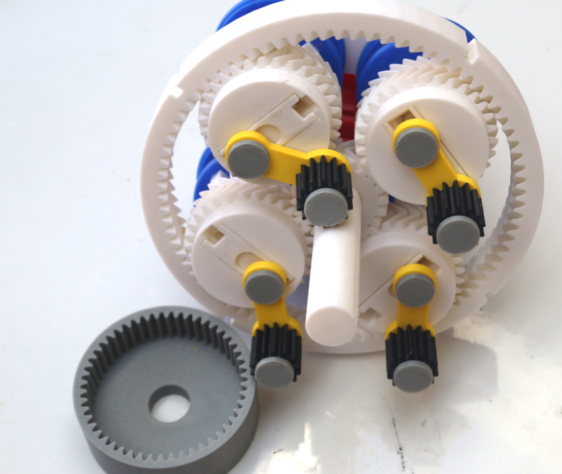
This design has 33 parts; the prototype as be made to self adjust with some simple small electrics; all that is needed is a RPM counter and a small high torque motor to adjust the gear ratios as needed. Below is a simple video that explains how the gear system works:
https://drive.google.com/file/d/1frvFAfGWsnz4t5mIUHamQV4owNv3nfX7/view?resourcekey
Project planning
To plan this project I first identified my problem: being that electric RC cars are inefficient but as that definition expanded through the aid and opinions of the UVic students I decided that I needed a new problem statement covering all performance electric vehicles. Thus this second version of my project was born, to start I worked on my CAD design on Autodesk Inventor a CAD platform that I was comfortable with. However, if you would want to modify this design in any way a CAD software that is moderately competent will provide the tools needed.
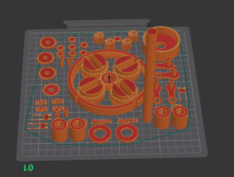
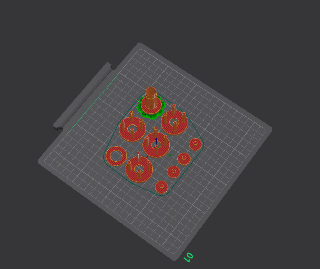
I then placed all the parts onto a 3D print slicer and printed them making sure to size parts that would fit into others smaller and vice versa. This allowed me to create a final prototype that required very little sanding and was quite smooth after aerosol lubricant was applied. Additionally, some gluing was required for which I used super glue.
Bill of materials
While I intended this project to be placed on an RC car I realized that due to the time constraints I wouldn’t be able to create a prototype small enough and durable enough to be placed on one. Thus the official requires BOM is as follows:
- CAD software (Autodesk, Onshape, etc)
- 3D printer & Software
- Filament (Ideally ABS)
Testing and Conclusions
Once I had assembled this very early stage prototype I tested it by spinning the input shaft in a full circle twice. Once with on the “low” setting and once on the “high” setting these settings were changed by adjusting the position of the output gear arms on each planet gear. The test footage is below:
https://drive.google.com/file/d/1JNgldKrHBRDxDkM28BzXdC-T4FF6wi_b/view?usp=sharing
https://drive.google.com/file/d/1ssRIrTJnHiNy6hzZ0DUYGTw0f1MXeZ08/view?usp=sharing
This test clearly shows the gear system can be adjusted to create a massive difference in gear ratios. Additionally, I can comment on the difference in torque as on the “high” setting the input shaft was much harder to spin than on the “low” setting. Overall, I think this project was a great way for me learn a large amount about a topic that has fascinated me ever since I was interested in cars being optimizing gear ratios. And while this project is quite focused in the space of engineering, ethics can always come into play. Whether it be if vehicles with this design were to be used by groups that commit crimes or even acts of terrorism or other unforeseen issues. However, this design can overall improve the performance of electric vehicles and could be looked into more thoroughly by a larger team with more resources at their disposal.
Refrences
Technical specs, dimensions, fuel consumption of cars. (n.d.). Ultimatespecs. https://www.ultimatespecs.com/
Leave a Reply