Abstract
The hover drone prototype is designed to test the feasibility of aerial mobility relevant to Titan-like conditions. Specifically, this prototype shall be used to evaluate a drone’s efficient lift-off, sustaining controlled flight, and making a 10 km round trip, bound to constraints similar to the low gravity and dense atmosphere of Titan. It shall also assess stability in simulated wind conditions and energy efficiency for longer distance travel.
Our test was designed to create an environment easily scalable to the 10 km test that we would need to complete on Titan under both ideal and realistic conditions. One being a straight-line path and the other being a zig-zag path simulating the mountainous conditions our vehicle would have to face on Titan. These tests look to provide a method for us to estimate performance on the moon.
Final Prototype
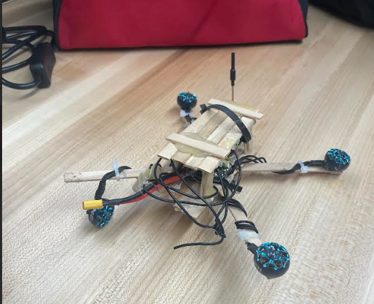
Our testing couldn’t be completed due to issues in production. We started with a plan to create a 3D model of the drone body and then 3D print it, constructing the drone over the winter break using purchased parts, and then testing in the new year. However, issues from construction confusion to overloading and exploding a capacitor occurred during this time—problems that can mainly be traced to our limited skills in soldering and circuitry.


I tried to fix the drone by myself and was successful in creating a drone that could turn on the motors and create enough downforce to hover for a split second. However, this was after we figured out that the 3D model we created was incorrect and the parts didn’t fit together. Thus, I created a backup frame out of popsicle sticks and hot glue. Despite some progress being made in the new year, we faced technical difficulties regarding code and motor setup. This caused certain motors to overcompensate when spun and led to a crash that ultimately destroyed the electronics on this drone. Due to this setback, we chose to pivot and scrap our original design and use a similar drone instead with a similar weight and parts. This was quite helpful as this drone was connected to drone goggles that allowed us to see the voltage per cell on demand.
Procedure
Materials:
- Small FPV drone (<250g)
- FPV goggles
- Measured flight path (110m)
- Drone controller
- 2 AA batteries
Preparation:
- Drone Setup:
- After gathering the materials read initial voltage per cell and record the value
- Find testing field
- We chose to use the length of the large Senior school rugby pitch (110m)
Test 1: Straight
- Use the drone controller to fly the drone along the flight path and back while maintaining a steady height and as straight as possible.
- Complete this test 3 times for more accurate information.
- Find initial and final voltage for each pass; record.
- Land.
Test 2: Maneuverable Flight Path
- Fly the drone in a consistent zig-zag path with the load of 2 AA batteries representing more realistic conditions.
- Fly with the same recording and testing structure.
Data Collection
For both tests we focused on measuring voltage per cell (V/PC) to decern efficiency.
- NL (No Load) Straight Flight: The drone was flown in a straight line without additional weight, simulating ideal conditions.
- L Zag (Loaded Zigzag) Flight: To better simulate real conditions on Titan, we taped on two extra 31g batteries to simulate the weight of passengers when scaled to the full vehicle and flew the drone in a zigzag pattern to replicate Titan’s conditions.
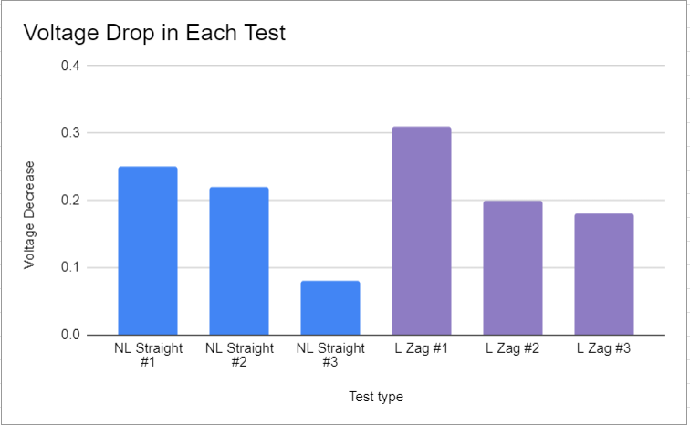
This table represents our recorded voltage per cell for each test:
| Test type | V/PC at start | V/PC at end | Voltage Decrease |
| NL Straight | 4.16 | 3.91 | 0.25 |
| NL Straight | 4.08 | 3.86 | 0.22 |
| NL Straight | 3.78 | 3.7 | 0.08 |
| L Zag | 3.91 | 3.6 | 0.31 |
| L Zag | 3.65 | 3.45 | 0.2 |
| L Zag | 3.55 | 3.37 | 0.18 |
While our prototype did not go as planned, these tests aligned quite well with our thoughts on performance and how it would work. Even though we changed a large amount of our procedure throughout the process and we used a vehicle not designed by us, we still gathered a large amount of helpful data. The only thing that we could have improved is having more control tests, such as a loaded straight or unloaded zig-zag. However, time constraints caused us not to test as much as we would have preferred.
Analysis
For these six tests, we recorded both the starting and ending voltage per cell for each round-trip. Our data shows that the battery voltage drop per cell decreases per consecutive test. This may be due to the fact that taking off requires a non-repeated amount of power that isn’t taken into account; it could also be because of the power regenerative properties of LiPo cells.

Finding Efficiency
In these tests, we define the efficiency of our drone by using voltage drop per cell per meter flown. We assume that the voltage difference represented by: (ΔV) is direct representation of the energy used by the drone thus the formula is:
D = Total meters
ΔV = Voltage per Cell
Test 1 Data:
- Test 1: 4.16 V−3.91 V=0.25
- Test 2: 4.08 V−3.86 V=0.22
- Test 3: 3.78 V−3.70 V=0.08
Avg: 0.1833 V
Test 2 Data:
- Test 1: 3.91 V−3.60 V=0.31
- Test 2: 3.65 V−3.45 V=0.20
- Test 3: 3.55 V−3.37 V=0.18
Avg: 0.23 V
Final Calculations
Using the total flight distance being 110m we can calculate the efficiency:
NL STRAIGHT:
L ZIGZAG:
This shows that the average Voltage consumed per meter was higher for the realistic conditions which matches with what we assumed. A truth most likely caused by the motor strain from the weight and maneuvering between turns.
Scaling to Titan
Titan’s environment quite different from our home on Earth; a fact that is quite helpful towards our vehicle design or any flying transport to be honest. With a gravity that is just 1/7th of Earths and a atmosphere that is 50% denser than Earth’s increase downward force and lift.
With these assists and factor we can adjust the voltage drop per meter to the ease of flying on Titan.
And the final Titan efficiency:
While this solution is based upon the assumption that the weight and power consumption ratios will stay the same as we scale up to the real vehicle. And this solution cannot be used a real benchmark we can still see that on Titan fight improves by a factor of 10.5x. Using this information we can conform that our design is at least somewhat efficient and effective for use on Titan.
Conclusion
The energy efficiency in V/PC per meter for our drone differs in a straight line and in a maneuverable zig-zag flight, as obtained from our tests and data analysis. Over a 110-meter flight in the NL straight flight test, the average voltage loss of the drone was about 0.1833 V, giving an efficiency of 0.001667 V/m. On the other hand, the zig-zag loaded test—the so-called L Zag—to which we added extra batteries, reached an efficiency of 0.002091 V/m with an average voltage drop of about 0.23 V. Also, the air density and lower gravity calculations that we designed would basically permit less energy consumption by 10.5x. If we analyze this, a more realistic route consumes about 25% more energy per meter when compared to the straight path.
While we had a large number of problems in this project, from CAD complications to difficulties with creating the drone, I think as the build leader of this project, I learned a large amount. I feel that if I were given this project again with all my newly gained experience, I could have made this drone project work. However, it was due to this inexperience paired with an overly ambitious project that caused our failure. While our communication during the winter break was shoddy, our combined efforts in the new year made considerable progress and allowed us to see this project hover for a split second before ultimately crashing.
While testing a drone that we created would have been more fun using our Robotics teacher’s drone for these tests still allowed us to collect data for this project and taught us a large amount about the design process and helped us learn from our mistakes.
Leave a Reply