Introduction:
- Decide what your device will do. Will it move something? Will it sense something and react to what it senses? Will it move itself? Don’t be too ambitious! The point of this is to demonstrate (or learn) skills, not to compete with Boston Dynamics (yet!).
2. Plan your device. What will it do? What components will you need? How will the components connect with each other?
3. Ensure that you can connect your computer to the Arduino board.
4. Program the Arduino to do what you need it to.
To demonstrate these skills I have created a Magic 8Ball using the Arduino platform.
Description of Robot
This robot will use the Arduino tilt sensor and LCD screen to detect tilting just like a real magic 8ball and depict its answer. To use the lcd screen one must attach a 220 ohm resistor and a potentiometer is needed to control the brightness of the screen. Along with other basic parts such as jumper wires the actual breadboard and Arduino Uno board.
Here is the total list:
- 1 LCD screen
- 1 Tilt Switch
- 1 10k-ohm (or 10kΩ) Resistor with the following coloured bands: brown, black, orange, gold
- 1 220-ohm (or 220 Ω) Resistor with the following coloured bands: red, red, brown, gold
- 1 Potentiometer
- A large amount of jumper wires
Construction

Credit: https://uviclibraries.github.io/arduino/virtual_workshop_children/lucky_8-ball.html
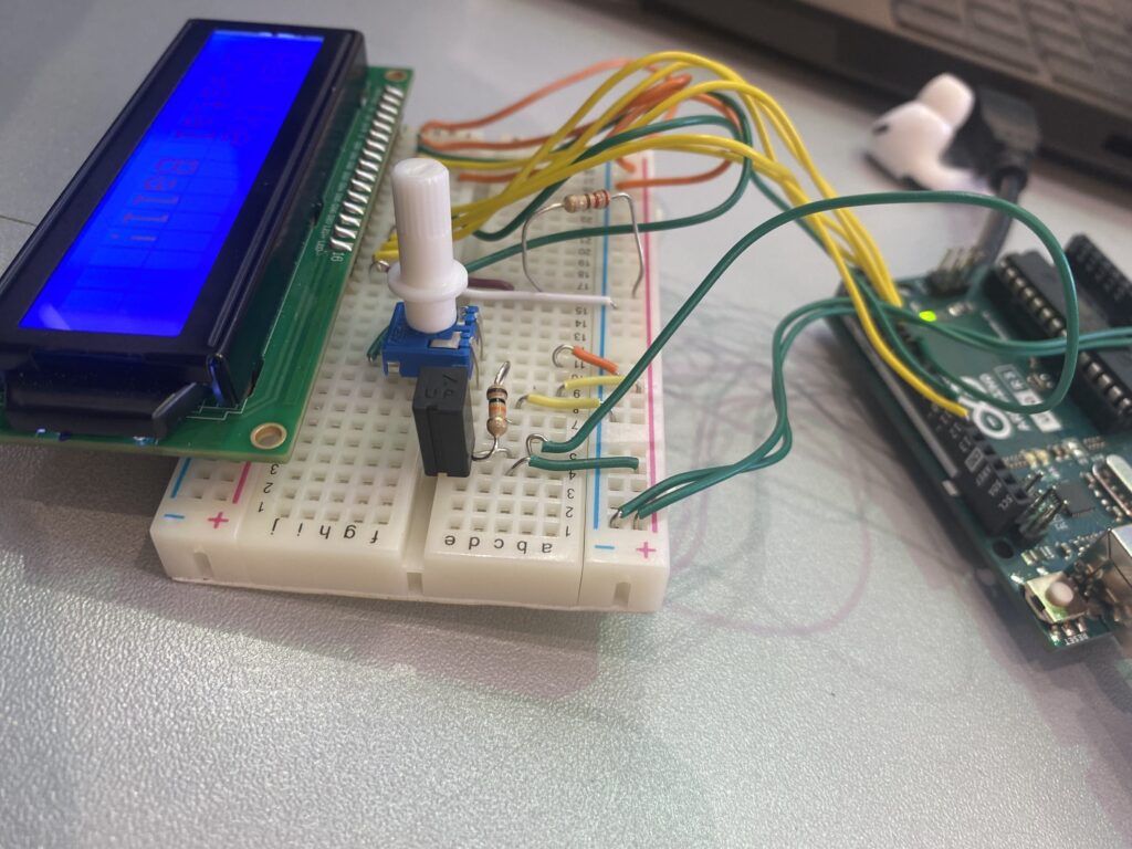
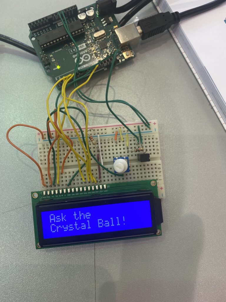
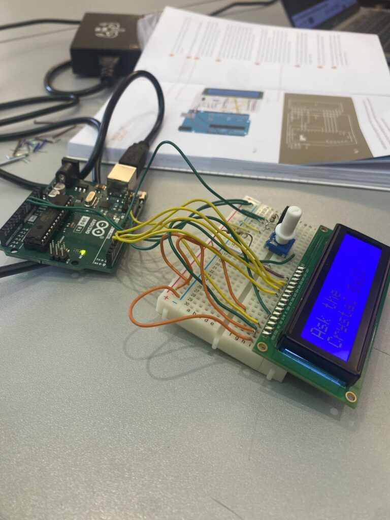
Making this robot somewhat hard as a large amount of wiring is needed and getting just one wire incorrect will make it so that the screen either doesn’t turn on or it will depict a bunch of nonsense. My pictures aren’t the exact same as the picture above but the idea is the same.


Code Explaination
#include <LiquidCrystal.h>
LiquidCrystal lcd(12,11,5,4,3,2);
const int switchPin = 6;
int switchState = 0;
int prevSwitchState = 0;
int reply;

void setup(){
    pinMode(switchPin, INPUT);
    lcd.begin(16, 2);
    lcd.print("Ask the ");
    lcd.setCursor(0, 1);
    lcd.print("Crystal Ball!");
}

void loop(){
    switchState = digitalRead(switchPin);
    if(switchState != prevSwitchState){
        if(switchState == LOW){
            reply = random(8); //pick a number from 0 to 7
            lcd.clear();
            lcd.setCursor(0, 0);
            lcd.print("The ball says: ");
            lcd.setCursor(0,1 );
            switch(reply){
                case 0: lcd.print("Yes");
                break;
                case 1: lcd.print("Most likely");
                break;
                case 2: lcd.print("Certainly");
                break;
                case 3: lcd.print("Outlook good");
                break;
                case 4: lcd.print("Unsure");
                break;
                case 5: lcd.print("Ask again");
                break;
                case 6: lcd.print("Doubtful");
                break;
                case 7: lcd.print("No");
                break;
            } //end of switch
        } //end of nested if()
    } //end of outer if()
    //update the tilt switch status
    prevSwitchState = switchState;
} //end of loop()
The code used for this robot isn’t too much and it isn’t too hard to understand. But an explanation for this code is as follows:
The first couple lines identifies the ports that the LCD and tilt switch are plugged into. The lines below set what the screen says when the program starts. And all the lines below that generate a random number and that number is tied to message that is displayed onto the screen when the tilt sensor is triggered. And that’s pretty much it a pretty simple code line for a really cool robot.
Final Product and Conclusion
In conclusion, this project was probably the hardest that I had to tackle as I had the least amount of experience in Arduino compared to CAD and Coding. And as you can see components are a bit loose causing the tilt sensor to sometimes not trigger which is why you see me holding down the tilt sensor and potentiometer. Overall this project is really cool and helped me learn a lot about robotics. And if you can get your hands on the components I recommend you try this project out.
Leave a Reply