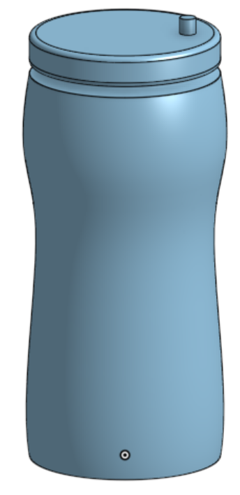
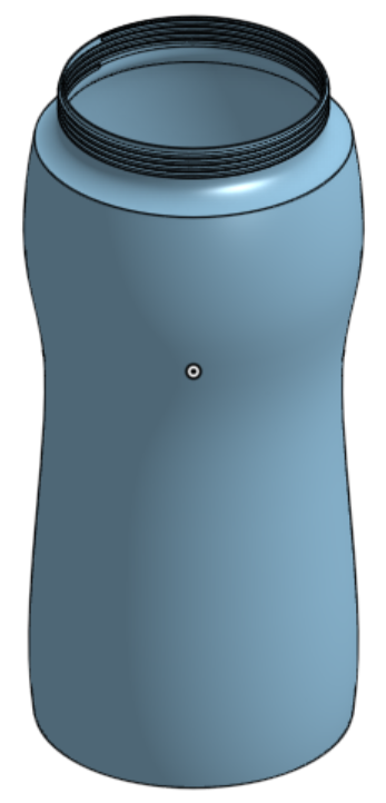
In this Fusion assignment I was assigned to do something not that complicated in CAD. I decided to do a water bottle brcause it was really easy and can show a decent amount of basic skill in CAD.
Sketching
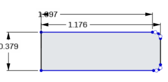
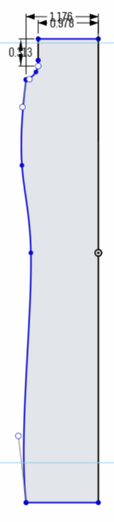
The first step was to do a sketch of the bottle. The bottle is in two parts, the first part is the actual bottle and the second bart is the lid. I made a sketch of half of it not really regarding the sizes.
Extruding
Then I use the revolve tool to make the bottle shape. After that I had to worry about making a way the lit and bottle can fit together. So I started by using the helix tool and make a new sketch then use the sweep tool to create screw like teeths on the bottle.
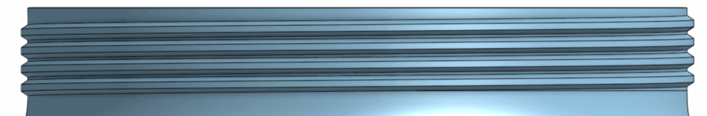
I did the same on the Lid but with the sweep I made it remove so it can perfectly fit onto the bottle. after making a hole that is the right size. in the cap I used a sketch and used the center point circle tool to make a circle then used the extrude tool to remove a hole through the original design.
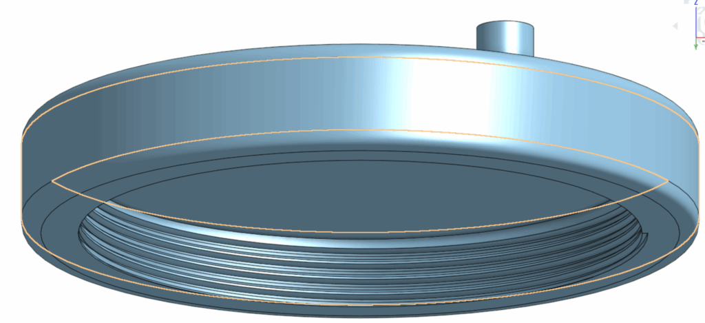
For the cap you may have noticed a small cylinder on top of it, it was mainly used as a point to recognize if I did my assembly right in the future.
After these steps I still had to make a hole in the bottle. This time differently I used the shell tool because it was easy and also because the irregular shape of the bottle.
Assembly
The Last step was to do the assembling. First I created a fastened mate on the bottle to the origin point. After that I put a cylindrical mate on the cap to the bottle. Last I made used the screw motion tool to make the Lid act like a screw so it can go on the bottle as I designed it to. Now to explain why the cylinder on top of the Lid is added, the reason for that is because it is easy to see if the screw motion actually works because it it really hard to tell if the Lid is rotating in a circular motion without adding anything.
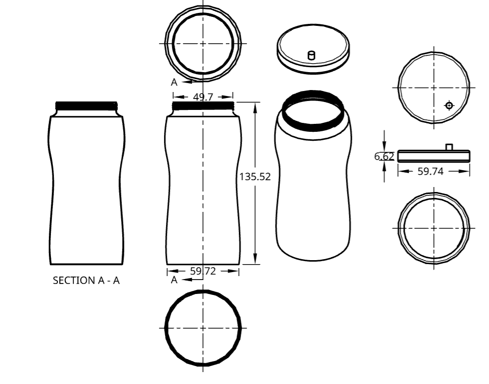
Mechanical drawing
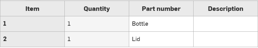
BOM
AI usage
AI was not used at any point in this assignment
Link to Project
Leave a Reply