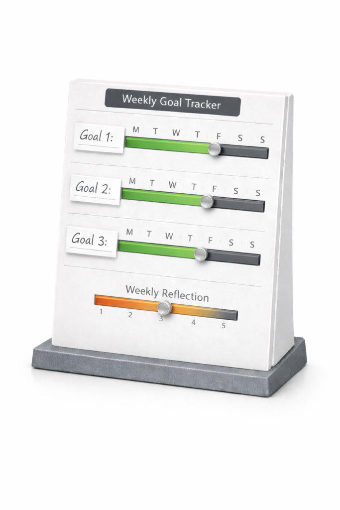
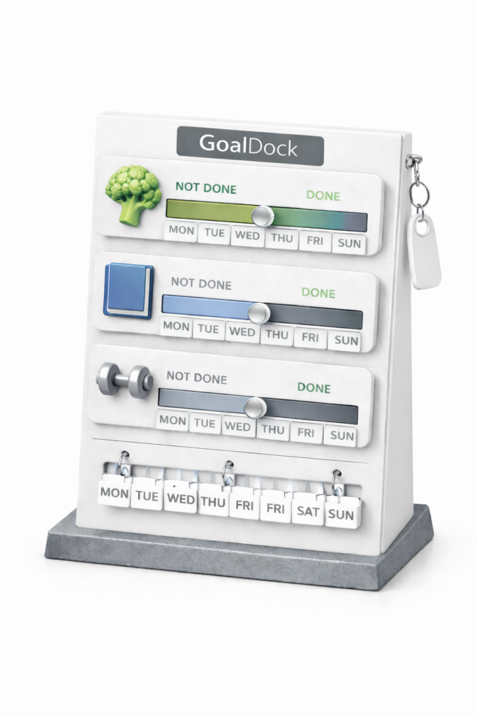
So after my first idea of the “Goal Dock,” I kind of did more thinking. I know that I would want to create something meaningful and that I could hopefully work on later, so I went deeper into thinking about the idea, and the more I think about it, the more I feel like this idea would not be that great.
The reason why I have tried to create a physical product is that I don’t have much experience in coding and app development, and I was worried that I would not be able to code a fully functional app.
After I had a conversation with Mr. Crompton, I found out that I am able to use the help of AI in creating my app as long as I am still the one with the ideas and the execution plans. The AI is simply going to be a tool that can help me show my ideas in a visual form.
With that in mind, I started to look at different digital options. I then settled on the idea of making an app that can help users, especially students, to create meaningful and structured goals and help them keep track of their progress interactively and interestingly.
The Problem:
Students have meaningful goals, but they often struggle to turn them into manageable steps and daily actions that they can take.
My main audience is students, since they have lots of things to do each day and often struggle with keeping up with their goals.
I personally experience this problem. Sometimes I am just overwhelmed with assignments that I overlook the importance of simple daily actions that could help me work towards my goal.
Research
For the framework to be effective, I looked at a few research studies to justify why I have chosen to do my system (which will be explained later) the way that I am doing it.
- Goal Setting Theory – Edwin Locke and Gary Latham
- This research suggests that people perform better when goals are specific, challenging, and paired with feedback. Goals are also more achievable when paired with steps that give people direction
- Link for more info: https://opentext.wsu.edu/theoreticalmodelsforteachingandresearch/chapter/goal-setting-theory/
- Self-efficacy – Bandura
- People are more likely to act, persist, and recover from setbacks when they believe they are capable of succeeding. Small wins could help people overcome setbacks and gain the confidence to continue
- Link for more info: https://www.simplypsychology.org/self-efficacy.html
- Implementation Intentions – Gollwitzer
- When people turn goals into concrete, action plans, actionable plans, they are more likely to follow through with the goal
- Link for more info: https://en.wikipedia.org/wiki/Implementation_intention
- Progress Monitoring – Harkin et al.
- This analysis showed that when people keep track of their progress, they can better achieve their goals
- Link for more info: https://pubmed.ncbi.nlm.nih.gov/26479070/
- Habit Formation – Lally et al.
- This finding shows that habit builds on consistency and repeated actions.
- Link for more info: https://psycnet.apa.org/record/2010-22273-010
- Atomic Habits – James Clear
- Instead of focusing on bug goals, we could focus on small habits that can be repeated every day. Thu, we need to focus on the system of achieving the goal.
- Link for more info: https://jamesclear.com/atomic-habits-summary
Introducing Pebble
Pebble is a student-focused personal development tool that could help students turn their goals into actionable plans while keeping the student on track with their progress.
Although the personal development app market is saturated, Pebble is able to distinguish itself from the pack by offering users a simple, interactive, and gamified experience, similar to that of Duolingo.
Pebble uses AI integration and a structured flow to help the student stay on track with their goals.
This is the goal-setting process for Pebble:
Goal – The app asks the user for their goal
↓
Why it matters – The app forces the user to explain why this goal is important to them
↓
Make it more specific – The app helps the user to further explain their goal by using AI suggestions that the user can modify
↓
Break it into steps – The app then asks the user to break their goals into actionable steps
↓
Choose one active step – The app then tells the user to focus on one step, and the user calculates in advance the amount of time they might need to complete the step
↓
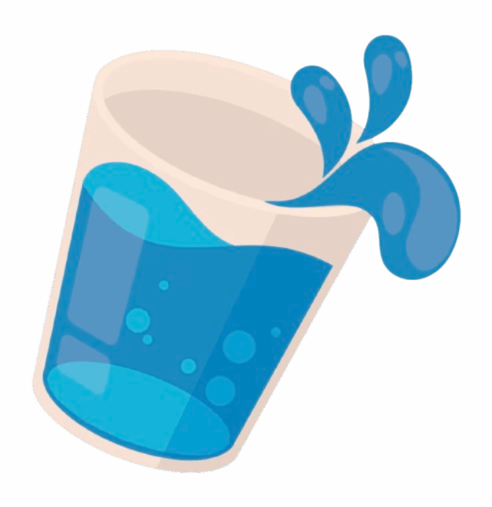
Plan actions – Then the app will use AI suggestions to help the user break the step into possible actions. These actions could be repeated actions for everyday such as drinking 2 bottles of water every day, or they could be day-specific actions like completing a mock test. The time at which the user inputs the action is also flexible; the user could add an action or remove one anytime they want, based on their personal needs (some users might like to plan ahead of time, while some users like to go day by day)
↓
Record progress – Pebble has an interesting way of recording progress and motivating the users, which will be explained later in the blog.
↓
After all the steps of the goal are complete, the user has completed their goal, and if this is not the case, the user can simply add another step and keep on working.
↓
Earn rewards: the user is able to earn rewards when they complete different stages of the goals, which will be explained later.
↓
See the full journey – The user will also have a way to view their entire journey with the app and the progression of their goals over time.
Recording Progress:
The progress recording of Pebble is quite interesting.
The user sets up actions that they will take in advance in the app, and then when he/she completes the action, they can mark it as finished on the app, and the app takes the action and stores it in the action catalog that can then be used to monitor progress and allow the user to reflect when they need it.
The user also has the option to input how much time they have devoted to the goal on that day. This will allow the user to see their own efforts on a chart regarding how much time they have spent on the goal.
After each day, the user can rate themselves on a scale of 5 of their own effort, which adds a level of self-assessment into the equation and encourages reflection.
To track the process of the entire goal, I settled on a timeline method. Instead of the conventional calendar view, I used a timeline. The timeline allows the user to have an idea of the journye of the goal. This timeline includes events like when the goal was created and when one step was achieved.
Now lets look at how exactly the actions, steps, and goals work.
After the user has chosen a step and planned out actions, they are now ready to work towards them. After many actions and days working towards the step, the user completes the step and moves on to the next step.
The time in between the start of the step and the end of the step could sometimes be long, and the user would need some type of encouragement. This is where our mascot, Pebble, comes into play.
Pebble is a penguin that is similar to the owl in Duolingo. I can pop up on the user’s screen and give them doses of encouragement from time to time.
After the completion of a step, the user earns a flame. The flames are cartoon-like and have different colors for different goals, since the user might be working towards multiple goals at a time. The flame will also be labeled with the name of the step.
After the completion of each step, the app will provide the user with a celebration moment where the user can feel good about their accomplishment, and they are also able to view all actions and time and all other associated information about this step in an achievement page where all the falmes are stored in little jars.
After all the steps are completed in a goal, all the flames will merge into a gem that has the corresponding color of the flame and will also have the name of the goal on it.
The gem will then have all the information for all of the steps and thus all actions involved in achieving the goal. It will also contain the amount of time and days that you have worked on the goal.
The user is always able to go to the achievement section and look at all their goals and reflect on them.
Current Progress:
Currently, I think I have pretty much finished with the design of the idea. Maybe a few fine-tuning is needed, but the general direction is basically laid down.
One thing that I am kind of worried about is the fact that while it sounds like a pretty interesting idea, I am not sure if this idea will be able to find success if I develop it further and maybe launch it into the market, perhaps.
I would like this project to be able to be something that I am able to develop further outside of Fusion, since I am considering pursuing some entrepreneurship opportunities. Thus, I really have to have a well-grounded idea in order for my time not to go to waste.
Possible Challenges:
Since I am competing in a pretty saturated market, I do have to have something that can really attract people to use my app over the others. I do believe that I do have some interesting perspectives to offer, and I may just need some more time to fine-tune the idea and really figure out my differentiating strategy.
Another challenge could be the fact that I haven’t used any AI to help me code before, so I might be stuck on a few concepts. I am planning to combat that by spending some time during the break to learn more about tools like Claude that can aid me in my creation process.
What Now?
I think I would still stick with this idea for now, but if I have any better ideas, I might do another pivot. However, since I already had some good thinking with this product, I might be able to use some of the thinking to apply to the next idea, so that the thinking I did now will not go to waste.
The Use of AI
I did use AI to help me brainstorm ideas and rate my ideas. I will also use AI later to help me create a visual representation of my app, since I lack the knowledge of creating apps.
Transcript: https://docs.google.com/document/d/1Inko9AxDcn6xnCmx3SGC4OTkxNQfUTs–ljifJ5ECVw/edit?usp=sharing