
Vehicle designed for Trappist 1-e

Definition Statement:
Our mission is to build a vehicle that can:
- withstand Trappist-1e’s extreme contrasting temperatures
- traverse the uneven and rocky terrain
- and endure the immense radiation emitted by Trappist-1e’s star
Additionally, the vehicle must be large enough to hold at least four individuals and have sufficient energy to travel 10km.

The Problem:
We need a vehicle that can travel on the planet Trappist 1-e
Trappist 1-e had a rocky and dusty surface, similar to that of Earth

Brainstorming:
We brainstormed a few versions to arrive at our final design:
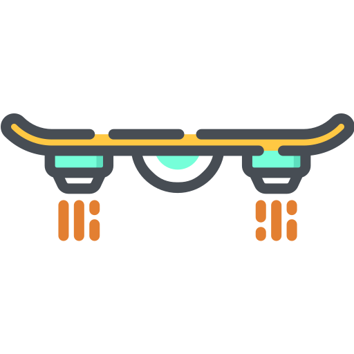
- The Hover Board System: We thought of an idea to attach a hover board underneath the vehicle so it can float on top of the rocks and uneven terrain
- We figured this concept would be hard to create and, at the same time, energy-inefficient.
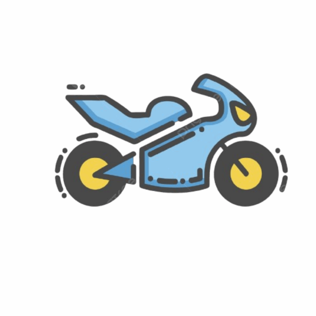
2. The Motorcycle: The second idea we had was a motorcycle with a solid outer shell. It would be easy to turn and would be fast.
- We realized the design was flawed because the vehicle’s 2 wheels could be imbalanced and unable to support the weight of our entire crew and equipment.
3. The Rocker-Bogie System (what we settled on): The third idea was the rocker-bogie system, similar to those used in Mars vehicles. It consists of two arms that work together to climb uneven surfaces.
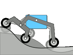
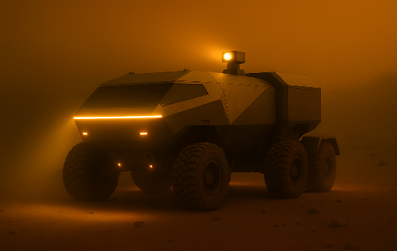
- Visual Representation of the vehicle (created by AI)
Role of the Test:
The test we performed was crucial for evaluating whether our vehicle can operate under conditions similar to those on Trappist-1e. We were able to see the vehicle in operation rather than viewing it virtually in platforms like Tinkercad.
The primary goal of the test is to measure the energy efficiency and mobility. By testing the vehicle on both a dust-and-gravel surface and a smooth surface, we compared how terrain roughness affects current draw, energy consumption, and overall efficiency. The smooth surface served as the control condition, while the gravel tests simulated the rocky terrain present on Trappist-1e.
Through testing, we aim to understand how the rocker bogie system improves our stability and traction on the ground. We also hope to understand the difference in the energy required for the vehicle to travel on rough and smooth surfaces.

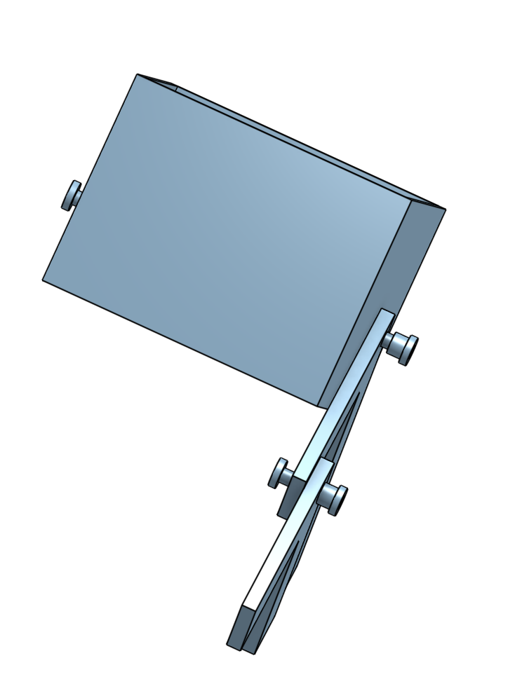
The Method and the Procedure: The Rocker-Bogie System
We finally settled on the rocker-bogie suspension system, a suspension system used on Mars rovers. It includes 3 main parts on each side of the vehicle:
- A rocker arm ( the long arm)
- A bogie arm ( the short arm)
- 3 wheels per side (2 connected to the short arm and 1 connected to the long arm)
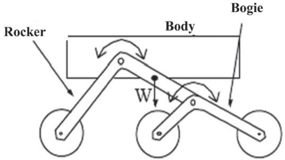
- Above is a simple diagram of a rocker-bogie system
The Benefits of the Rocker Bogie System:
- Improves traction
- Reduces wheel slip
- Makes energy use more efficient on uneven terrain
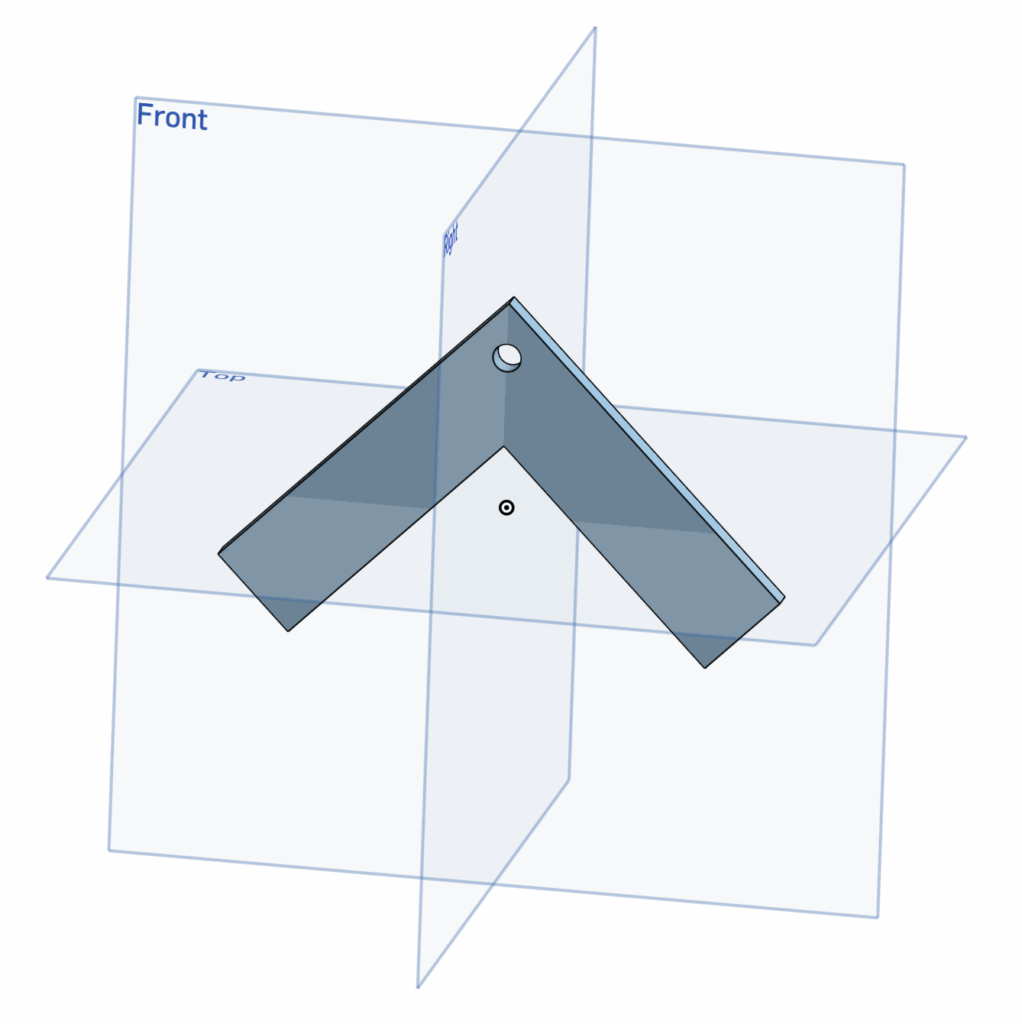
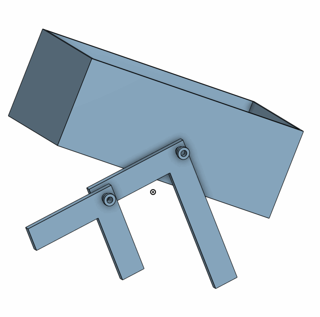
The Rocker Arm (the long arm)
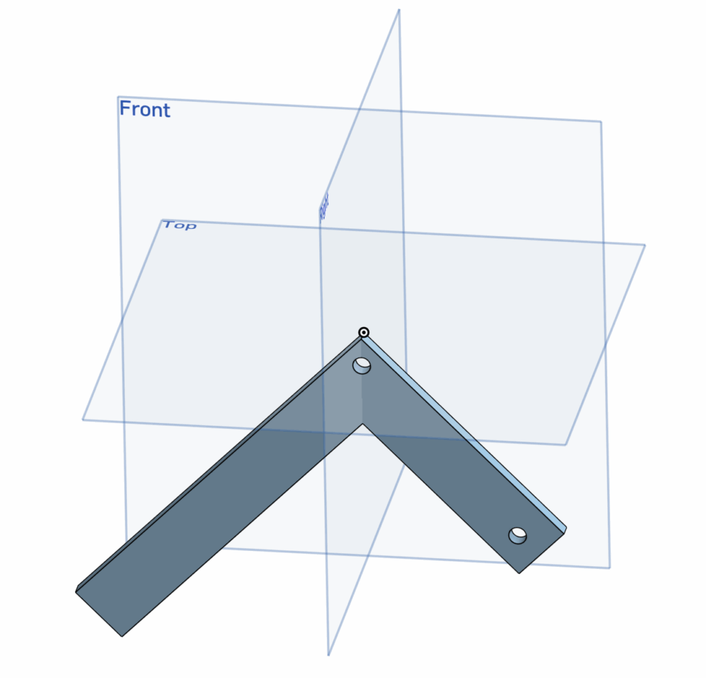
- The rocker arm is the main structural component of the rocker-bogie system.
- It connects the front wheel to the chassis (the body) and allows the wheel to rotate upward when encountering obstacles.
- This movement helps keep the rover stable and ensures continuous contact between the wheels and the ground.
The Bogie Arm (the short arm)
- The bogie arm is the shorter component of the rocker-bogie suspension system and connects the middle and rear wheels on each side of the rover.
- It is hinged to the rocker arm, allowing the two rear wheels to move independently when travelling over uneven terrain.
- This design helps distribute the rover’s weight more evenly and reduces the chance of wheel lift or loss of traction.
The Chassis (the body)
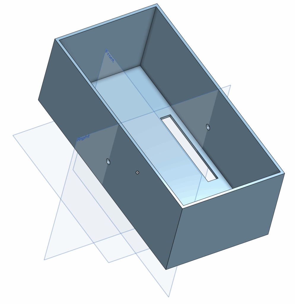
- This is the body of the rover
- Includes mounting points for the rocker arm
- The cutout in the middle of the body is designed so that the wires from the TT motors can connect to the breadboard.
Screw Head
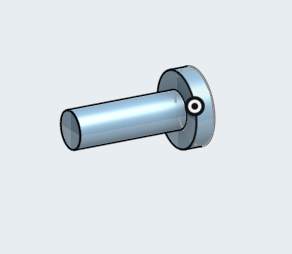
- This screw head attaches to the screw base and serves as a pivot point for the connection points between the chassis and the rocker arm, and between the rocker arm and the bogie arm.
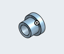
Screw Base
Screw Assembly
- This demonstrates how the screw head and screw base can connect components.
Connecting the Chassis to the Rocker
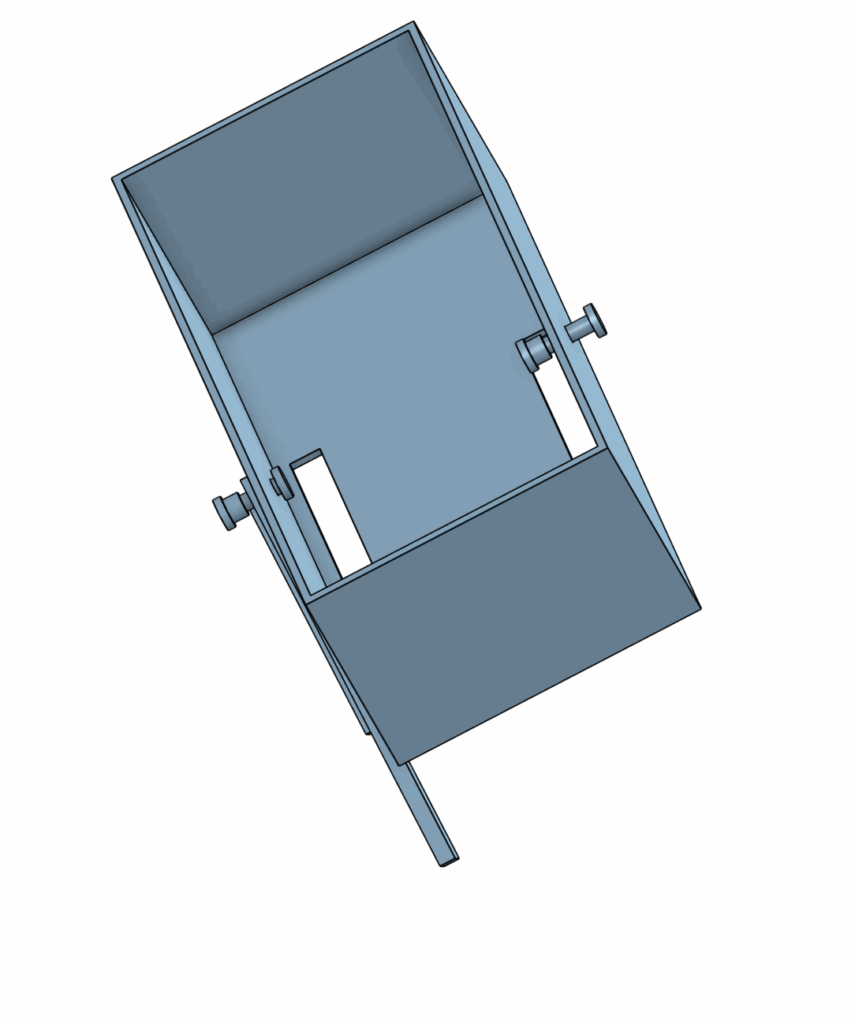
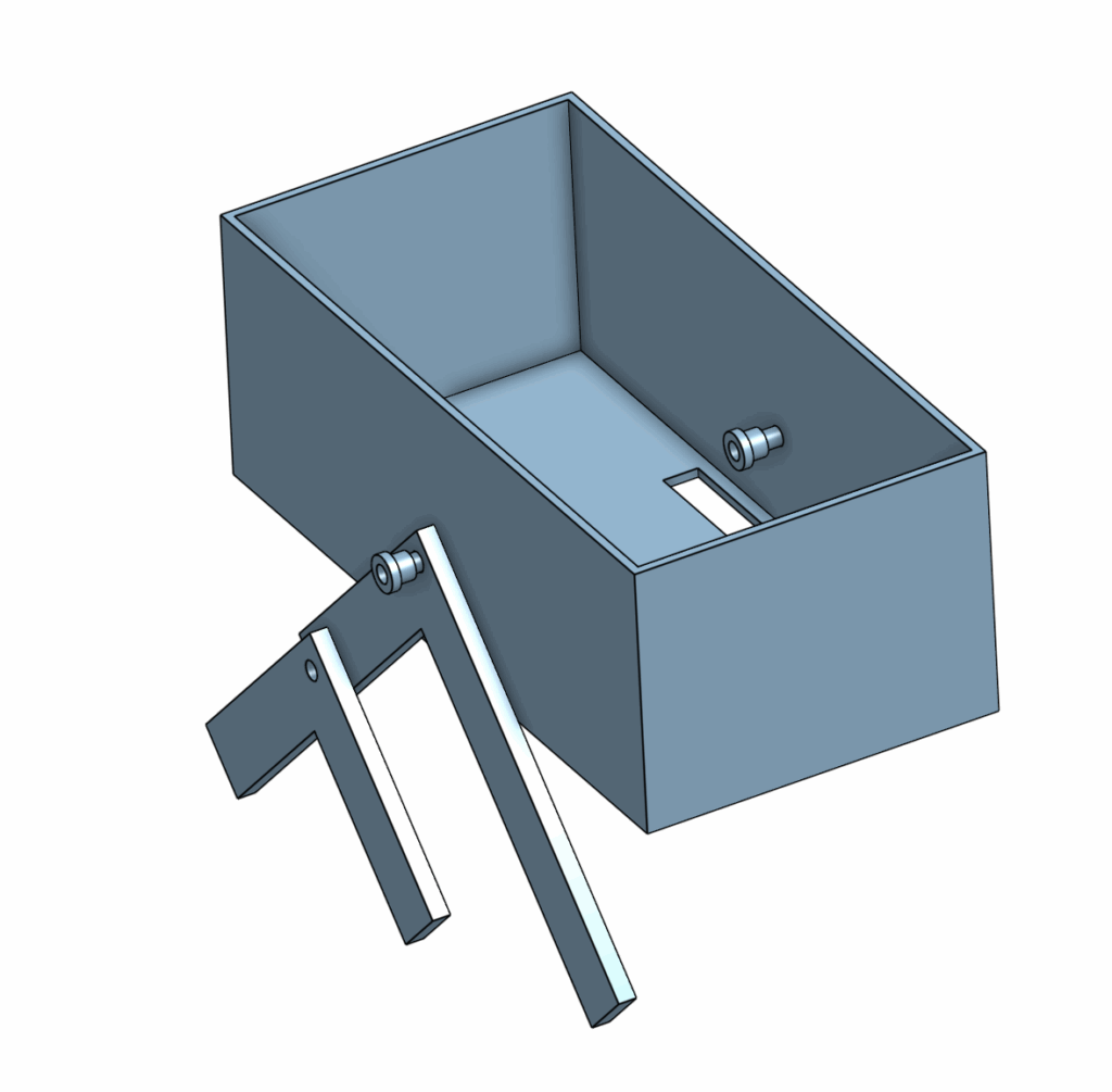
- We use the screw in order to attach the rocker arm to the chassis, and in order to attach the rocker arm to the bogie arm
Mechanical Drawing
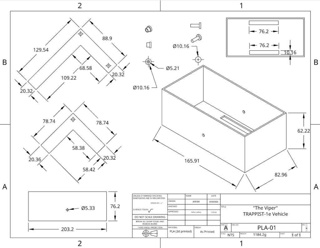
- This is the mechanical drawing of all vehicle components.
- The screw head and screw base each have 3 drawings from different angles.
- The chassis has 3 different drawings showing it from different angles.
- All measurements are in millimetres (mm)
TinkerCAD:
Video of design in motion:

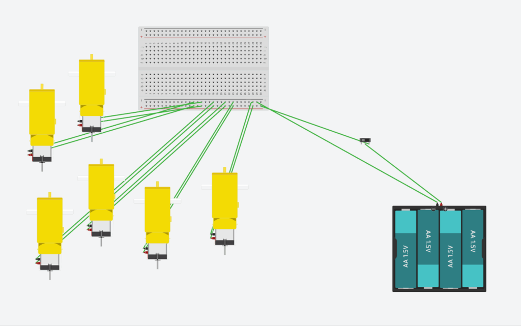
- We used TinkerCAD to simulate the network and circuit of the vehicle
- We used 6 TT motors (3 on each side of the vehicle)
- 1 breadboard
- 4 AA batteries
- A push button
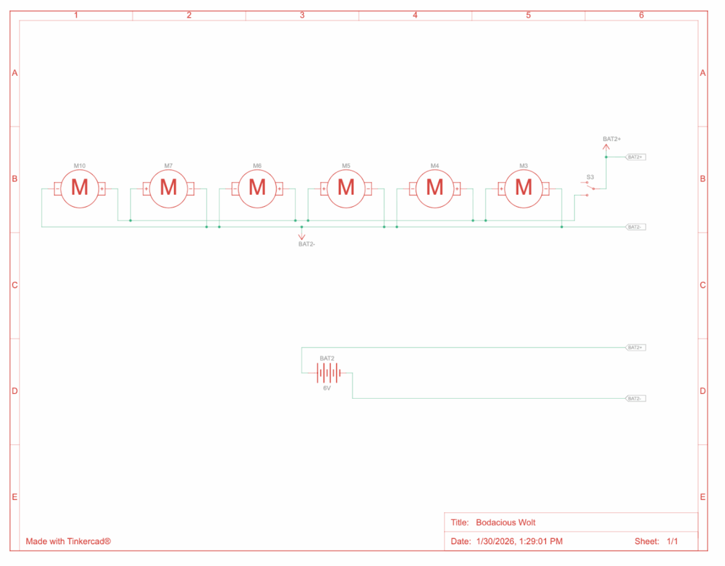
- Above is the circuit diagram for our vehicle
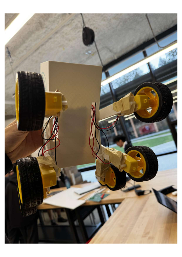
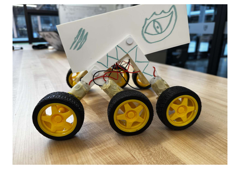
Prototype Photos:
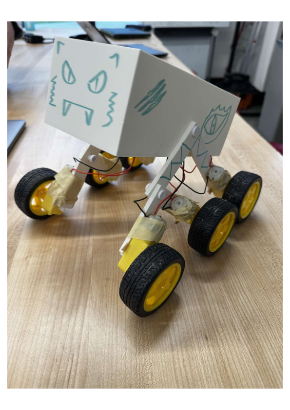
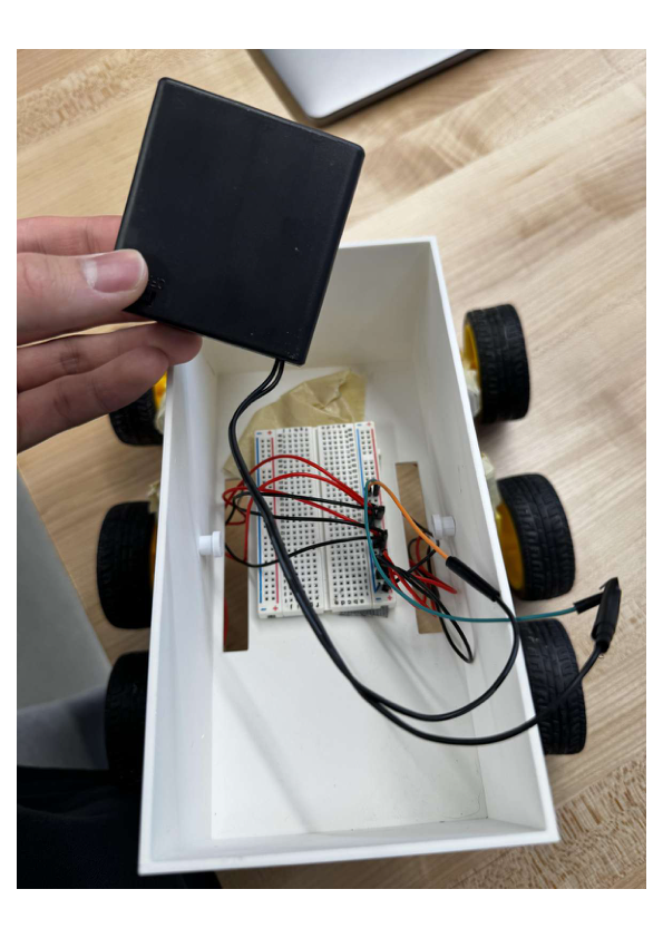
- The black box holds 4 AA batteries and contains a button to turn the vehicle on and off
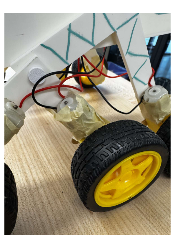
- TT motors are attached to the wheel, the rocker, and the bogie arms.
- We used a combination of Gorilla Glue, Super Glue, and tape to strengthen the connection between the motors and the arms.
- Cutout on the bottom of the vehicle for the wires from the motors to connect to the breadboard.

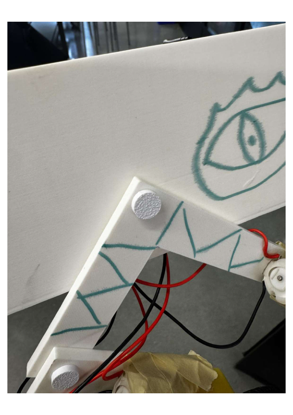
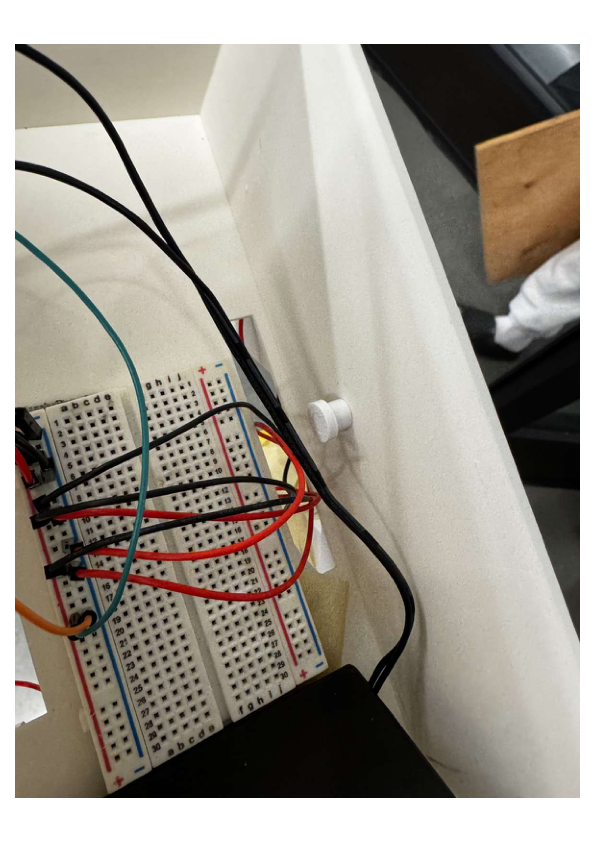
- Screws are used to connect the rocker arms to the chassis.
Vehicle Tests:

The tests actually went pretty smoothly:
Test 1: Gravel surface

- Temperature: 3 °C
- Distance travelled: 106 inches = 2.692 m
- Time: 11.5 s
- Mass of rover: 1184.2 g = 1.184 kg
Electrical Measurements:

- Because the vehicle did not maintain a steady voltage during the test, we calculated an average voltage from the pre- and post-test readings.
Current Measurements:
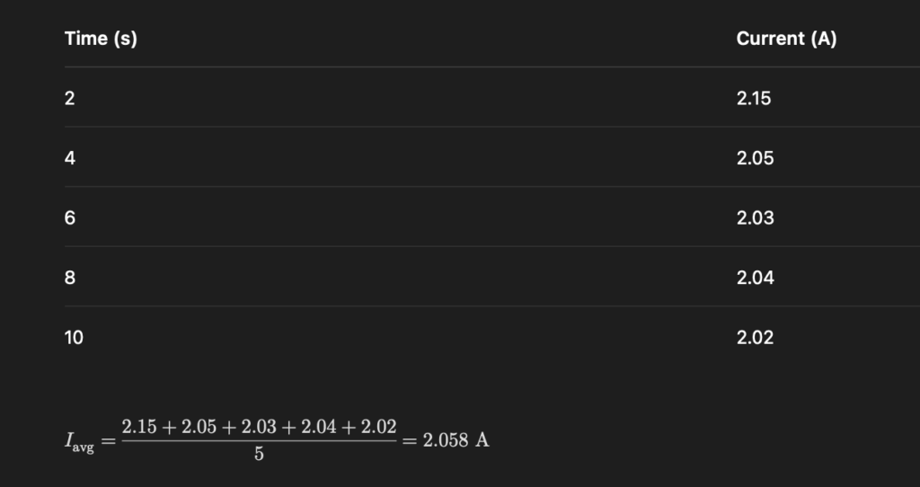
- During the test, the electrical current drawn by the rover’s motors was not constant.
- As the rover moved through the uneven terrains, the motors drew varying amounts of current at different times.
- To account for this variation, we measured current at 2-second intervals while the rover was in motion.
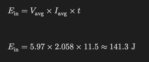
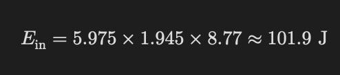
Energy Input:
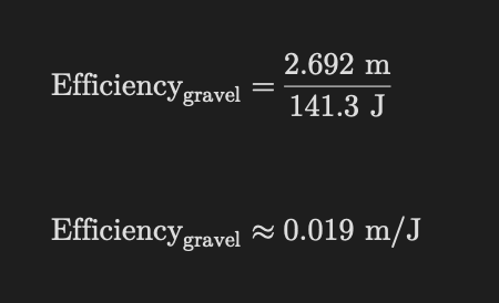
Efficiency Calculation:
- In this project, efficiency is defined as distance travelled per unit of energy input (m/J), rather than thermodynamic efficiency.
- This value describes how effectively the rover converts electrical energy into forward motion.

Test 2: Smooth Surface
- Temperature: 3 °C
- Distance travelled: 106 inches = 2.692 m
- Time: 8.77 seconds
- Mass of rover: 1184.2 g = 1.184 kg
Electrical Measurements:

Current Measurements:

Energy Input:
Efficiency Calculation:

Comparative Efficiency (Test 1 and 2):
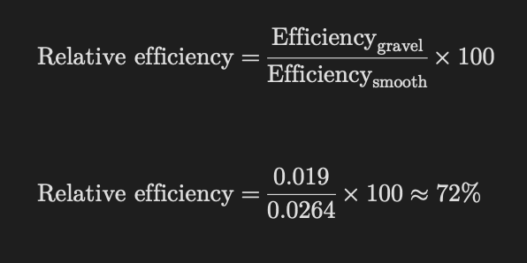
- This means that the rover operates at approximately 72% efficiency on gravel compared to a smooth surface.
- This decrease in efficiency is expected due to increased rolling resistance, wheel slip, and energy loss when traversing uneven terrain.
- Despite this reduction, the rover maintained stable motion and consistent traction, demonstrating that the rocker-bogie suspension system effectively supports traversal on rocky surfaces similar to those expected on TRAPPIST-1e.
Why we used this approach:
- By comparing the rover’s efficiency on gravel to its efficiency on a smooth surface, we isolated the effect of terrain roughness while keeping all other variables constant, including vehicle mass, motor configuration, battery type, and test distance.
- The smooth surface test acts as a baseline representing near-ideal operating conditions, while the gravel test simulates the rocky terrain expected on TRAPPIST-1e.
- This comparison enables us to evaluate how well the rocker-bogie suspension system maintains performance in realistic terrain.

Implication for Trappist 1-e
- The results of our tests provided insights into the vehicle’s performance on Trappist-1e.
- Our vehicle operates at approximately 72% efficiency on gravel compared to a smooth surface, which closely simulates the rocky terrain expected on TRAPPIST-1e.
- The decrease in vehicle efficiency on rocky surfaces suggests that rough terrain significantly increases energy consumption due to higher resistance, wheel slip, and energy losses during climbing.
- Despite reduced efficiency, our rover maintained stable motion and continuous traction during the gravel test, suggesting that the rocker-bogie system is well-suited to the conditions of Trappist-1e.
- Our tests showed the rover is about 72% as efficient on gravel as on smooth ground. If TRAPPIST-1e’s surface is closer to “gravel-like,” the real rover should assume it needs about:
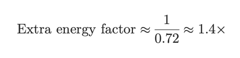
- So the real vehicle should be designed to deliver ~40% more energy than you’d estimate under ideal conditions.
- In terms of the battery:
- A sealed, dust-proof battery pack mounted low under the floor, offering stability and balance
- It should be thermally insulated and heated/cooled as needed, since battery performance degrades in cold conditions.
- In terms of charging and the use of nuclear energy:
- A small fission reactor at the base provides a constant power supply for charging.
- The rover runs on battery power for the 10 km round trip.
- This guarantees reliable energy even if sunlight is weak or conditions are harsh.
- In terms of materials
- We would prioritize strength, temperature durability, dust resistance, and radiation protection.
- We would use materials such as aluminum alloy for the frame and structure, and Titanium for the pivots and joints, to ensure strength and durability.
- We would use carbon fibre and Insulation layers that are lightweight and can withstand temperature changes.
- We would reduce the radiation by placing Polethylene – based shielfding on the vehicle
- Overall, these material choices balance the vehicle’s durability and safety with mass efficiency, increasing the vehicle’s weight slightly while ensuring efficiency on Trappist-1e
- Impact of the Vehicle Mass:
- The mass of the vehicle will affect the energy consumption of the vehicle.
- A heavier vehicle would need more energy to counter rsistance to climb obstacles
- Although the gravity of TRAPPIST-1e is similar to Earth’s, the vehicle mass still directly affects energy consumption.
- Rolling resistance and obstacle climbing forces are proportional to mass, meaning that a heavier rover would require more energy per kilometre even under similar gravitational conditions.
- Therefore, minimizing the mass will be critical for us to traverse on Trappist 1-e.
- The mass of the vehicle will affect the energy consumption of the vehicle.
Energy capacity for the real vehicle:
Relative Efficiency: 72% = 0.72
- This means gravel is approximately 72% as efficient as a smooth surface.

This means that:

To calculate the total energy needed for the 10km trip:

Assuming that the vehicle will be travelling at 1 kWh/km:
- This is the best-case scenario

Assuming the vehicle will travel at 3 kWh/km:
- This represents the worst-case scenario

Thus, without a safety margin, we get:

To account for potential malfunctions and unexpected performance degradation, we add a reserve/safety margin to ensure the rover reaches the destination safely.
- A common amount for the reserve is 30%-50%
Let the reserve factor be:

Battery capacity becomes:

Low end with reserve:

High-end with reserve:
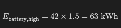
Thus, the justified capacity range is:

We find the midpoint of the range to average the lower and upper energy estimates:

Thus, the representative/nominal design value is:

- If we use the 18 kWh value, it would be the minimum value for the vehicle to function
- There is too much risk involved
- The vehicle may encounter detours or issues that prevent it from completing the trip.
- If we were to use the 63 kWh value, it would be very safe
- But the drawback is extra weight and the need for less energy to cover just 10km.
- Thus, the 40 kWh value balances:
- efficiency
- safety margin
- mass constraints
To select a realistic design value, we averaged the lower and upper energy estimates (18–63 kWh), resulting in a representative battery capacity of approximately 40 kWh for the full-scale vehicle.
Summary:
- We estimated full-scale battery capacity by assuming a plausible smooth-terrain energy use (1–3 kWh/km), applying our measured rough-terrain penalty (×1.4), then adding a 30–50% safety reserve, which gives an approximate mission-safe capacity of 30–60 kWh for a 10 km round trip.

Conclusion:
Based on our tests, the vehicle can traverse both smooth and rocky surfaces without issues such as stutters or incidents where it can’t push over rocks.
- Our vehicle did not encounter any issues regarding the direction it was travelling and maintained a good and steady pace throughout the test
This shows that the rocker bogie system improved the vehicle’s stability and its ability to climb rocky surfaces.

Possible Improvements:
After reviewing our vehicle’s performance in the tests, we could definitely see room for improvement.
- Improving Wheel Traction: A grippier wheel surface would reduce slipping on loose gravel and improve overall vehicle stability.
2. Distance between the wheels on the rocker arms and the bogie arms: We see that the distance between the wheels attached to the rocker arms and the bogie arms is not as far apart as we wanted.
- If we were to increase the gap between the wheels, the vehicle would be able to climb uneven surfaces more effectively, since it would be able to utilize the full benefits of the rocker bogie system
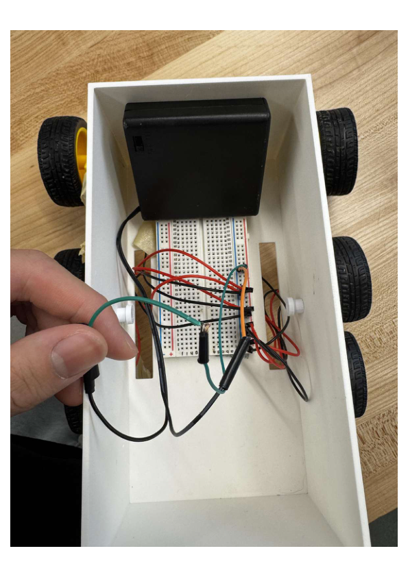
3. Better Weight Distribution:
- As shown in this image, the battery and breadboard don’t have a fixed slot to slide into and fit properly.
- This caused the vehicle’s contents (battery and motherboard) to shift within the vehicle on uneven terrain.
- Creating fixed slots would definitely help the vehicle achieve a more balanced state and better weight distribution.

Use of AI
- ChatGPT was used to plan and support the vehicle design, prototyping, and testing stages of this project.

Leave a Reply