March 12th, 2026
This blog post will outline an update for my personal project (which can be reviewed in the “first pitch” blog post). It will include my progress, timeline, and review the problem and solution.
Problem:
Definition Statement
Families of people struggling with addiction in South Asian, Middle Eastern, and other Eastern cultural communities are left completely without support due to cultural shame and stigma around mental health. Existing tools are built on Western, clinical frameworks that don’t account for these cultural realities. No tool currently exists that calms a family member physiologically, speaks their language, and understands their cultural context well enough to actually help them.
Pain Points
Target Audience:
The target audience for this problem, solution, and project is a very niche group of ethnic or cultural individuals who struggle with addiction or mental health, along with the corresponding families that care about them, but do not know how to help. These individuals can come in all ages or backgrounds, however an approximate age classification is individuals ranging from about 30 – 70 years of age. For the older members of this audience, there is great stigma (especially for men) surrounding help for mental health, which causes them struggles in the healthy management of emotions or addiction. Moreover, coming from cultural backgrounds, many of these individuals lack technological skills; when paired with cultural nuances in diction and norms, these individuals are often left feeling isolated and become difficult for families to support.
Research:
Over the past few weeks I have conducted thorough research into addiction psychology, the neurological sequences of the individual affected, and the impact on families. While I still have further research to complete, I have examined sections of two research papers along with a biography written by a neuroscientist.
Research Paper #1: The Science and Moral Psychology of Addiction: A Case Study In Integrative Philosophy Of Psychiatry
This research paper contained a substantial amount of information as to the actual thinking and processes that occur in the mind of an addicted individual. Amid this influx of information, I challenged myself to efficiently filter through it and find information that was specifically relevant to my project.
Hybrid Intentions:
Firstly, I learned about motivational states called hybrid intentions by the author. I learned that these are very closely related to action but are distinct from typical intentions in terms of being subject to free will. I initially was perplexed that the author calls these intentions “motivational liabilities” (129), because in a way, this contradicts his previous statement saying that hybrid states are related to action. However, after analyzing the context in which this was stated, I found that he means that hybrid intentions negatively motivate the “agent” (the individual) to conduct action and are more difficult to control. For my project, this learning about hybrid intentions prompts a deeper question which I will strive to answer in my next phase of research: How can hybrid intentions be mitigated and what causes them to have such an influence on the agent?
Assess the state of mind:
Secondly, I learned that instead of asking whether or not to blame the addict, it is more accurate to assess their character (their more or less stable set of cognitive, behavioural, and affective disposition. This is crucial for the way in which I construct the AI portion of my solution, as it means that I must program the AI to come across as comforting and not at all condescending, even if it is by AI error. This will pose an ethical concern over whether or not this AI can in fact use this research to comfort an individual, or whether it instead derails them further into their state of mind.
Here is the link to the paper: https://research.ebsco.com/c/m7jfwd/viewer/pdf/l3xn462isf
Research Paper #2: The Psychology of Addiction
This research contained comprehensive information as to the intrinsic motivators behind addiction, specifically drugs or alcohol. Once again, I was challenged to filter through to only the most relevant information for my project.
Humans need stimulation:
One of my crucial findings from this paper was that it is part of the primitive instinct for humans to crave stimulation. This craving for stimulation comes when we fall below the “comfortable equilibrium” (7), according to the paper. I found that this is a particularly dangerous zone, as this is where individuals begin to turn to harmful substances such as drugs or alcohol. After this finding, I found that it would be particularly interesting and effective for my project if I could find a way to trigger the same dopamine of stimulation from a calm and comforting AI device.
Drugs release dopamine:
While we hear about the dopamine that we are all addicted to in the form of social media, this same dopamine is released from drugs. This is the dopamine that cures our craving for stimulation and fuels the heart of addiction for addicted individuals. As I came across this section in the paper, I found myself asking the question: What if there was a way to cure a state of vulnerability and longing for dopamine, by triggering a small amount of a positive kind of dopamine? This is a question that I will continue to explore in my continued research, and if I can find a way to integrate it into the AI’s framework, I believe that it will have a positive effect for individuals.
Biography: Memoirs of an Addicted Brain
This is a biography by Marc Lewis, which outlines his addiction, starting with childhood experiences and moving through a 15-year struggle with drugs, including heroin, LSD, and meth. It describes a life of desperation, crime, and, ultimately, recovery. This is especially useful for my project as it clearly provides the addiction process, which is something that I will be learning from throughout my project. In terms of specific concepts, I have not yet comprehensively read the novel yet. More details about specific psychological concepts will come in a later blog post.
This is a physical source, therefore no link can be provided.
Solution:
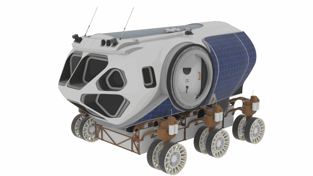
Prototype
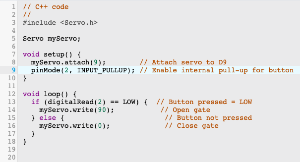
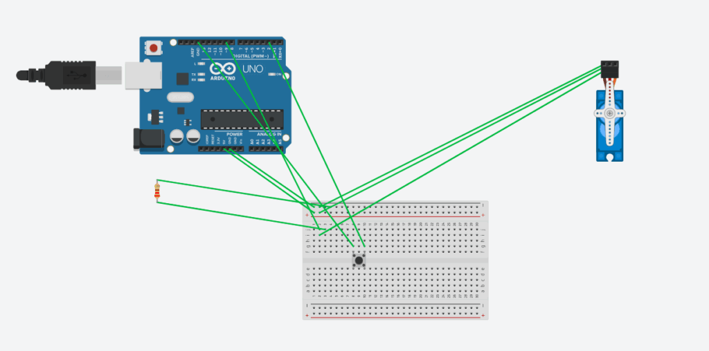
This solution will be a physical device that includes a button. In times of need or emotional vulnerability, it is easily accessible for the struggling individual to press. Once it is pressed, an AI audio begins to play that speaks to the person in a calming and comforting manner in their language and understanding their cultural nuances. The person has a conversation with this automated assistant until they feel comfortable and stable, from which point they can ask the audio for a recommendation or seek help of their choice. This prototype would go beyond addiction to create safe space for mental health in communities that have never had one.
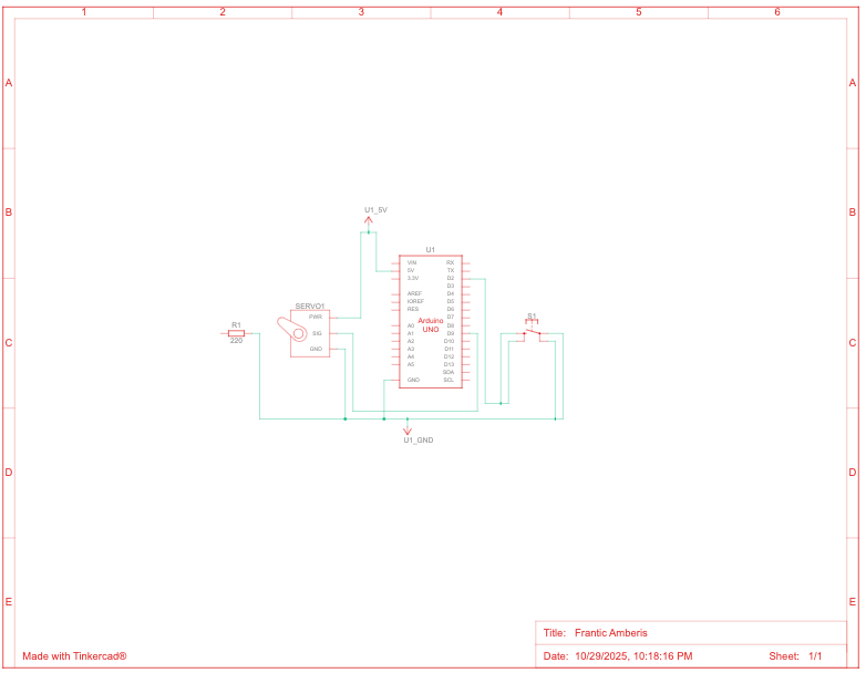
Building
Throughout the building process, It will include several intricate components:
Physical Components
- Haptic feedback motors for calming vibrations
- LED lighting system for breathing guidance
- Built-in speaker and microphone for voice AI interaction
- Discreet design to look like an ordinary object, not a medical device
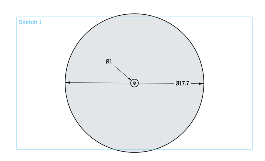
- 3D printed housing with handcrafted elements
AI Components
- Understands cultural norms around emotional expression and family honor
- Built using Claude
- Multilingual capability: Punjabi, Urdu, Hindi, Arabic, Mandarin, and more
- Trained on CRAFT methodology and culturally specific communication strategies
- Voice-only interface. No text or screen
Testing
In terms of testing, it will involve a testing plan that includes the following:
- Present prototype to addiction counselors for clinical validation
- Present to members of South Asian and other cultural communities for cultural accuracy
- Test whether biofeedback component effectively reduces stress
- Validate whether AI responses are culturally appropriate and helpful
- Cannot test on actual families in crisis due to ethical boundaries
These phases correctly test the prototype against the definition statement, as they account for cultural nuances and testing against real addiction centred areas.
Progress:
Notion Board
The first step to this project for me was to create an organized notion board which allows me to track my progress and outline clear tasks within a measurable timeline. In this board, I created several unique phases including: research, learning, design, building, AI development, integration and testing, refinement and documentation, and presentation.
Research
As previously mentioned, I focused the past few weeks on cementing my understanding of addiction psychology. This involved reviewing several unique sources such as the research papers previously mentioned along with the novel. I still have much to learn about cultural nuances and CRAFT methodology, which is what I will continue to cement into my learning.
Challenges:
Learning
The major challenge for this project will be the learning phase. My understanding of skills such as coding, Arduino, AI development, and others is highly limited, which is why truly learning these skills for my ambitious project will be challenging.
Adherence to Timeline
Ensuring that I follow my timeline and do not fall behind is crucial, as this project involves several phases and steps to ensure it is completed to make the most impact possible.
Aside from these challenges, I believe that I will find great success in following my outlined project plan in Notion.
Next Steps:
The next steps for my project for the near future are to finish my research and to begin and complete the learning phase.
Finish Research Phase
While I have already completed significant research into addiction psychology and intrinsic motivation, I still have research to execute. My understanding of cultural nuances, CRAFT methodology, and other psychological concepts is still not where I would like it to be. This learning for me, is extremely significant and interesting for this project, and solidifying a comprehensive understanding will serve me well in the later phases.
Learning Phase
This phase will be crucial for my project, as it will equip me with all of the skills necessary to build both my physical prototype and the AI model. Specifically, I will be learning skills such as 3D printing, Arduino, Claude AI development, coding, and several others. I believe that using AI to learn these skills will be significantly efficient and helpful.
AI Usage:
So far, I have used AI to understand complex parts of research papers and psychological concepts that I do not understand.
Here is the full transcript: