October 4th, 2025
This project was intended to demonstrate a basic understanding of CAD skills in Onshape. These skills included:
- Sketching – drawing a 2 dimensional representation of a face in CAD
- Extruding – taking a sketch and turning it into a 3 dimensional object
- Assembly – taking multiple 3 dimensional parts and sticking them together
- Mechanical Drawings – converting your 3 dimensional parts and/or assembly into a 2 dimensional drawing
- BOM – Bill of Materials – creating a list of all items required to fabricate an assembled object
As someone who was completely unfamiliar with CAD and Onshape, I used a specific Notebook LM AI to guide me through the process and teach me these skills.
Here is the transcript for all of my interactions with AI:
Technology Explorations 10 – CAD Assignment AI Transcript – Hukam Singh Kang
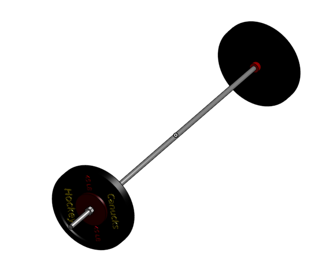
As for the project itself, I decided to create a basic barbell with 45 pound weights attached to it. It includes various simple elements that when put together, allowed me to learn the basics of CAD. In this blog post, I will show the sketching and extruding phases for only the plate, as the other parts followed a similar process.
1. Plate Design
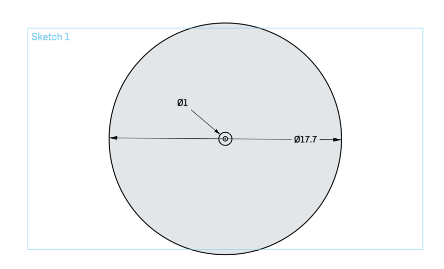
Step 1: Sketching
The first part of this project was the sketching of the plate. This sketch represents the base of the plate, before I added extra details. The diameter is 17.7 inches (standard), and there is also a smaller circle in the middle (1 inch diameter). Two circles are needed because later on during the extruding phase, I only wanted to extrude the area around the small circle, leaving a hole in the middle.
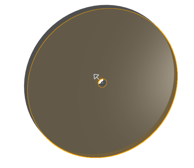
Step 2: Extrusion
The second step in designing this plate was extrusion. This process involved selecting the part that I wanted to be turned 3 dimensional, and making it happen. I selected the larger circle and this is a preview of what it would look like once extruded. I chose the depth of the extrusion to be 2 inches, as this is the standard thickness of weight plates.
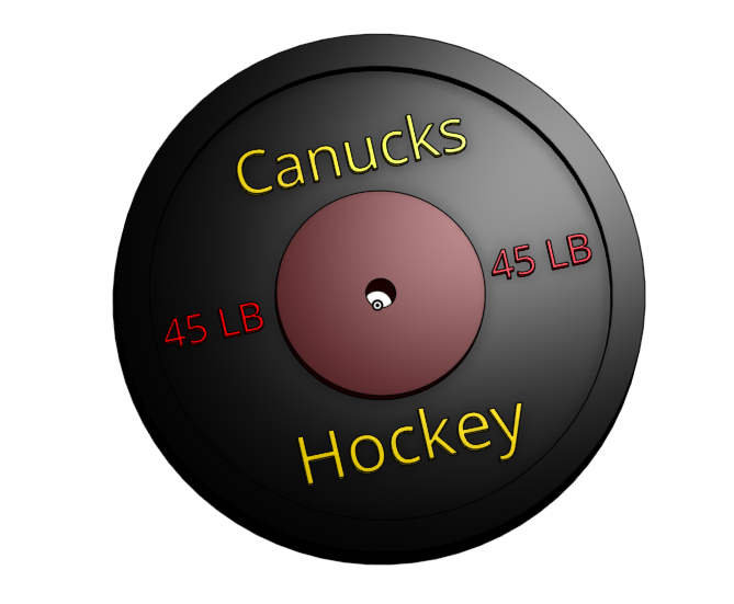
Completed Plate:
The previous two steps were simply to demonstrate my understanding of sketching and extrusion. However, I repeated this process multiple times to reach my completed weight plate.
For example, the outer ring required a sketch and extrusion of a 17.7 inch diameter circle, with a much larger inner circle (to create a thin outer ring). The dark red innermost circle also required a sketch and extrusion following a similar procedure. These three circles allowed me to practice and get comfortable with this skill, so that I found it easier to demonstrate in other parts of the project.
By layering each circle on top of each other, I learned that when drawing, you can select an already extruded part as the plane. An interesting feature that I learned in my pursuit to add detail to a once simple plate was the ability to add text. Notebook LM aided me in this process, and youtube videos were especially useful in visualizing it. Finally, I learned how to choose the colour of each part (again through Notebook LM), which made the final design look especially polished.
2. Barbell Design
Step 1: Sketching
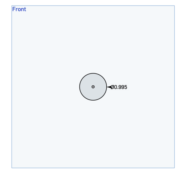
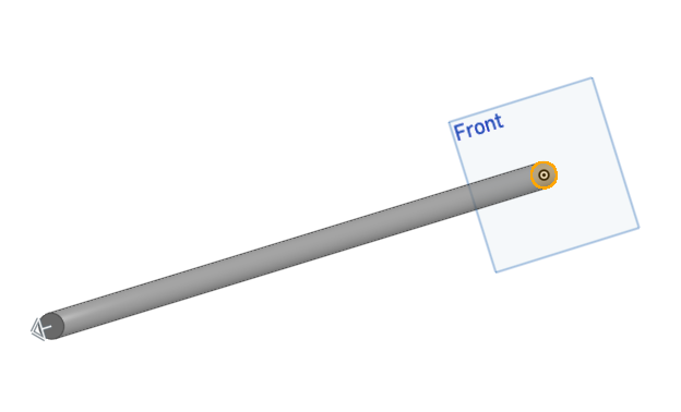
The first step in creating the barbell was sketching the bar itself. This included using the centre circle tool to draw a circle centred to the origin. The diameter had to be slightly smaller than the hole in the middle of the plates to allow them to slide on.
Step 2: Extrusion
The second phase in creating the bar was extruding the sketch. This process was quite straightforward, as it was a solid bar without anything in the middle. The depth of the extrusion had to be 64 inches due to the extra parts that would allow it to be functional.
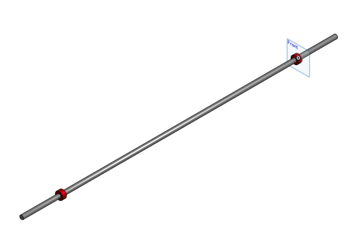
Completed Barbell:
The final barbell was created by adding more parts to the initial bar shown previously. Of course, the bar needed stoppers to prevent the weight plates from colliding. In order to include them, I was required to do mathematical calculations regarding the length of the overall barbell.
This involved creating 2 separate 8 inch bars which I added to the original bar and stoppers using the extrude tool. Through this process, I learned that two separate extruded parts could be merged, which helped me with the previous part as well. The completed barbell set the stage for the creation of the final part – the outside stoppers.
3. Outside Plate Stoppers:
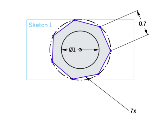
Step 1: Sketching
The first step in the creation of the outside stoppers was again sketching. For this phase, I used a heptagon to best represent the strapped stoppers that are usually used in gyms. Each side is 0.7 inches, and the inner circle had to have a diameter of 1 inch to allow the barbell to fit through. Again, the sketching was simple, getting ready for the extrusion phase.
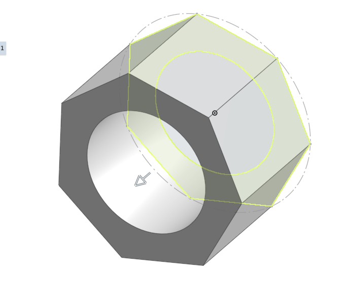
Step 2: Extrusion
The extrusion phase was similar to the process used for the plates. I had to select the part outside of the inner circle to leave the hole. Other than this, it was again, a simple process. This part was the simplest as it was 1 part, without any additions.
4. Assembly:
Completed Assembly:
The assembly part of this process was difficult to understand at first. Elements like mates, and finding a way to add restrictions on them was challenging at first. During this process, I set the barbell as the fixed element, making it easier to slide the rest of the elements on it. I used cylindrical mates to connect the plates and the bars. I learned that these allow the user to spin/rotate them and slide them along the plate.
During this phase, I learned about setting restrictions on the distance that they could slide. Of course these were necessary, as I did not want them to slide past the built in stoppers. I set the restriction to 8 inches for the plates because this was the distance to the stoppers. After completing these cylindrical mates, I created slider mates for the sliders because realistically they should not be able to rotate. I set the restrictions to 7 inches for these mates.
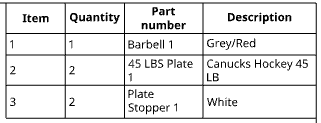
After this, the assembly process was complete, but it took me some time to understand that the Bill of Materials had to be created in this assembly tab. Notebook LM helped me with this, so I was able to create the table listing the various parts used for the project.
5. Mechanical Drawings
Completed Drawings:
During this final phase of the project, I learned that various angles of the assembled product could show different sets of dimensions. For example, the horizontal view showed the length dimensions of each element, while the vertical view showed the width dimensions. I included the front of the product, to show circular elements in greater detail. As a whole, this was a straightforward process, however, it took me some time to understand it.
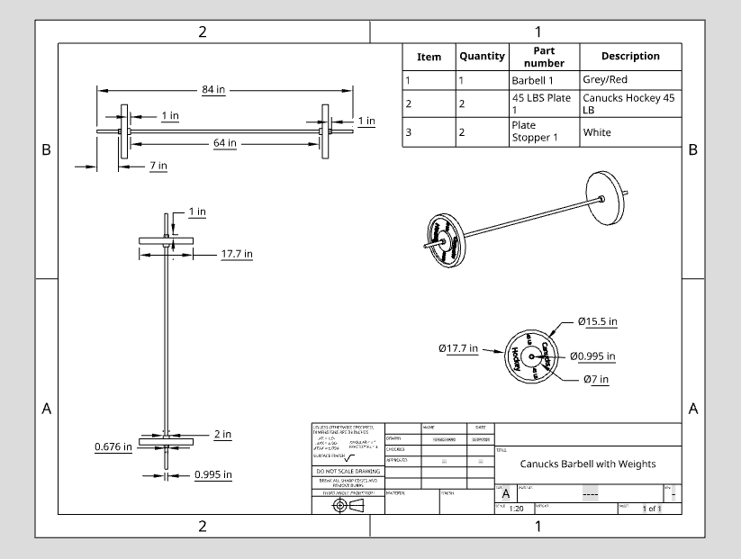
6. Bill of Materials (BOM)
Completed BOM:
Finally, the Bill of Materials needed to be inserted into the mechanical drawing document. Again, this was straightforward, as I had already created it during the assembly phase.
Ultimately, this project was the right project for me, as it taught me basic CAD skills that I am now comfortable with. Through working with a product that interested me, my craving for knowledge led me to learn more than I would have, had it been a product that I had no interest in.
To view the whole project in CAD click on the following link:
This was a great first project, and stay updated for many more to come!
Leave a Reply