For this assignment, I took the learning-focused path instead of creating a full model from scratch. I wanted to understand the core workflow of CAD (how sketches, extrusions, assemblies, and drawings all connect) before I tried to make something ambitious. I followed the Onshape learning pathway and built a series of small, symbolic parts that relate to the structure of a transformer model. It became a way to understand both design principles and the way complex systems are built from simple, well-defined pieces.
Sketching and Constraints
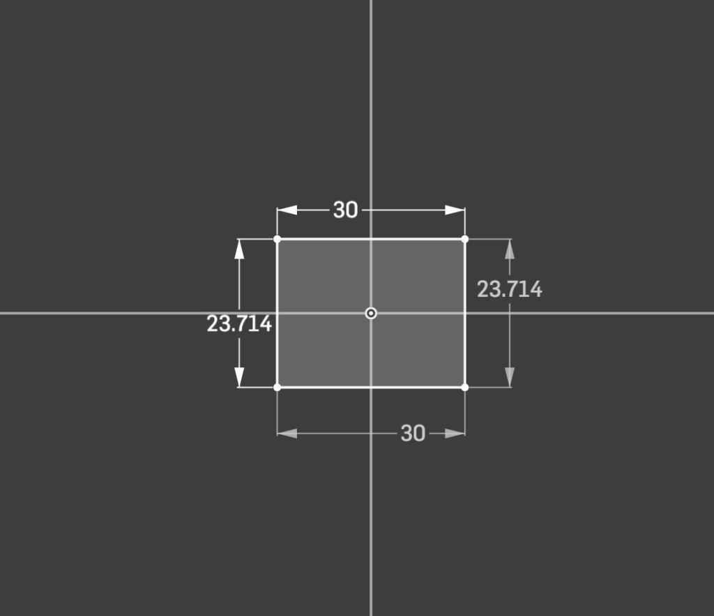
The first part I made was a simple 30×30 mm square. It represented a single token, the smallest building block in a transformer. I drew the square from the origin, added equal and horizontal/vertical constraints, and made sure the lines turned black, meaning fully defined. This was my introduction to precision: the sketch only behaves predictably when every relationship is constrained.
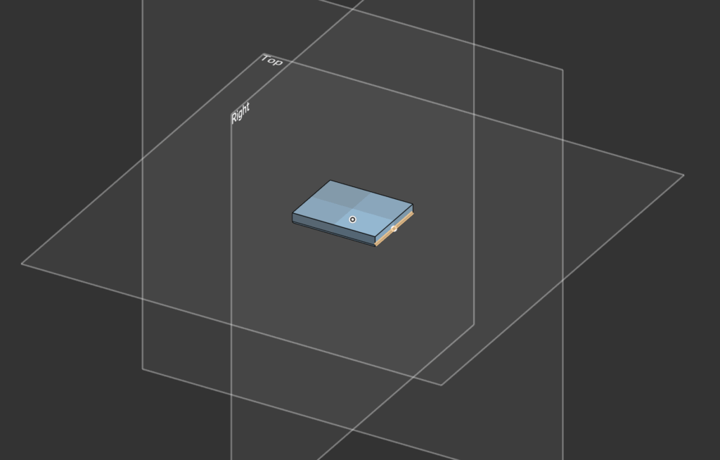
After finishing the sketch, I extruded the square by 4 mm and added a 1 mm fillet on the edges. That small step turned a flat, two-dimensional idea into something tangible. It felt like an “embedding,” a basic analogy for how data gets transformed from a sequence of numbers into something with depth and geometry.
Modeling the Attention Dial
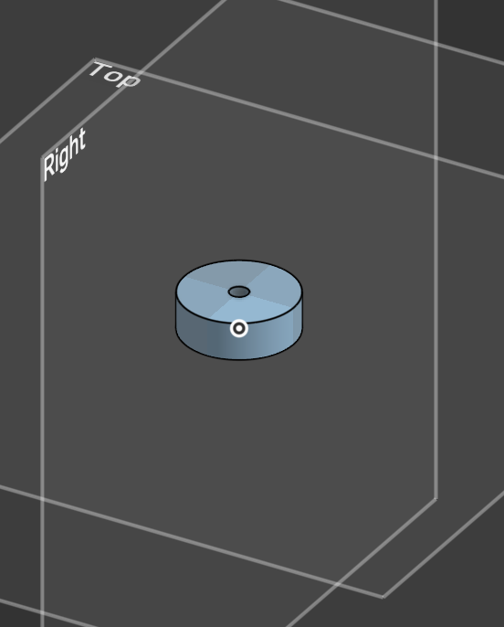
Next, I learned to revolve and extrude circular shapes. I created a simple dial:
A 24 mm diameter cylinder, 8 mm thick, with a 4 mm hole through its center. This part symbolized an attention head. The hole became the pivot point for rotation, which I’d later use in the assembly to experiment with motion.
The process introduced me to more complex geometry, including concentric constraints and the use of reference dimensions to keep everything parametric. This part also made me appreciate how small design decisions (like leaving the center hole) make the assembly process smoother later on.
Assembly and Mate
Once I had a few small parts, I opened a new Assembly workspace. I added a flat base plate, fastened it to the world, and attached the dial using a revolute mate. That simple mate allowed the dial to spin freely while staying aligned with its axis.
Seeing the dial rotate felt like the moment the whole process clicked. The revolute mate represents controlled movement; one degree of freedom. It perfectly mirrors the idea of an attention mechanism adjusting its focus. The difference between a fastened mate (no movement) and a revolute mate (single rotation) also helped me understand how constraints define motion in CAD.
Drawings and the Bill of Materials
Following the feedback to include my mechanical drawings, I realized I could go one step further. Since a Transformer model is just math, and CAD is just geometry defined by math, I built a “Digital Twin” of my assembly to test the mechanical logic before “manufacturing.”
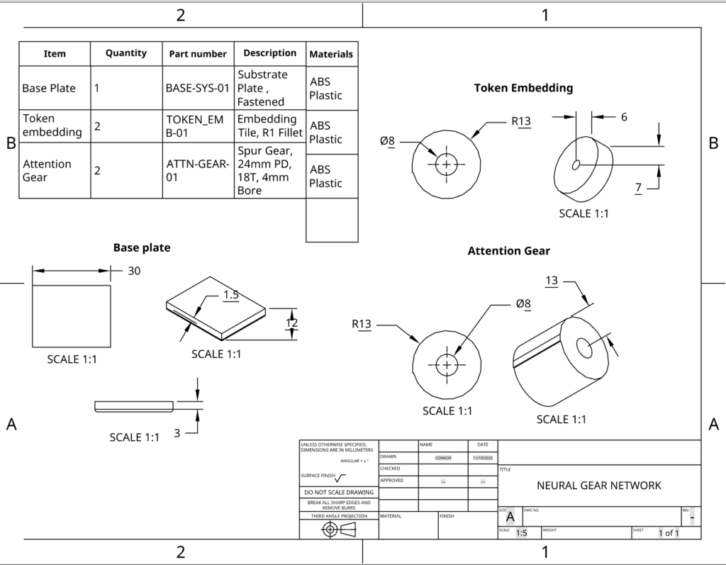
First off, the Hardware Dependencies (BOM).I cleaned up the dimensions to ensure standard sizing for the input tokens and defined the specific gear ratio in the Bill of Materials (BOM).
This is where I wanted to push the project further. In software engineering, it’s know that you never ship code without running tests to verify the logic. I realized that since CAD is parametric (defined by math and relationships), I could “unit test” my mechanical assembly using code.
Demo
I built a digital replica of the assembly using React. I instantiated the specific rows from my Bill of Materials into the JavaScript runtime to verify the system’s behavior.
- The grey container represents the Base Plate (
BASE-SYS-01). Just like in the CAD assembly, this is the fixed substrate that holds the system static. - The blue dial corresponds to the Token Embedding (
TOKEN_EMB-01). In Onshape, this part has a rotational degree of freedom. In the demo, it is mapped to the user input state. - The red gears are the Attention Mechanism (
ATTN-GEAR-01). I programmed them with the exact physical constraints from the drawing: an 18-tooth design and a 1:1 gear ratio relative to the input.
This is where I wanted to push the project further. I wanted to explain how a piece of plastic could actually select words and formulate sentences. So, I built this demo:
How the Demo Works
In the dashboard above, I gave the model a “sentence” of 5 words. I divided the 360 degree circle of the gear into 5 equal “zones” (like slices of a pizza).
- Zone 1 (0-72 degrees): “THE”
- Zone 2 (72-144 degrees): “ROBOT”
- Zone 3 (144-216 degrees): “LEARNS”… and so on.
As you rotate the Blue Input Token, it physically drives the Red Attention Gear. The gear acts as a pointer. Whatever “zone” the gear lands in, that data gets activated.
The “Radio Dial” Analogy
Think of the Attention Gear (Item 3) like the tuner on an old radio.
- The radio has access to every station at once, but it only plays one at a time.
- To pick a station, you turn the dial.
- When the dial points to 98.5, you hear jazz. When it points to 101.1, you hear rock.
The Conclusion
This proves that the movement isn’t random. By rotating the gear to a specific angle, we are physically addressing a specific piece of memory. Just like a combination lock needs to be in the right position to open, the gear needs to be in the right position to “think” the right word.
Lessons Learned
Working through the tutorials taught me that sketches are the foundation of everything. Getting them fully defined is the difference between a stable model and one that behaves unpredictably. Extrusions are just geometry built on those rules. Assemblies are where motion and interaction come in, and drawings are how you prove your design works for someone else.
Each part (tile, dial, and base) taught me something about constraints, motion, or communication. Together they formed a small but complete system. And by using transformer concepts as metaphors, I could think about each step not just mechanically but conceptually:
- Tokens become tiles.
- Embeddings become extrusions.
- Attention becomes rotation.
- Feed-forward layers become fixed stages.
- Residual paths become links between parts.
Next Steps
If I revisit this later, I’d add a slider to represent shifting focus or connect two dials with a thin linkage arm to show a residual path. For now, this small collection of parts is enough to show that I understand the tools and the workflow, and that I can connect the logic of CAD to the structure of machine learning.
References
Here is a link to my demo: https://codesandbox.io/p/sandbox/trusting-buck-k8vr59
Here is my final CAD design (cannot share past St. George’s school): https://sgs.onshape.com/documents/4cef7508a5ce180e9427bc43/w/5aafeed653c6c9899b8833dd/e/c7e96911e28cc8f9f39a18f7
Leave a Reply