Hi, my name is Aiden and this is my CAD Assignment for my Fusion 10 program.
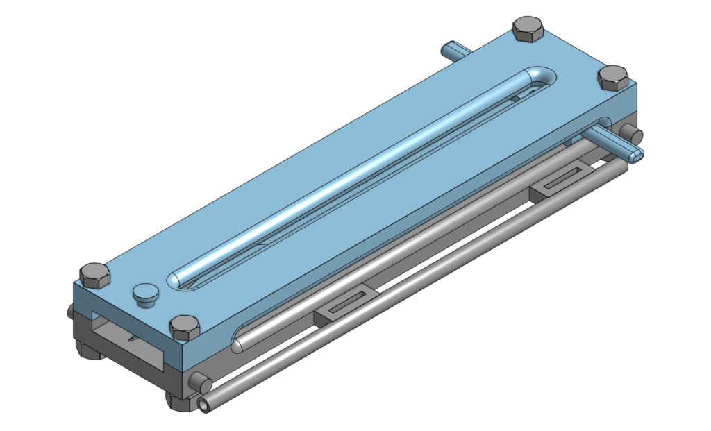
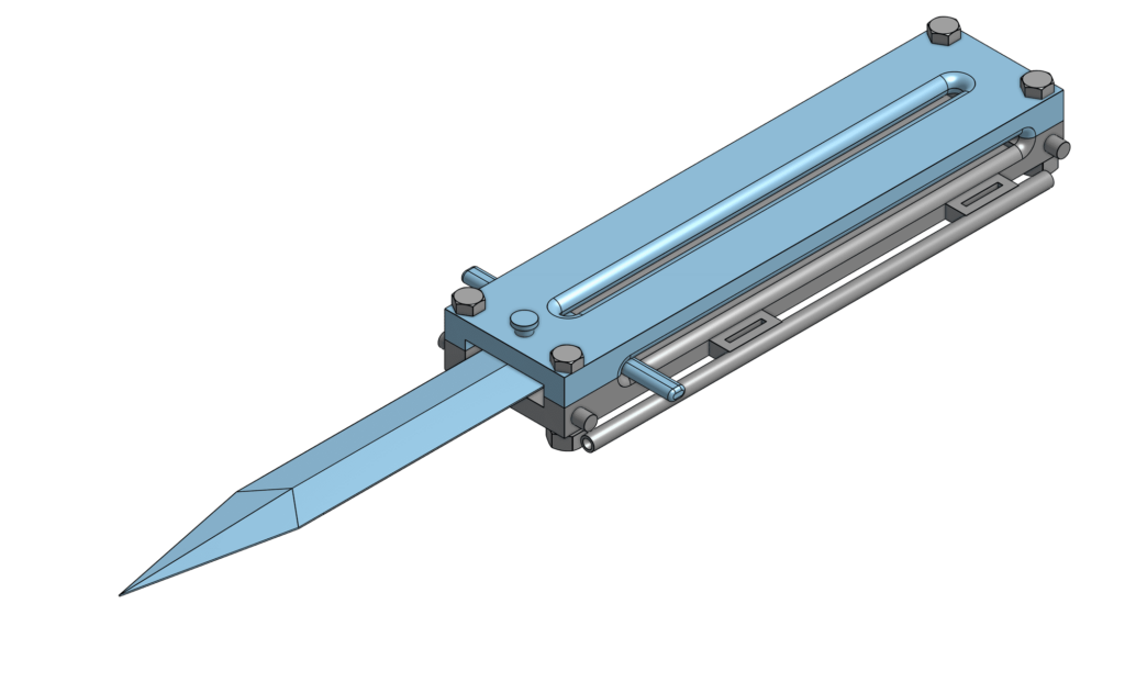
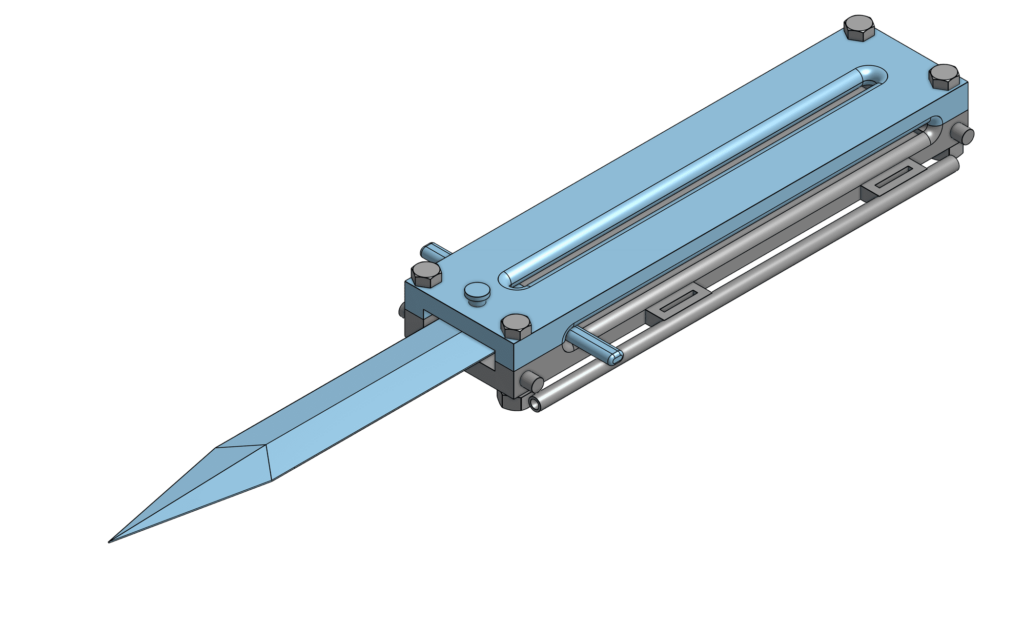
“Um, what in the smorgasbord is this,” you may be asking. Well, this is an Assassin’s Creed Hidden Blade (inspiration by JLaservideo, this guy built a functioning Iron Man suit), but it’s not really hidden as it’s supposed to be on the outside part of the forearm. Right now, the project is around 80% complete as I still need to insert a couple parts and a spring, but it’s basically done.
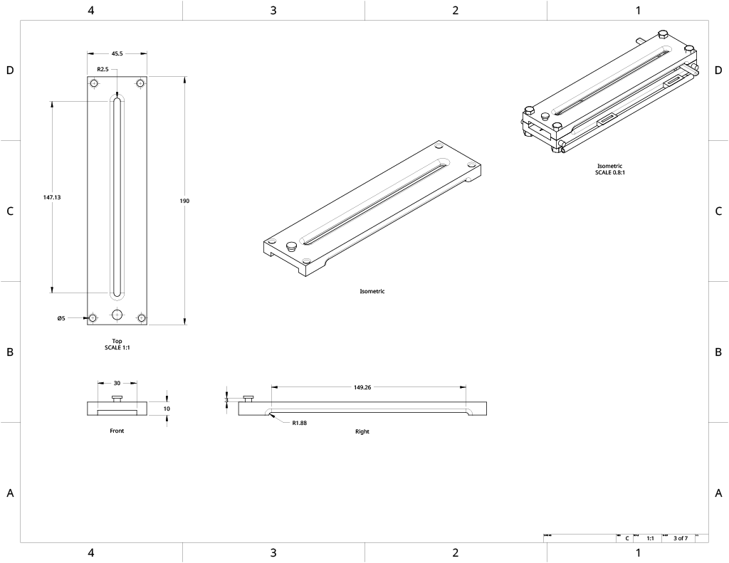
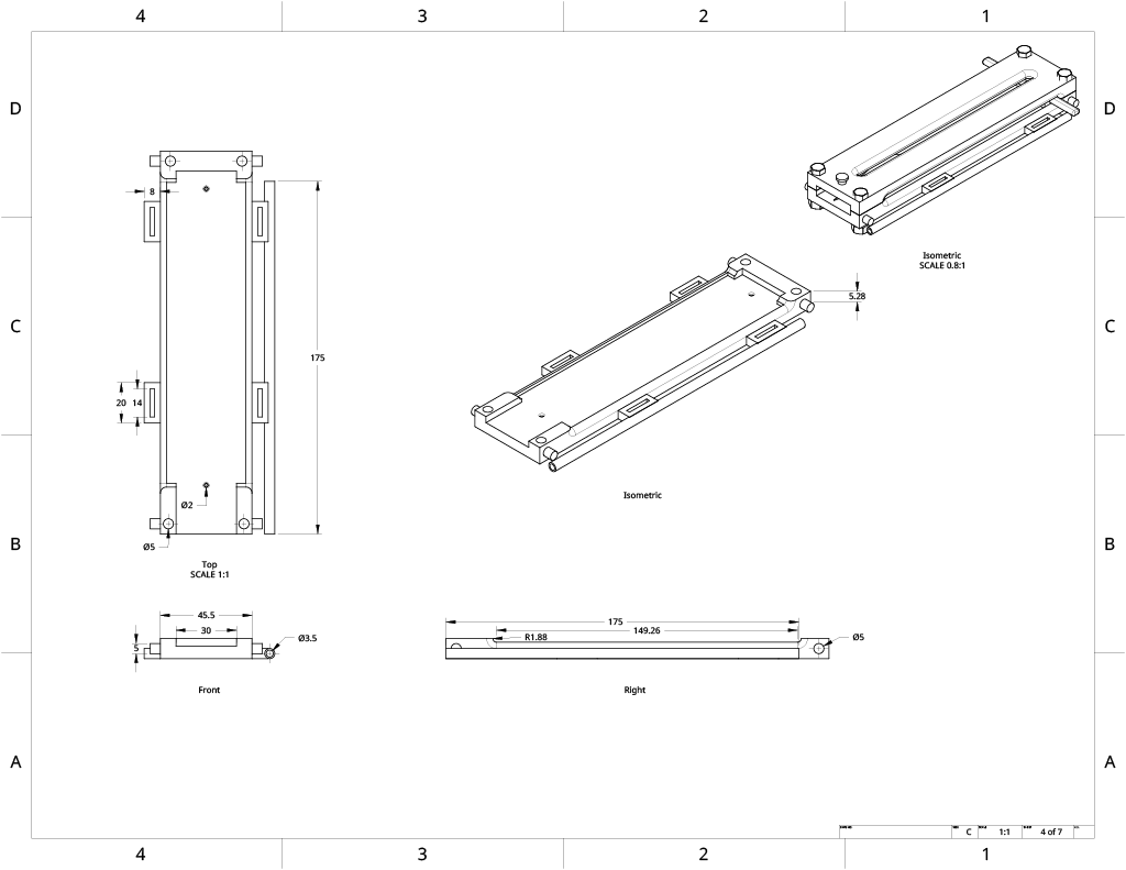
The entire thing is split into 3 parts: the top of the housing unit, the bottom of the housing unit, and the blade unit, as well as four pairs of nuts and bolts.
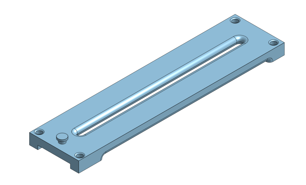
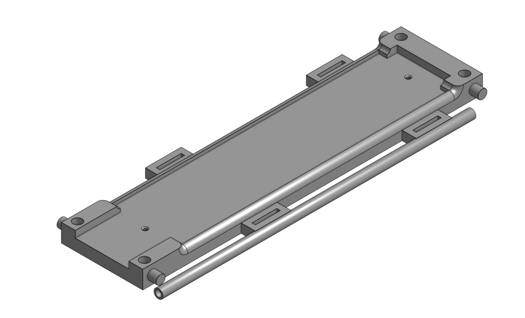
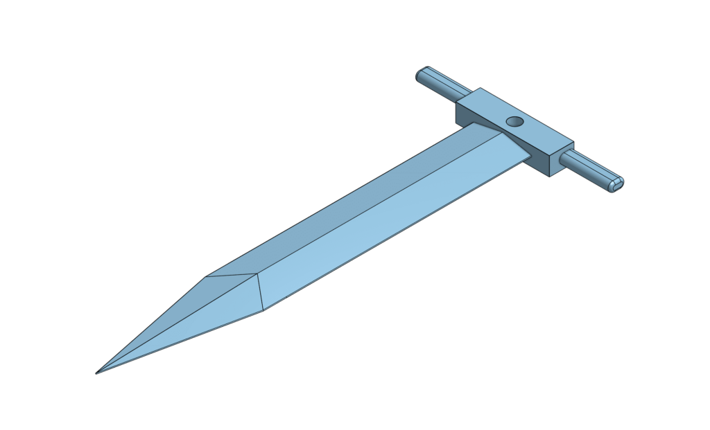
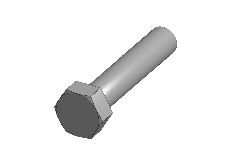
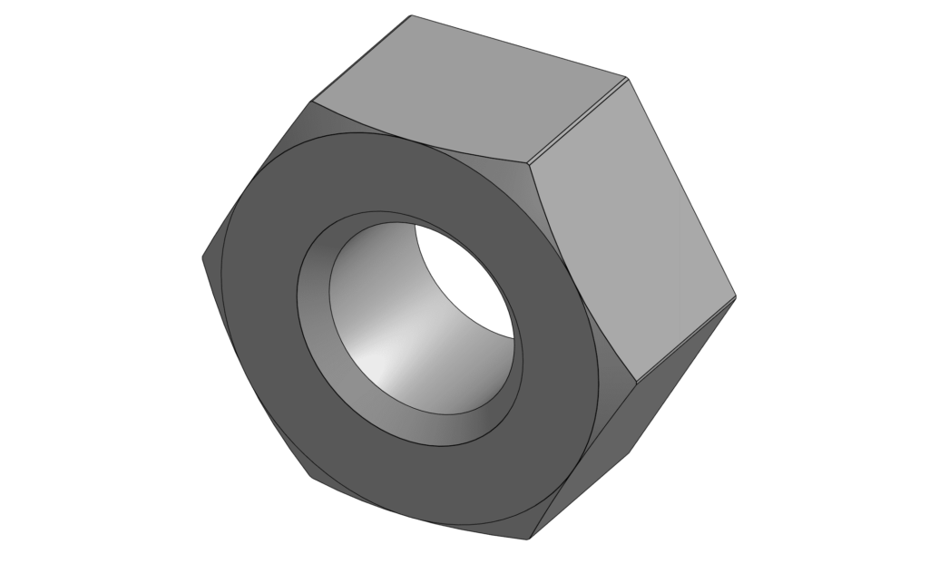
The housing unit has 3 rails in total. The 2 on the sides fit the charging handles and the 1 on the top fits a bolt that attaches to the blade unit. There are 4 holes to fit the screws, and 2 smaller holes on the bottom to lock the blade in place when it is extended or retracted.
The top part has a pin which is used to hold the spring in place. The bottom part has four extrusions that will fit Velcro straps as handles, as well as a tube to guide the string that will activate the blade for punishing evildoers.
I had made 3 versions of this project (wow!), improving certain parts of it as I went on. The first was practically just a proof of concept, as I was only concerned about the general shape and size of the item. It was completely unusable and it would fall out the front if I had printed it. (boo!) The blade part was so complex it took years off my life. (bummer!)
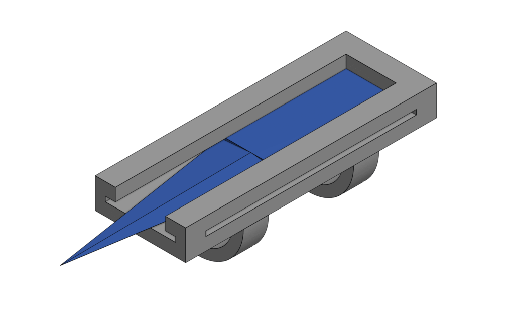
The second version was slightly better with a much more realistic blade design and a slimmer shape overall. It retained the arm cuffs and the problem of it falling out the front. I was going to further edit this one, but it was too big for my printer, so I decided to start over. (bummer!) I had gotten much better by this time than when I first started the project, since it was only my second time doing CAD in Onshape. (yay!)
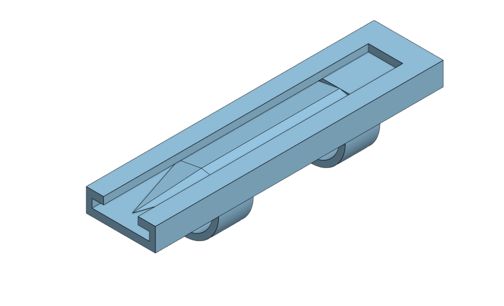
The third version is my current, although this would technically be considered the sixth or seventh. (wow!) I first started by resizing the whole thing, making it fit into the printer. Then I readded the side slots (which had been removed from the second version) and also added a top slot for the bolt that was going to go through the new blade (which I also changed to its’ current shape after more life-taking work). I had also changed the cuffs to slots in order to have a more flexible fit as a solid cuff would have a set size. I then put a hole in each corner to fit the screws as well as 2 holes on the bottom to fit a locking pin through. After, I added handles to the blade unit as to prevent it from falling out the front.

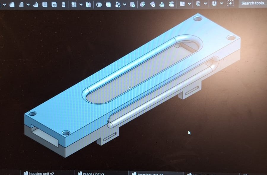
A previous iteration of this version, with larger slots and a wider design.

Blade Unit V3 in progress
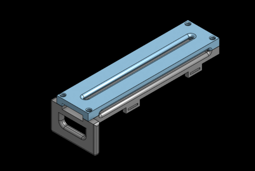
Testing a handle design, scrapped
However, after assembling it, I realized the top slot was too big and didn’t leave enough space for the blade to come all the way out. I decided to slim down the slot and make it longer towards the front. I also thinned the side slots to match the handle’s circumference.
I assembled it again and began thinking of functionality. I added a parallel mate to the assembly to see how the blade would move in the housing unit. I made more fixes to the slots to align the pin hole, the blade hole and the handles. I also shortened the blade as it didn’t fit completely into the housing unit.
I added pins on the corners to fit levers that would control the activation of the blade. Realizing the handle slots were still too small, I decided to position them perpendicularly to the bottom part and also attached a tube on the side for the string.
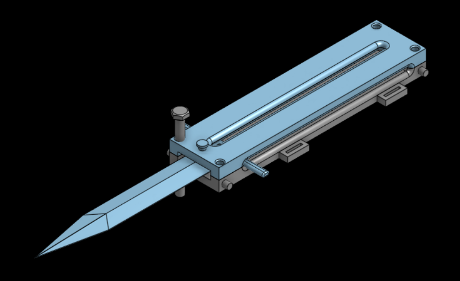
Testing different screws in the assembly.
After the main parts were done, I decided to begin importing nuts and bolts from different libraries offered by Onshape. (FYI, they are really big and I wasted a ton of time) I went through multiple libraries and found some that fit the holes I made.
I made some final edits (resizing the entire thing because surprise, the blade part didn’t actually fit, lining up the rails and pin holes for the 5th time) and it was done. (yay!)
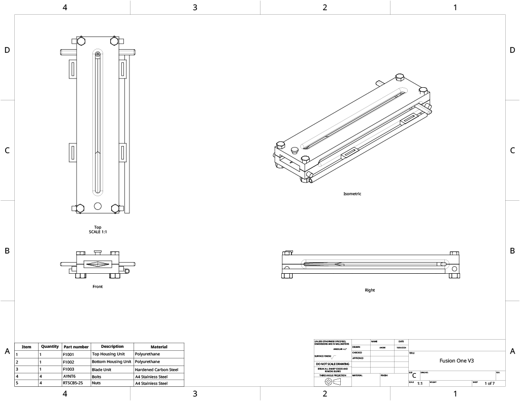
This project was quite complex and I had to learn a bunch of new things I had never done before. For this assignment, we had to demonstrate 5 points of learning: Sketching, Extruding, Assembly, Mechanical Drawings, and BOMs.
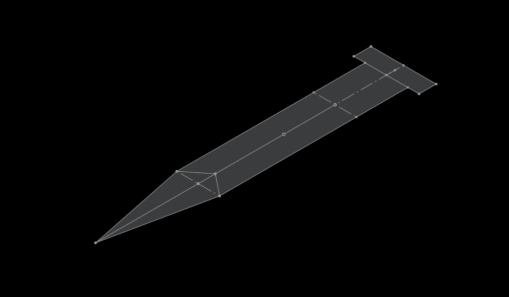
Sketching was easy for me. Being literally the most basic function of Onshape, I didn’t run into any big problems, although I learned to use construction lines better as well as sketching on existing parts of an extrusion.
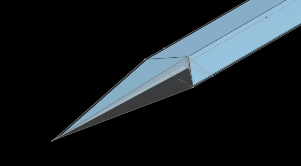

Extruding was simple at first. Every 3D object in Onshape has to be extruded in some way, after all. I learned to use New, Add and Remove in the Extruding tool. Later in the project, I also learnt to use some more advanced extrusion tools, such as Loft for the blade point. Figuring those out took me literal days.
It was my first time using Assembly in Onshape, and I wasn’t sure how to use it at first. I looked through the tools and learned to use mates such as Fastened, Slider and Parallel. I also learned to animate movement. The only thing problem was the toll it took on my potato of a computer.
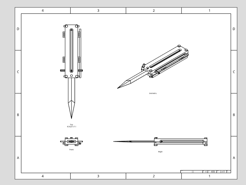

It was also my first time using Mechanical Drawings and BOMs. It was actually fairly simple to use (far easier than figuring out how to extrude along an angle for the blade). I made multiple pages for the different parts and angles. The BOM was even simpler. I just filled in the information and it was done.
I had to overcome many challenges in the process of this project. From slight errors in length that I had to basically redesign everything to fix to complex shapes that required a lot of thinking, this project is the culmination of a long series of trial and error.
Now, I’m going to get some sleep and let my laptop be before it explodes from loading the assembly.
Aiden
3 Responses to “Reasons I made a 3D-printed and Spring-Loaded Knife (Model) in my CAD Class – Intro Post 1”
You have done an outstanding job with this project, Aiden. You have clearly pushed through some tough problems and learned a lot in the process. The only place where I see a significant issue with your submission is that there are no dimensions in your mechanical drawing. Can you please add sufficient dimensions that someone else could take your drawing and fabricate it? Please resubmit when you’ve done this.
drawings 1 and 2 (assembly) have no drawings. only the part drawings have dimensions.
OK, Aiden. I see what you’ve done now. I’ll mark as complete.